ETC ALCR-DIN User manual

ETC Installation Guide
Automatic Load Control Relay
Corporate Headquarters nMiddleton, WI, USA |+1 608 831 4116
Global Offices nLondon, UK |Rome, IT |Holzkirchen, DE |Paris, FR |Hong Kong
Dubai, UAE |Singapore |New York, NY |Orlando, FL |Los Angeles, CA |Austin, TX
Web etcconnect.com |Support support.etcconnect.com
Contact etcconnect.com/contactETC |© 2023 Electronic Theatre Controls, Inc.
Trademark and patent info: etcconnect.com/ip |Product information and specifications
subject to change. ETCintends this document to be provided in its entirety.
7180M2151 Rev A Released 2023-02
Overview
The Automatic Load Control Relay (ALCR-DIN) is a UL924 listed device,
powered by a normal/emergency source. The ALCR-DIN tracks the state
of normal power and automatically bypasses control of
the load to the emergency state upon loss of the normal
power sense feed source or when triggered by an
emergency contact closure (for example, a fire alarm). The
ALCR-DIN ensures a lights-on state during loss of normal
power while tracking and matching the control state of
normal lighting loads during normal operation.
The ALCR-DIN provides a relay output that follows the
state of a normal input. Because the output is a relay, the
output side of the ALCR-DIN does not dim, however the
ALCR-DIN can be used in a dimming application when installed correctly
to do so. See
Examples of Use on page9
for details. Alternatively, the
ALCR-DIN can be secondarily connected to a 0-10 VDC control source.
Even with external 0-10 VDC control present, in an emergency state the
ALCR-DIN bypasses the external control source and allows the fixture to
switch to its data-loss state (On full).
Specifications
• Rated for indoor use only. 0°C–50°C (32°F–122°F), 10-95%
non-condensing humidity
• UL, cUL listed Emergency Lighting Equipment under UL924 at line
voltages of 120/277VAC, 60Hz.
• Load ratings:
‐Ballast load rating: 20 A maximum at 120 or 277VAC.
‐Incandescent load rating: 10 A maximum at 120 or 277VAC.
• For installation with field-installed conductors of 60°C minimum
rating.
• Provides remote activation by a normally closed, dry contact closure
for connection to a fire alarm or building management system.
• Provides auxiliary contact for 0–10 VDC controllers, DALI loops, or
fluorescent ballasts.
ETC Installation Guide
ALCR-DIN
Note:
The ALCR-DIN does not provide emergency power transfer.
The normal power sense feed allows the ALCR-DIN only to detect
the loss of normal power; it does not connect to the load. In order
to control fixtures that are intended to operate under both normal
power and emergency power, a branch circuit fed from a
normal/emergency panel is required.
Applications that require emergency transfer of single branch
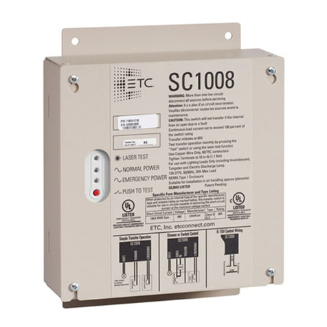
circuits, such as phase-dimmed circuits, should use the ETC
SC1008 branch circuit emergency lighting transfer switch
(BCELTS). For more information, visit the ETC website:
etcconnect.com/SC1008.
Installation Requirements
The ALCR-DIN is designed to be permanently installed on a 35mm
(1.3in) DINrail that complies with DIN 43880 and EN 60715.
After you install the Automatic Load Control Relay, configure the time
delay. See
Configure a Time Delay on page6
.
WARNING: This device utilizes high voltage and should
only be installed by a qualified installer or electrician.
Follow all local codes for installation. Before terminating
the AC power wiring verify that the breakers for the
normal power and emergency power are in the off position
and follow the proper lockout/tag out procedures required
by NFPA Standard 70E.
AVERTISSEMENT : RISQUE DE DÉCHARGE ÉLECTRIQUE! Cet
appareil utilise une haute tension et ne doit être installé
que par un installateur qualifié ou un électricien. Suivez
tous les codes locaux pour l'installation. Avant de raccorder
le câblage du courant alternatif, vérifiez que les
disjoncteurs pour l'alimentation normale et pour
l'alimentation de secours sont en position d'arrêt et suivez
les procédures de vérouillage/étiquetage prescrites par la
norme NFPA 70E.
ALCR-DIN Page 2 of 12 ETC

ETC Installation Guide
ALCR-DIN
Important Safeguards
When using electrical equipment always follow basic safety
precautions, including:
• READ AND FOLLOW ALL SAFETY INSTRUCTIONS. SAVE THESE
INSTRUCTIONS.
• Install this unit to an approved electrical enclosure only. This
emergency device must be installed in locations and at heights
where it will not readily be subjected to tampering by
unauthorized personnel.
• The use of accessory equipment not recommended by the
manufacturer may cause an unsafe condition.
• Do not use this equipment for other than intended use.
WARNING: For indoor use only! Must install to an
electrical junction box or wireway.
AVERTISSEMENT : Uniquement pour usage d'intérieur!
Doit être installé sur une boîte de raccordement électrique
ou un chemin de câbles.
Note:
Follow applicable NEC and local electrical code
requirements when installing and powering the controller. The
ALCR-DIN must be installed in a suitably insulated or grounded
enclosure, such that live terminals are not accessible.
ALCR-DIN Page 3 of 12 ETC

ETC Installation Guide
ALCR-DIN
Install and Terminate ALCR-DIN
The ALCR-DIN is designed to attach to lighting control panels or electrical
enclosures that are fitted with a DIN rail and connected before the loads
in the circuit.
Remote Activation Input
Normally closed
Normal/Emergency Power In
Normal/Emergency Neutral
Normal/Emergency Power Out
Normal Control (Switch)Sense
Use Copper Wire
Only. Min. 60°C
Conductors
Normal Power Sense
Normal Neutral Sense
Note: Screw terminals
accept a single wire
4–0.05 mm² (12–30 AWG).
Remote
Loop
0–10 V/
FLO
Six screw terminals on the bottom of the device are used to connect
normal sense and emergency power wires. Four screw terminals on the
top of the device are used for the following connections:
• The two terminals on the left have a factory-installed remote
activation input (wire loop jumper) that provides connection to a
remote triggering device (normally closed, dry contact closure, such
as a fire alarm). When the normally closed contact is triggered, the
relay opens activating the emergency lighting.
• The two terminals on the right provide termination of 0–10VDC,
LED driver loads, or fluorescent lighting control.
1. Snap the device onto an installed DIN rail in the upright position at
least 5 cm (2 in) away from any heat-generating devices. Tension
clips on the device provide an audible click when the device is
installed properly.
2. Locate the normal and emergency circuit breaker panels and
disconnect power to the circuits.
3. Terminate the ALCR-DIN to the emergency lighting for the area
controlled.
a. Connect
Emergency Power In
and
Emergency Power Out
wires
to the screw terminals on the device in series with the
emergency lighting.
b. Connect the
Neutral
for the emergency circuit to the
Emergency
Neutral
screw terminal.
ALCR-DIN Page 4 of 12 ETC

ETC Installation Guide
ALCR-DIN
4. Terminate the normal sense wiring leads to the normal lighting and
control device for the area controlled.
a. Connect the
Normal Power Sense
and the
Normal Control
(Switch) Sense
wires to the provided screw terminals.
i.
Note:
To ensure that the emergency lighting connected to
the device turns On in the event of a power loss, you must
connect the Normal Power Sense wires upstream of any
switched control device for the normal lighting loads.
b. Connect the
Normal Neutral Sense
to the provided screw
terminal.
5. If you are connecting to 0–10 VDC or fluorescent lighting loads,
connect to the terminals labeled 0–10 V/ FLO. See
Examples of Use
on page9
for more information.
6. Are you are installing a remote triggering device to remotely
activate the emergency circuit?
• No: Go to
Initial Test on page7
to confirm the connection.
• Yes: See
Remote Activation Input below
for wiring instructions.
7. Restore power to the circuits.
Remote Activation Input
The ALCR-DIN offers a normally closed, dry contact input to
accommodate connection to a fire alarm panel, security system, or test
switch. This input ships from the factory with a blue wire loop (jumper)
connected to two of the top screw terminals. It is a complete loop that
disables remote activation. Do not remove or cut this jumper unless you
are installing a remote triggering device.
Note:
ETC recommends that you power up and test your system
before connecting to a remote device. See Initial Test on page7.
The remote device that triggers the Emergency circuit On must provide a
normally closed, maintained dry contact closure for fire alarm systems.
When the remote device is activated, the contact closure opens and the
contacts force the ALCR-DIN into the emergency On state.
Note:
The remote triggering device, test switch, or emergency
system must be installed within 305 m (1,000 ft) of the Automatic
Load Control Relay when using recommended1mm2(18 AWG)
wire.
1. Remove the wire loop jumper from the Remote Loop In and Remote
Loop Out terminals.
ALCR-DIN Page 5 of 12 ETC

ETC Installation Guide
ALCR-DIN
2. Connect the Remote Loop In and Remote Loop Out terminals on the
ALCR-DIN to the single pole contacts on the remote device or test
switch.
3. Go to
Remote Activation Test on page8
to confirm the connection.
Configure a Time Delay
If your lighting requires a warmup period (for example, for high-intensity
discharge [HID] lamps), you can configure a time delay to keep the
emergency lighting on for a period of time after the normal power is
restored. The default time delay is zero. To configure a longer transition
time follow the steps below.
1. Press the [Option] button on the ALCR-DIN. Both the Status and
Remote LEDs will blink to indicate the current time delay
configured.
2. Press and release the
[Option] button to cycle
through the settings, and
stop when the blink pattern
matches the setting you
want.
3. Wait 10 seconds for the
ALCR-DIN to save the setting
and resume normal
operation.
No. of Blinks Time Delay
1 blink no delay
(default)
2 blinks 10 seconds
3 blinks 30 seconds
4 blinks 10 minutes
5 blinks 15 minutes
Note:
The configured time delay applies when the ALCR-DIN
senses the loss of normal power and switches to the emergency
state and when the emergency state has been triggered by the
remote activation input.
ALCR-DIN Page 6 of 12 ETC

ETC Installation Guide
ALCR-DIN
Power Up and Test
Initial Test
Initial testing of the ALCR-DIN should be done with the
Remote Loop In
and
Remote Loop Out
jumper installed.
1. Turn On the circuit breaker in the emergency panel for the
controlled circuit. The Status LED on the ALCR-DIN illuminates red.
With only the emergency circuit On (normal power should be Off),
the emergency lighting should be activated.
2. Temporarily disconnect and cap the wire lead connected to the
Normal Control Sense
input on the ALCR-DIN. This disables the
normal control function and allows exclusive testing of the
emergency On functionality.
3. Turn On the circuit breaker in the normal panel for the controlled
circuit. The Status LED on the ALCR-DIN illuminates green,
indicating that normal power is present and emergency lighting is
not required.
4. Confirm the automatic emergency On functionality by turning Off
the circuit breaker in the normal panel. The connected emergency
lighting should immediately turn On again and the Status LED on
the ALCR-DIN illuminates red.
5. With the normal circuit breaker secured Off, reconnect the
Normal
Control Sense
wire.
6. Turn On the normal circuit breaker. The ALCR-DIN should now
behave as described in
Examples of Use on page9
.
Note:
If you have installed a remote activation input to the
Automatic Load Control Relay, see Remote Activation Input on
page5 to confirm proper installation and see Remote Activation
Test on page 8 to test the connection.
ALCR-DIN Page 7 of 12 ETC

ETC Installation Guide
ALCR-DIN
Remote Activation Test
With the Remote Activation Input connections made, connected from the
ALCR-DIN and terminated to the single-pole contacts on the remote
device(s) or test switch, test the activation.
• With the remote device in normal mode (contacts closed), the
Status LED on the ALCR-DIN will show green and the device
operates as it did with the factory-installed jumper.
• When the remote device activates, the Status LED shows red,
indicating a switch to emergency state. The ALCR-DIN activates
emergency On mode and the Remote LED shows amber, indicating
remote device control.
Manual Switch Test
The Automatic Load Control Relay features a button to manually switch
the load from normal to emergency power for test purposes.
1. Press and hold the red [Push to Test] button on the front of the
device.
2. Verify the emergency relay closes. This is apparent when the
emergency loads turn on according to your installation.
3. Release the button to return to normal operation.
What does the Test Button do?
The [Push to Test] button simulates the loss of normal power and
bypasses the normal switching of power to the fixture.
ALCR-DIN Page 8 of 12 ETC

ETC Installation Guide
ALCR-DIN
Examples of Use
Note:
In the following diagrams, unused wire pairs are omitted
for clarity of the example installation scenario.
Switch Control Arrangement
• When normal power is present, the switch controls both the normal
and emergency light fixtures.
• When the normal power is lost, when the [Push to Test] button is
pressed, or when the remote activation input is activated (opened),
the emergency fixture turns On full regardless of the switch state.
Emergency Power In (Black)
Emergency Neutral (Gray)
Normal Control (Red)Normal Power Sense (Black)
Normal Neutral (White)
Normal Fixture
Emergency Power Out (Red)
ALCR
Emergency
Fixture
Switch
Backup Arrangement
• When normal power is present, the emergency fixture is turned Off.
• When the normal power is lost, when the [Push to Test] button is
pressed, or when the remote activation input is activated (opened),
the emergency fixture turns On full.
Emergency Power In (Black)
Emergency Neutral (Gray)
Emergency Power Out (Red)
Normal Power Sense (Black)
Normal Neutral (White)
ALCR-DIN
Emergency
Fixture
ALCR-DIN Page 9 of 12 ETC

ETC Installation Guide
ALCR-DIN
Phase Dimmer Control
• When normal power is present, the emergency fixture behaves as a
normally controlled fixture.
• When the normal power is lost, when the [Push to Test] button is
pressed, or when the remote activation input is activated (opened),
the emergency fixture turns On full.
Emergency Neutral (Gray)
Emergency Power In (Black)
Emergency Power Out (Red)
Normal Neutral (White)
Load
Neutral
Line
Normal Power Sense (Black)
Phase
Dimmer
ALCR-DIN
Emergency
Fixture
0–10 V Fixture Control
• When normal power is present and the normal control sense switch
is closed, 0–10 VDC controlled fixture dims according to the control
signal.
• When normal power is present and the normal control sense switch
is open, the 0–10 VDC controlled fixture turns Off.
• Upon loss of normal power, when the [Push to Test] button is
pressed, or when the remote activation input is activated (opened),
0-10 VDC control is bypassed and the fixture turns On to full.
ALCR-DIN
0–10 V
Controller
0–10 V
Emerg. Fixture
0–10 V Non-
Emerg. Fixture
Emergency Power Out
Emergency Neutral
Emergency Power In
Normal Neutral
0–10 VDC Signal0–10 VDC Signal
0–10 V Common
Normal Power Sense
Normal Control Sense
Normal Neutral Sense Switch
Remote Act. Input
ALCR-DIN Page 10 of 12 ETC

ETC Installation Guide
ALCR-DIN
FCC Compliance
Automatic Load Control Relay - ALCR-DIN
(For any FCC matters):
Electronic Theatre Controls, Inc.
3031 Pleasant View Road
Middleton, WI 53562
+1 (608)831-4116
etcconnect.com
This device complies with Part 15 of the FCCRules. Operation is subject
to the following two conditions:(1) this device may not cause harmful
interference, and (2)this device must accept any interference received;
including interference that may cause undesired operation. Visit
etcconnect.com/products for current and complete compliance
information including FCC compliance.
For current and complete compliance information, view the product
datasheets at etcconnect.com. For complete product documentation,
including compliance documentation, visit etcconnect.com/products.
ALCR-DIN Page 11 of 12 ETC

ETC Installation Guide
ALCR-DIN
ALCR-DIN Page 12 of 12 ETC
Other manuals for ALCR-DIN
1
Table of contents
Other ETC Switch manuals

ETC
ETC ERn-NET User manual

ETC
ETC Unison Aero SmartClick UA1001 User manual

ETC
ETC EBDK-SWITCH User manual

ETC
ETC SC1008 Branch Circuit Emergency Lighting Transfer... User manual

ETC
ETC Echoflex Elaho Inspire Station User manual

ETC
ETC Echoflex MBI-2 Series User manual

ETC
ETC Echoflex Keycard Switch Station User manual

ETC
ETC SmartSwitch 24 User manual