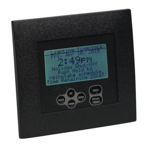
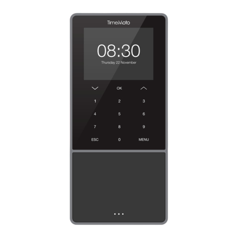
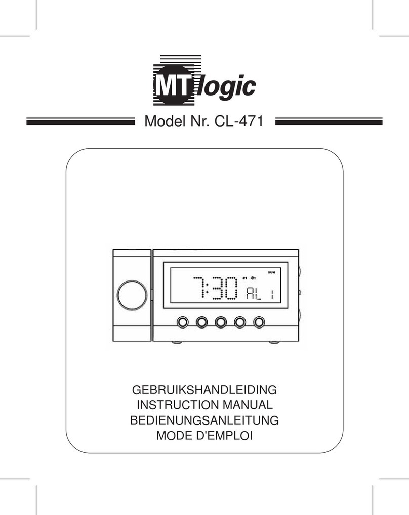
ETC ECHOFLEX Wireless TimeClock User manual

Part Number: 8188M1430-2.0.1 Rev: A
Released: 2021-11
Wireless TimeClock
Configuration Guide
Version 2.0.1

Table of Contents
Table of Contents i
Overview . . . . . . . . . . . . . . . . . . . . . . . . . . 1
Features . . . . . . . . . . . . . . . . . . . . . . . . . . . . . . 1
Document Conventions. . . . . . . . . . . . . . . . . . 2
Help from Technical Services. . . . . . . . . . . . . . 3
Technical Services Department . . . . . . . . . 3
Installation . . . . . . . . . . . . . . . . . . . . . . . . 4
Prepare . . . . . . . . . . . . . . . . . . . . . . . . . . . . . . . 4
Connect the Wiring . . . . . . . . . . . . . . . . . . . . . 5
Install the Station. . . . . . . . . . . . . . . . . . . . . . . 6
Attach the Faceplate . . . . . . . . . . . . . . . . . . . . 6
Replace the Battery . . . . . . . . . . . . . . . . . . . . . 7
User Interface . . . . . . . . . . . . . . . . . . . . . . 8
Keypad Navigation . . . . . . . . . . . . . . . . . . . . . 8
Home Screen . . . . . . . . . . . . . . . . . . . . . . . . . . 8
Getting Started . . . . . . . . . . . . . . . . . . . . 9
Definitions . . . . . . . . . . . . . . . . . . . . . . . . . . . . 9
Organize. . . . . . . . . . . . . . . . . . . . . . . . . . . . . 10
Link and Configure . . . . . . . . . . . . . . . . . . . . 11
Main Menu . . . . . . . . . . . . . . . . . . . . . . . 11
Schedule Events . . . . . . . . . . . . . . . . . . . . . . . 11
Stage an Event . . . . . . . . . . . . . . . . . . . . . 12
Manual Override . . . . . . . . . . . . . . . . . . . 12
Schedule an Event . . . . . . . . . . . . . . . . . . 12

ii Table of Contents
TimeClock Settings . . . . . . . . . . . . . . . . . 16
Set Current Time. . . . . . . . . . . . . . . . . . . . . . . 16
Set Time Style . . . . . . . . . . . . . . . . . . . . . . . . . 16
Set Current Date. . . . . . . . . . . . . . . . . . . . . . . 16
Set Time Zone . . . . . . . . . . . . . . . . . . . . . . . . . 16
Set Latitude and Longitude . . . . . . . . . . . . . . 17
Set Daylight Saving Time . . . . . . . . . . . . . . . . 17
Set Manual DST Dates . . . . . . . . . . . . . . . . . . 17
Set Sweep Interval . . . . . . . . . . . . . . . . . . . . . 17
Set Timed Hold . . . . . . . . . . . . . . . . . . . . . . . . 18
Set Flick Warn . . . . . . . . . . . . . . . . . . . . . . . . . 18
Show Seconds . . . . . . . . . . . . . . . . . . . . . . . . . 18
Restore Defaults . . . . . . . . . . . . . . . . . . . . . . . 19
Holiday Shut-Off . . . . . . . . . . . . . . . . . . 20
Configure Holiday Groups . . . . . . . . . . . . . . . 20
Set Holiday Shut-Off Duration . . . . . . . . . . . 20
Manage Controllers . . . . . . . . . . . . . . . . 21
Link or UnLink . . . . . . . . . . . . . . . . . . . . . . . . 21
Linked Controllers . . . . . . . . . . . . . . . . . . . . . 21
Configure Controller. . . . . . . . . . . . . . . . . 21
Hold . . . . . . . . . . . . . . . . . . . . . . . . . . . . . 22
Timed Hold . . . . . . . . . . . . . . . . . . . . . . . . . . . 23
Indefinite Hold . . . . . . . . . . . . . . . . . . . . . . . . 23

Table of Contents iii
Recall Preset . . . . . . . . . . . . . . . . . . . . . . 23
Menu Structure . . . . . . . . . . . . . . . . . . . 24
Numbered Elements . . . . . . . . . . . . . . . 25
Configured Scenes . . . . . . . . . . . . . . . . . . . . 25
Configured Events . . . . . . . . . . . . . . . . . . . . . 26
Configured Groups . . . . . . . . . . . . . . . . . . . . 27
Compliance . . . . . . . . . . . . . . . . . . . . . . . 28
FCC Compliance . . . . . . . . . . . . . . . . . . . . 28
ISED Compliance. . . . . . . . . . . . . . . . . . . . 28
Conformité ISDE . . . . . . . . . . . . . . . . . . . . 28

1Wireless TimeClock Configuration Guide
Overview
The Wireless TimeClock (WTC) provides effortless time-based control for your
Echoflex solution.
Its comprehensive event scheduling capabilities, powerful grouping features,
and masking logic maximize energy efficiency to meet Title 24, IECC, and
ASHRAE-90.1 energy requirements.
The six-button user interface and large back-lit display allow for simple setup
and operation.
This guide describes the procedures to install and configure the WTC for use
with linked devices that are part of an Echoflex solution. The product package
includes the TimeClock, 24 V power pigtail, a battery, four screws, eight
receptacle spacers, and two WAGO®connectors.
Features
• Create and control 15 different Scenes for up to 24 Groups
• Schedule and connect up to 50 Events across 24 separate Groups
• Schedule temporary configuration settings
• Link and Group up to 20 controllers
• Meets California Title 24, IECC, and ASHRAE 90.1 requirements
• Astronomical timeclock schedule with before/after sunset or sunrise
calculation based on latitude/longitude settings
• 24-hour real-time clock with user configurable Daylight Saving Time
• Four recurrence settings: every day, weekdays, weekends, day of week
• Hold feature suspends scheduled Events for up to two hours
• Simple manual control of Scenes with overrides
Note:
Grouping controllers and editing the default lighting
levels that create Scenes are features that can only be
configured during pre-commissioning or with Garibaldi
Pro software. Contact Echoflex for more information.
Wireless TimeClock Configuration Guide 2
• Resumes program automatically after power loss
• Backlit graphical LCD display
• Mounts in industry-standard two-gang electrical box
Document Conventions
Echoflex's user documentation is designed for print or electronic use.
Cross-references highlighted in this document are links to the referenced
section of the guide.
Configuration parameters are emphasized in italics. Switch actions (ON/OFF)
and relay events (lights ON/OFF) are written in ALL CAPS. Button names
appear in [Brackets] and key terms in the interface appear in Bold.
This guide uses the following conventions to alert you to danger or important
information. Please email comments about this guide to:
TechComm@etcconnect.com.
Note:
Notes are helpful hints and information that is
supplemental to the main text.
CAUTION:
A Caution statement indicates situations where there
may be undefined or unwanted consequences of an
action, potential for data loss or an equipment problem.
WARNING:
A Warning statement indicates situations where
damage may occur, people may be harmed, or there
are serious or dangerous consequences of an
action.
WARNING:
RISK OF ELECTRIC SHOCK! This warning statement
indicates situations where there is a risk of electric
shock.

3Wireless TimeClock Configuration Guide
Help from Technical Services
If you are having difficulties that are not addressed by this document, contact
Echoflex support at service@echoflexsolutions.com or the main website at
echoflexsolutions.com. If none of these resources are sufficient, contact
Technical Services directly at the office identified below.
When calling for help, take these steps first:
• Prepare a detailed description of the problem
• Be near the equipment for troubleshooting
• Find your notification number if you have called in previously
Technical Services Department
3031 Pleasant View Road
Middleton, WI 53562
800-775-4382 (USA, toll-free)
+1-608 831-4116
service@echoflexsolutions.com

Wireless TimeClock Configuration Guide 4
Installation
Prepare
To ensure optimal function, consider the installation environment and the
following guidelines:
• For indoor use only. Operating temperature 0°C to 40°C
(32°F to 104°F), 5%–95% relative humidity (non-condensing).
• High density construction materials and large metal appliances or
fixtures in the space may disrupt wireless reception.
• Install the WTC within range of linked lighting controllers, 24 m (80 ft)
unobstructed view. Consider adding a repeater to extend the wireless
signal, if required.
• External antenna options include extension cables and a magnet-mount
antenna for installation locations with poor wireless reception.
• Can be surface-mounted or flush-mounted in an industry standard
two-gang electrical box (not provided). The box must be installed plumb
and square. Ensure it is clean and free of obstructions to accommodate
the cable if using an external antenna.
• Provide a 24 V power supply connection to the target two-gang
electrical box.
• Pull the plastic tab to activate the installed CR2032 battery. The battery
is not required to run the WTC, it is only used to maintain the time in
case of a power outage.
Note:
Installation must follow all national and local codes for
electrical equipment.
Note:
An External Antenna Extension Kit is sold separately
through Echoflex, part number 8186K1001. Contact
Echoflex for more information.

5Wireless TimeClock Configuration Guide
Connect the Wiring
The WTC ships with a 24 V power terminal strip with wire pigtail, spacers, and
all required screws and connectors for the installation.
The antenna jumper is set to use the internal whip antenna by default, position
2 and 3. If your installation uses the external antenna option, adjust the
jumper position to 1 and 2 (move it left).
1. Pull the two 24 V power supply wires into the electrical box and strip
11 mm (7/16 in) of insulation.
2. Strip 11 mm (7/16 in) of insulation from both the red and black pigtail
wires.
3. Use the WAGO connectors provided to connect the power pigtail and the
power supply output wires. Use one WAGO for the red wire (positive +)
and one for the black wire (negative -). Open the terminal levers on the
WAGO connector and insert the power supply wire and the lead from the
pigtail into the terminals, then close the levers. Tug the wires to ensure
they are secure.
4. Connect the two-pin connector to the power pigtail receptacle on the
station.
5. If using the external antenna option, connect the patch cable to the
RP-SMA connector port. Ensure the jumper is set to position 1 and 2.
Note:
If using the External Antenna Extension kit, the
connection for the flexible coaxial patch cable (part
number N1124) may be outside the electrical box.
24 V power pigtail
receptacle
RP-SMA connector
port for external
antenna
Jumper setting
for antenna
Internal whip
antenna

Wireless TimeClock Configuration Guide 6
Install the Station
Receptacle spacers are provided to help align the station flush against the wall
in flush-mount applications. The spacers are not required when installing the
station into a surface-mount electrical box.
1. Insert the station and the connected wiring in the electrical box.
2. Fold spacers as needed to achieve the thickness required to fill the gap
between the station, wall surface, and the electrical box.
3. Secure the station in place using the four screws provided. If using
spacers, insert the screws through the spacers.
4. Use a level to align the station square to the wall. Adjust spacers as
required so the faceplate fits flush against the wall.
5. Shape the internal whip antenna into a “J” or hockey stick with the tip
pointing up an away from the metal mounting bracket. Ensure the tip of
the antenna is not touching any metal.
Attach the Faceplate
The faceplate is secured to the
station with two magnets at the
bottom.
1. Hook the top of the faceplate
into the tabs at the top of
station’s metal plate.
2. Ensure the whip antenna is not
pinched and the tip is not
touching any metal.
3. Close the bottom of the
faceplate to engage the
magnets and secure it in place.
Faceplate hooks
Spacers
Spacers
Magnet contacts

7Wireless TimeClock Configuration Guide
Replace the Battery
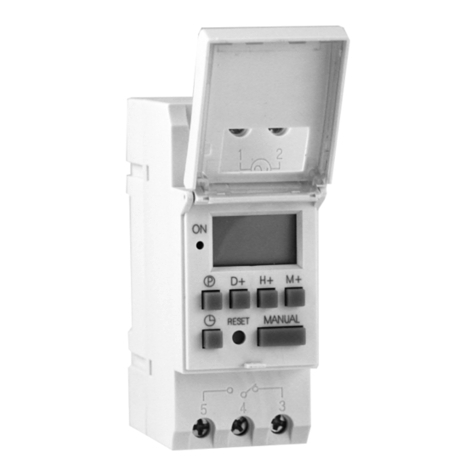
The CR2032 battery is only used to maintain time in case of a power outage.
Estimated battery life is up to 10 years, depending on usage. To replace the
battery:
1. Remove the faceplate and unscrew the station from the electrical box to
access the back cover.
2. Unplug the pigtail connection from the receptacle, and the RP-SMA
connector, if using.
3. Insert a screwdriver into one of the holes on the side of the back cover
and pry carefully to free the side. Repeat to free the other side. The back
cover folds into three sections.
4. Remove the cover and insert the new battery under the clip with the
positive side (+) up.
5. Replace the cover, restore the connections, reinstall the station, safely
position the whip antenna, and attach the faceplate.
Note:
To avoid unwanted tampering, a two-gang locking cover
is sold separately through Echoflex, model no. SL-2.
Contact Echoflex for more information.
Battery

Wireless TimeClock Configuration Guide 8
User Interface
The display screen is backlit for easy viewing. Press any button on the keypad
to wake the display and backlight. The backlight sleeps after two minutes of
inactivity.
Keypad Navigation
The user interface has an easy-to-use keypad that includes [Up], [Down],
[Back], and [Enter] buttons to navigate configuration settings (see Main Menu
on page 11). The [Hold] button suspends scheduled Events (see Hold on page
22). The [Recall Preset] button activates defined Scene settings (see Recall
Preset on page 23).
Use the [Up] or [Down] buttons to
scroll through menu levels and
options. Use the [Enter] button to
make a menu selection or to set a
configuration parameter. Press
[Back] to exit a menu or cancel a
change without saving.
Home Screen
The Home Screen displays the date and time and system messages, such as
active Holds. It reverts to dimmed sleep mode after two minutes of keypad
inactivity. Press the [Back] button to wake up the Home Screen.
To change the display contrast, press and hold the [Back] button while tapping
[Up] or [Down] on the keypad.
To return to the Home Screen from any menu level, press [Back] until you
completely exit the menu structure.
Mon, Aug 2, 2021
4:20 p m
v1.0.0
Lighting TimeClock Current date and time
Software version
System status

9Wireless TimeClock Configuration Guide
Getting Started
The WTC is part of a designed solution made up of connected devices. It
coordinates the lighting controllers by setting levels, recalling lighting scenes,
and can send instructions to ignore linked sensors or stations.
In addition to other settings, Echoflex controllers each have 15 preset light
intensity levels that are configurable from 0% to 100%, and one preset level
reserved for OFF that is not configurable.
Presets are used to create lighting scenes. For Echoflex controllers that support
tunable white fixtures, presets can be used to set the color temperature as part
of the lighting scene.
A lighting space may be divided into multiple zones and include different types
of fixtures. To provide independent control of each zone or class of fixture,
Echoflex controllers can be assigned to logical Groups. Up to 24 Groups are
supported and each controller can be a member of one or more Groups.
Controller Groups can be set independently or in combination with one
another. In Echoflex architecture, lighting scenes are created by instructing
Groups of controllers to activate one of their presets. The WTC can be used to
recall scenes on a schedule. Multi-Scene Stations (MSS) can be used to recall
scenes manually.
Definitions
Scene – a lighting scenario that describes the overall lighting set in a space. A
scene may require lighting fixtures to be ON at different intensity levels, OFF,
or color temperature values to be set. A space may have several different
scenes. For example, a conference room could have scenes for general
lighting, presentations, movie viewing, and video conferencing.
Preset – a configured setting that stores a value between 0% and 100% in an
Echoflex controller. Echoflex controllers have configurable 15 presets (and one
reserved for zero, or OFF). At an installation site, controller presets can be
configured using Garibaldi Pro software.
Group – a logical group of Echoflex controllers, numbered between 1 and 24.
Echoflex controllers can be member of one or more of the 24 Groups.
Event – a scheduled lighting instruction for a Group of controllers.
Note:
Garibaldi Pro software is required to configure presets
and to group controllers. Controllers are associated with
Group 1 by default.

Wireless TimeClock Configuration Guide 10
Organize
Proper planning is required to design the lighting effects and schedules for
different Scenes that light a space.
Consider creating a plan to manage the lighting effects you want to control.
You may need different plans for different building types, like a lecture hall,
office, or school. The settings are organized with simple numbering systems
that can be customized for every installation.
Element Description Example Usage
Events
1–50
A defined lighting
Event for a specified
Group that runs on a
configured schedule.
Consider creating a pattern, such as:
Scheduling ON/OFF Events: 1–10
Scheduling Scenes: 11–26
Device Masking: 27–40
Special: 41–50.
Groups
1–24
A defined area or role
to coordinate selected
controllers. Each
controller is associated
with Group 1 by
default.
Controllers can be associated with one or
more Groups. Groups should be
associated with common areas in a facility
that include several controllers. Create a
name to identify each Group, for
example:
Group 1 = Reception
Group 2 = Open Office Area
Group 3 = Corridors
Group 4 = Exterior Lights
Scenes
1–15
A defined lighting level
that can be used in a
scheduled Event or
manually activated.
An Event can use a Scene number to set
the lighting level on a schedule. Buttons
on a Scene Station can be used to
manually activate a Scene. A recalled
preset combines a Group number (target
controllers) and a Scene number to create
the lighting effect.
Note:
Consider recording the assignments that you create for
each numbered element. See Numbered Elements on
page 25.

11 Wireless TimeClock Configuration Guide
Link and Configure
The WTC must be linked to the target lighting controllers to create lighting
effects using scheduled Events and Scenes. Recommended steps:
• Configure TimeClock defaults, see TimeClock Settings on page 16.
• Identify and Link the target controllers, see Link or UnLink on page 21.
• Determine the Groups required for the space you want to control.
• Determine each controller’s preset lighting levels for the Scene.
• Define and schedule Events, see Schedule an Event on page 12.
The WTC can be Linked to a project’s lighting controllers using Echoflex
pre-commissioning services. Contact customer service for information about
pre-commissioning services.
Main Menu
The Main Menu provides access to set up and configure Events, settings, and
manage linked controllers. Press [Up], [Down], or [Enter] to wake up and
navigate the Main Menu screen.
To navigate the menu options, press [Up] or [Down] to scroll and press [Enter]
to make a selection. Press [Back] to cancel without saving.
For an example of submenus and screen navigation, see Menu Structure on
page 24.
Schedule Events
The WTC supports up to 50 programmed Events that can be scheduled to
occur and re-occur every day, on weekdays, on weekends, or on individual
days of the week.
Events can be set to occur at a particular time
of day by setting a specific time, or by setting
an offset time based on an astronomical
event, such as before sunrise, after sunrise,
before sunset, or after sunset. Events can also
be connected to create a compound Event,
where one Event triggers other Events to
execute, see Stage an Event on page 12.
An Event is controlled by the type of Action selected. Types of Action include:
Main Menu
Schedule Events
TimeClock Settings
Holiday Shut-Off
Manage Controllers
Aug 2, 2021 4:20pm
Main Menu
Schedule Events
TimeClock Settings
Holiday Shut-Off
Manage Controllers
Aug 2, 2021 4:20pm

Wireless TimeClock Configuration Guide 12
•None - identifies an Event number that has no defined Action; it has no
effect. The factory default for all Event numbers is None.
•Mask - defines an Event where controllers in a Group ignore input from
a type of transmitter. For example, a Mask will ensure that vacancy
detected by an occupancy sensor does not turn the lights OFF during
normal office hours.
•Scene - defines the light intensity and color temperature for an Event
managed by a designated Group. The effect is created by activating
configurable presets stored in each controller. If a controller does not
support light intensity and color temperature features, its lighting
control in an Event is either ON or OFF.
•ON to Level - defines the light intensity or color temperature for an
Event managed by a designated Group. For example, ON to Level can be
used to set the output for controllers in a Group to 50%.
•OFF - defines an Event that turns OFF controllers in a designated Group.
Stage an Event
The staged Event feature can be used to connect multiple Events in a series.
This enables the triggering of one Event to activate a sequence of other Events.
For example, you can create Event 1 to set a Scene for a Group on Tuesday
mornings. If you want another Scene for another Group at the same time,
defined as Event 2, you can simply enter Event 2 as the Next Event in the
definition for Event 1.
Using this feature effectively requires some organized planning, so consider
using the planning guide. See Configured Events on page 26.
Manual Override
Events are created on a schedule for a purpose and are intended to stay in
effect. However for safety reasons, any active Event can be replaced by a
manual control setting. For example, janitorial staff turn the lights ON. The
Sweep feature repeats the Event setting to remove any manual overrides. See
Set Sweep Interval on page 17. Even without a Sweep, manual control
settings are replaced by the next scheduled Event, unless there is an active
Hold in place.
Schedule an Event
1. Select Schedule Events from the Main Menu and press [Enter] to modify
the Event Number.
2. Press [Up] or [Down] to scroll the numbers, and press [Enter] to select.
3. Press [Down] to focus on Action and press [Enter] to modify.
4. Use [Up] or [Down] to scroll through the actions: Mask, Scene, ON to
Level, OFF, and None. See the following steps based on your selection:

13 Wireless TimeClock Configuration Guide
Define Settings for a Mask
1. Press [Enter] to select Mask as the Event
Action.
2. Select a Group Number from 1 to 24,
and press [Enter] to select.
3. Select a Mask Type for the controller to
lockout and press [Enter].
- Switch, Photo, or Occupancy
4. Enter the hours and minutes for the Mask Duration to be in effect,
maximum 17 hours 59 minutes.
5. Select a type of day for Recurrence.
- None, Every Day, Weekdays, Weekends, or day of the week
Select None if the Event is going to be used in a compound Event. If not
None, define the setting for When and Time or Offset.
6. Select a reference for When.
- Time of Day, or an astronomical setting (Before/After Sunrise/Sunset)
7. Set a Time or an Offset, depending on the When option you selected.
• If Time of Day was selected, specify the Time in hours and minutes
00h:00m (am or pm).
• If an astronomical setting was selected, specify the Offset hours
and minutes from the astronomical setting. For example, if Before
Sunset is selected, choose how long before sunset you want the
Event to execute. The Next Time is calculated and displayed in
parentheses (##:## am).
8. Select Next Event and enter an Event Number from 1–50, if you want to
create a compound Event.
Define Settings for a Scene
1. Press [Enter] to select Scene as the Event
Action.
2. Select a Group Number from 1 to 24,
and press [Enter] to select.
3. Select a Scene Number from 1 to 15,
and press [Enter] to select.
4. Select a type of day for Recurrence.
- None, Every day, Weekdays,
Weekends, or day of the week
Select None if the Event is going to be used in a compound Event. If not
None, define the setting for When and Time or Offset.
Note:
To Mask multiple transmitters, create a separate Event
for each Mask Type.
Schedule Event
Event Number: 2
Action: Mask
Group Number: 24
Mask Type: Switch
Mask Duration: 0h00m
Recurrence Tuesday
When: Time of Day
Time: 12:00am
Next Event: 9
Schedule Event
Event Number: 3
Action: Scene
Group Number: 4
Scene Number: 10
Recurrence Tuesday
When: Time of Day
Time: 12:00am
Sweep: Enabled
Sweep Duration: 12h00m
Next Event: None

Wireless TimeClock Configuration Guide 14
5. Select a reference time of day for When.
• Time of Day, or an astronomical setting (Before/After Sunrise/
Sunset)
6. Set a Time or an Offset, depending on the When option you selected.
• If Time of Day was selected, specify the Time in hours and minutes
00h:00m (am or pm).
• If an astronomical setting was selected, specify the Offset hours
and minutes from the astronomical setting. For example, if Before
Sunset is selected, choose how long before sunset you want the
Event to execute. The Next Time is calculated and displayed in
parentheses (##:## am).
7. Select disable or enable Sweep to reapply Event settings, removing any
manual settings.
- Enable or Disable.
- If enabled, specify the Sweep Duration 0h00m, maximum 24h59m.
See Set Sweep Interval on page 17 to set the interval.
8. Select Next Event and enter an Event Number from 1–50, if you want to
create a compound Event.
Define Settings for ON to Level
1. Press [Enter] to select ON to Level as the
Event Action.
2. Select a Group Number from 1 to 24,
and press [Enter] to select.
3. Select a Level from 0% to 100%, and
press [Enter] to select.
4. Select a type of day for Recurrence.
- None, Every day, Weekdays, Weekends, or day of the week
Select None if the Event is going to be used in a compound Event. If not
None, define the setting for When and Time or Offset.
5. Select a reference time of day for When.
- Time of Day, or an astronomical setting (Before/After Sunrise/Sunset)
6. Set a Time or an Offset, depending on the When option you selected.
• If Time of Day was selected, specify the Time in hours and minutes
00h:00m (am or pm).
• If an astronomical setting was selected, specify the Offset hours
and minutes from the astronomical setting. For example, if Before
Sunset is selected, choose how long before sunset you want the
Event to execute. The Next Time is calculated and displayed in
parentheses (##:## am).
7. Select disable or enable Sweep to reapply Event settings, removing any
manual settings.
- Enable or Disable.
- If enabled, specify the Sweep Duration 0h00m, maximum 24h59m.
See Set Sweep Interval on page 17 to set the interval.
Schedule Event
Event Number: 4
Action: ON to Level
Group Number: 6
Level: 5%
Recurrence: Weekdays
When: Before Sunrise
Offset: 1h15m
Next Time: (7:58am)
Sweep: Disabled
Next Event: None

15 Wireless TimeClock Configuration Guide
8. Select Next Event and enter an Event Number from 1–50, if you want to
create a compound Event.
Define Settings for OFF
1. Press [Enter] to select OFF as the Event
Action.
2. Select a Group Number from 1 to 24,
and press [Enter] to select.
3. Select a type of day for Recurrence.
- None, Every day, Weekdays,
Weekends, or day of the week
Select None if the Event is going to be used in a compound Event. If not
None, define the setting for When and Time or Offset.
4. Select a reference time of day for When.
- Time of Day, or an astronomical setting (Before/After Sunrise/Sunset)
5. Set a Time or an Offset, depending on the When option you selected.
• If Time of Day was selected, specify the Time in hours and minutes
00h:00m (am or pm).
• If an astronomical setting was selected, specify the Offset hours
and minutes from the astronomical setting. For example, if Before
Sunset is selected, choose how long before sunset you want the
Event to execute. The Next Time is calculated and displayed in
parentheses (##:## am).
6. Select disable or enable Sweep to reapply Event settings, removing any
manual settings.
- Enable or Disable.
- If enabled, specify the Sweep Duration 0h00m, maximum 24h59m.
See Set Sweep Interval on page 17 to set the interval.
7. Select Next Event and enter an Event Number from 1–50, if you want to
create a compound Event.
Note:
For scheduled OFF Events, consider enabling Flick Warn.
See Set Flick Warn on page 18.
Schedule Event
Event Number: 5
Action: OFF
Group Number: 20
Recurrence Monday
When: Time of Day
Time: 12:00am
Sweep: Enabled
Sweep Duration: 2h00m
Next Event: 18
This manual suits for next models
1
Table of contents
Other ETC Time Clock manuals