ete 2335400-1 User manual

Customer Manual
1 of 83
© 2021 TE Connectivity Ltd. family of companies.
All Rights Reserved.
TE Connectivity, TE connectivity (logo), and TE (logo) are trademarks. Other logos, product, and/or company names may be trademarks of their respective owners.
PRODUCT INFORMATION 1-800-522-6752
This controlled document is subject to change.
For latest revision and Regional Customer Service,
visit our website at www.te.com.
409-35011
1 OCT 2021 Rev D
SAFETY PRECAUTIONS —READ THIS FIRST! .....................................................................2
SAFETY PRECAUTIONS —AVOID INJURY —READ THIS FIRST!......................................3
INTRODUCTION ..................................................................................................................4
SAFETY................................................................................................................................5
Standards.......................................................................................................................5
Ear and eye protection ...................................................................................................5
Safety covers and guards ..............................................................................................6
Power connections.........................................................................................................6
Safety interlocks...........................................................................................................11
Emergency stop switch ................................................................................................14
DESCRIPTION ...................................................................................................................15
Machine overview ........................................................................................................15
Specifications ...............................................................................................................17
Major components........................................................................................................18
RECEIVING INSPECTION AND INSTALLATION .............................................................28
Receiving inspection ....................................................................................................28
Installation ....................................................................................................................34
OPERATION ......................................................................................................................39
Overview ......................................................................................................................39
User interface...............................................................................................................40
Initial startup.................................................................................................................59
Processing ...................................................................................................................59
MAINTENANCE .................................................................................................................71
Daily maintenance........................................................................................................71
Monthly maintenance ...................................................................................................72
Tooling changeover......................................................................................................72
Preventive maintenance...............................................................................................80
TROUBLESHOOTING .......................................................................................................80
REPLACEMENT AND REPAIR .........................................................................................81
Sensor replacement .....................................................................................................82
DECOMMISSIONING.........................................................................................................83
REVISION SUMMARY .......................................................................................................83
Semi-Automatic High Voltage Cable
Preparation Machine (PN 2335400-1)
ORIGINAL INSTRUCTIONS

409-35024
Rev D
2 of 83
SAFETY PRECAUTIONS —READ THIS FIRST!
IMPORTANT SAFETY INFORMATION
NOTE
Keep all decals clean and legible, and replace them
when necessary.
DANGER
ELECTRIC SHOCK HAZARD
This tool is not insulated. When using this unit near
energized electrical lines, use proper personal protective
equipment.
Failure to observe this warning could result in severe
injury or death.
DANGER
SKIN INJECTION HAZARD
Do not use hands to check for oil leaks. Highly
pressurized oil punctures the skin, causing serious
injury, gangrene, or death. If injured, seek immediate
medical help to remove the oil.
DANGER
FIRE HAZARD
Do not use solvents or flammable liquids to clean the
crimping tool. Solvents or flammable liquids could ignite
and cause serious injury or property damage.
Failure to heed these warnings could result in severe
injury from harmful fumes or burns from flying debris.
DANGER
Inspect the tool and jaws/dies before each use. Replace
any worn or damaged parts. A damaged or improperly
assembled tool can break and strike nearby personnel.
Failure to observe this warning could result in severe
injury or death.
CAUTION
—Do not place the tool in a vise. The crimping tool is
designed for hand-held operation.
—Protect the crimping tool from rain and moisture.
Water damages the crimping tool and battery.
Failure to observe these precautions can result in injury
or property damage.
CAUTION
—Do not perform any service or maintenance other
than as described in this manual. Injury or damage to
the tool can result.
Failure to observe these precautions can result in injury
or property damage.

409-35011
Rev D
3 of 83
SAFETY PRECAUTIONS —AVOID INJURY —READ THIS FIRST!
Safeguards are designed into this application equipment to protect operators and maintenance personnel from
most hazards during equipment operation. However, certain safety precautions must be taken by the operator
and repair personnel to avoid personal injury, as well as damage to the equipment. For best results, application
equipment must be operated in a dry, dust-free environment. Do not operate equipment in a gaseous or
hazardous environment.
Carefully observe the following safety precautions before and during operation of the equipment:
Always wear approved eye protection while operating
equipment.
Always wear appropriate ear protection while using
equipment.
Moving parts can crush and cut. Always keep guards in
place during normal operation.
Electrical shock hazard.
Always turn off the main power switch and disconnect
the electrical cord from the power source when
performing repair or maintenance on the equipment.
Never insert hands into installed equipment.
Never wear loose clothing or jewelry that can catch in
moving parts of the equipment.
Never alter, modify, or misuse the equipment.
Do not operate equipment if the guards are removed.
Read and understand this entire document before
using equipment.
CALL TOLL FREE 1-800-522-6752 (CONTINENTAL UNITED STATES AND PUERTO RICO ONLY)
Canada: 1.800.522.6752
China: +86.400.820.6015
Mexico: +52.55.1106.0800
Latin/South America +54.11.4733.2200
Germany: +49.6151.607.1999
UK: +44.0800.267666
France: +33.1.34.20.8686
Netherlands: +31.73.624.6999
The Support Center offers a means of providing technical assistance when required. In addition, Field Service
Specialists are available to provide assistance with the adjustment or repair of the application equipment when
problems arise which your maintenance personnel are unable to correct.
INFORMATION REQUIRED WHEN CONTACTING THE SUPPORT CENTER
When calling the Support Center regarding service to equipment, it is suggested that a person familiar with the
device be present with a copy of the manual (and drawings) to receive instructions. Many difficulties can be
avoided in this manner.
When calling the Support Center, be ready with the following information:
Customer name
Customer address
Person to contact (name, title, telephone number, and extension)
Person calling
Equipment number (and serial number if applicable)
Product part number (and serial number if applicable)
Urgency of request
Nature of problem
Description of inoperative components
Additional information or comments that can be helpful
SUPPORT CENTER

409-35011
Rev D
4 of 83
Figure 1: High Voltage Cable Preparation machine
1
Left side
2
Right side
3
Front
INTRODUCTION
This manual contains the safety, installation, setup, operation, and maintenance procedures for the TE
Connectivity High Voltage Cable Preparation (HV-CP) machine; part number 2335400-1 (Figure 1). Throughout
this manual the left, right, and front side of the machine are defined as shown in Figure 1.
409-35011
Rev D
5 of 83
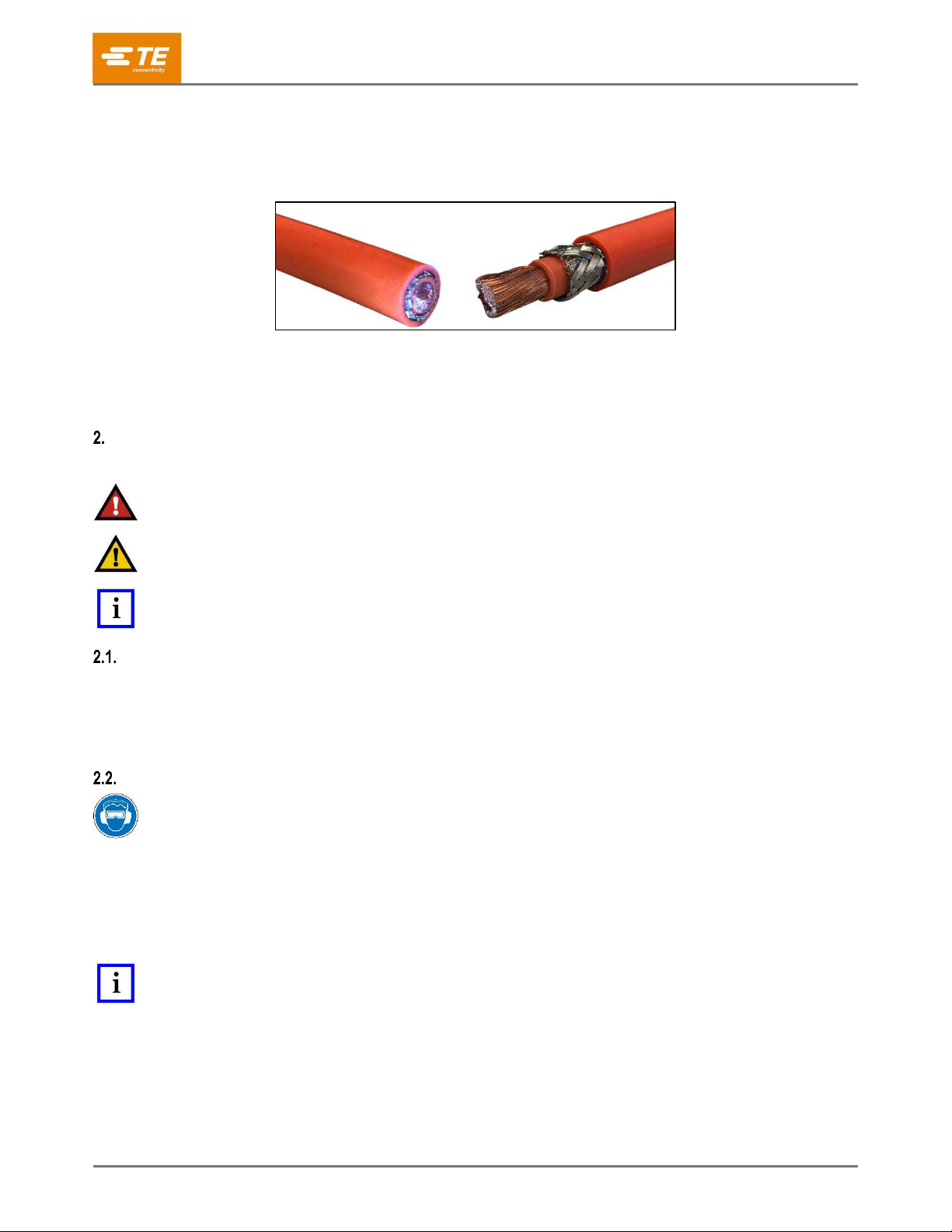
The HV-CP is a semi-automatic, programmable, stand-alone machine designed to strip the cable jacket, braid,
and dielectric foil from round, multi-layer cables (Figure 2) in preparation for the application of crimped
terminals.
Figure 2: Stripping a cable
The machine can process cables with conductor cross-sectional areas ranging from 10mm2to 120mm2,
(8.8mm to 23mm outside diameter).
The machine and tooling have been designed to allow the processing of many cable types and sizes.
SAFETY
When reading this manual, pay particular attention to DANGER, CAUTION, and NOTE statements.
DANGER
Denotes an imminent hazard that can result in moderate or severe injury.
CAUTION
Denotes a condition that can result in product or equipment damage.
NOTE
Highlights special or important information.
Standards
The HV-CP machine is designed to comply with the following standards:
European Machinery Directive 2006/42/EC
European EMC Directive 2014/30/EU
Ear and eye protection
Always wear approved eye and ear protection while operating equipment.
The following applies to the sound level produced by the HV-CP machine:
The sound pressure levels at the operator position are at the infeed < 69.3 dBA, uncertainty K is 6.3
dBA.
The sound power level is 74.0 dBA, uncertainty K, 7.4 dBA.
NOTE
Operating conditions and procedures during sound testing are in accordance with EN 1218-4:2004 + A2:2009. Sound
pressure level at the operator position have been measured in accordance with EN ISO 11202:2010. The sound power level
has been determined in accordance with EN ISO 3746:2010. Uncertainty has been determined in accordance with EN ISO
4871:2009.

409-35011
Rev D
6 of 83
Safety covers and guards
DANGER
Operating the machine with missing or removed components can result in moderate or severe injury, including death.
DANGER
Moving parts can crush and cut.
DANGER
Do not operate the equipment without guards in place.
All safety guards and doors must be in place and securely closed before operating the machine.
Power connections
Main electrical power disconnect
The main electrical power disconnect switch is located on the left side of the machine (Figure 3).
Figure 3: Main electrical power disconnect switch
DANGER
Never enter the electrical enclosure immediately after turning OFF the machine power switch and disconnecting the electrical
power source. High voltage electrical energy can be present in the electrical enclosure. Read the warning label on the
electrical enclosure door before entering the system.

409-35011
Rev D
7 of 83
To provide a safe condition for maintenance or repair, rotate the main power switch to the OFF position
(as shown in Figure 4) and lock it there by inserting a padlock (not included) into the locking locations.
Figure 4: Locking out electrical power
d
= 4-8 mm [0.16-0.31 in]
b
≤47 mm [1.85 in]
CAUTION
Always turn off the main power switch and disconnect the electrical cord from the power source when performing repair or
maintenance on the equipment.
Lock out electrical power when performing maintenance or repair on this equipment.
409-35011
Rev D
8 of 83
Pneumatic connections
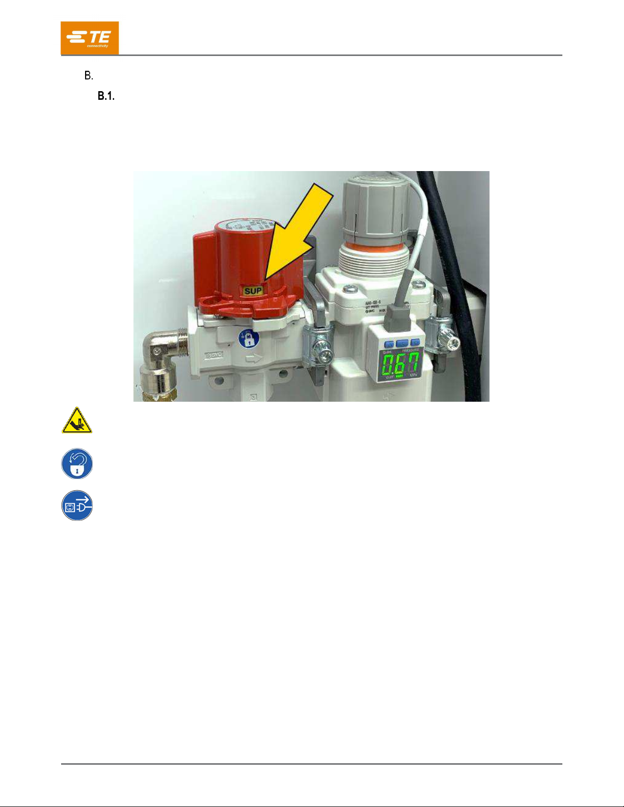
Pneumatic power disconnect
A manually operated main air disconnect valve is located on the left side of the machine, below the
main electrical power switch. The main air valve will exhaust all residual air from the machine when
turned from the Supply (SUP) position (Figure 5) to the Exhaust (EXH) position (Figure 6).
Figure 5: Main air disconnect valve in SUP position
DANGER
Moving parts can crush and cut.
Lock out air supply when performing maintenance or repair on this equipment.
Lock out electrical power when performing maintenance or repair on this equipment.

409-35011
Rev D
9 of 83
The valve can be locked in the EXH position (Lock Out/Tag Out) for maintenance or repair by inserting
a padlock (not included) into the locking location (Figure 6).
Figure 6: Main air disconnect valve in EXH position
1
Indicator shows EXH position
2
Install Lock Out/Tag Out padlock here
409-35011
Rev D
10 of 83
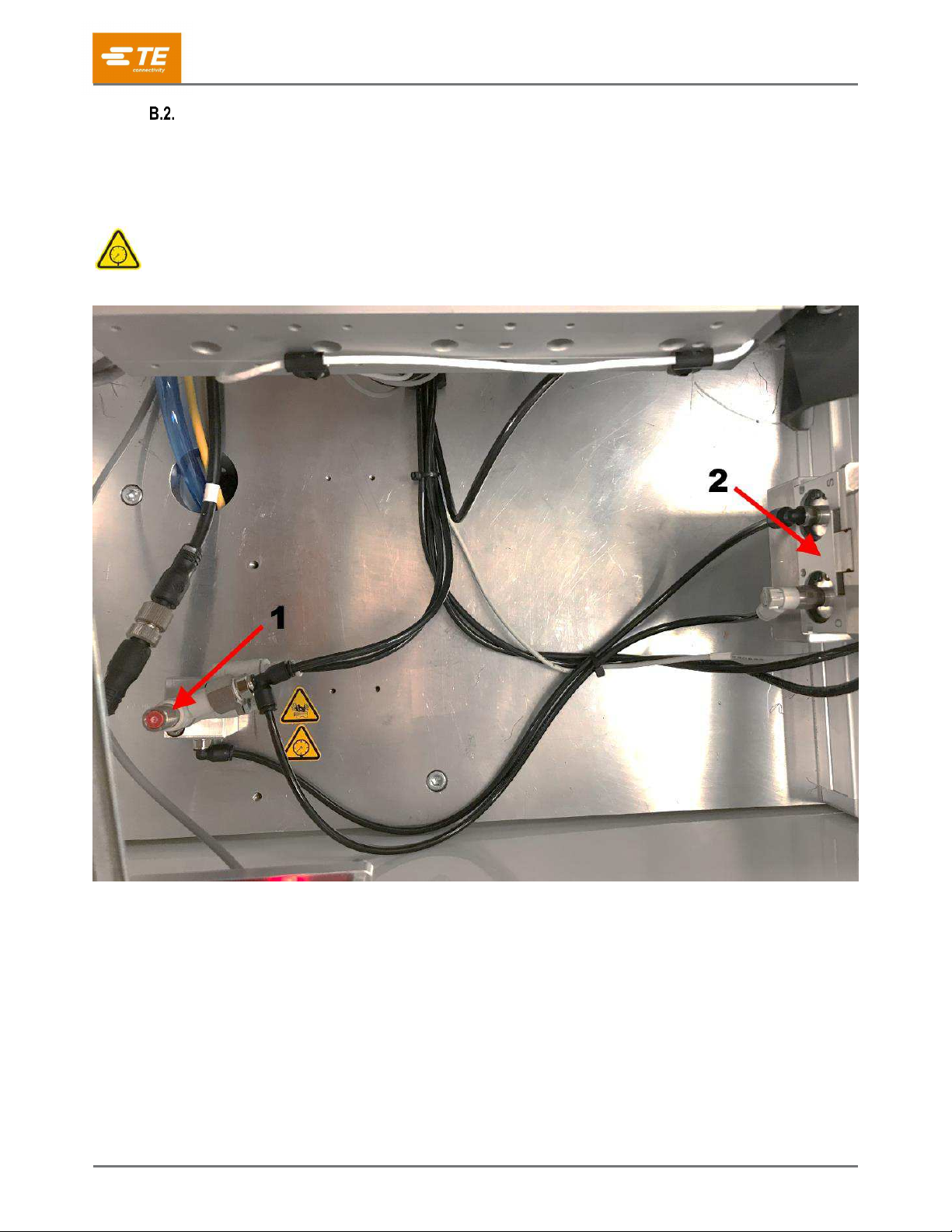
Airlock Valve
If the incoming air supply volume is inadequate, the cable grip force can be reduced during the vacuum
cycle. The airlock valve maintains the grip pressure to prevent the cable from slipping in the gripper
jaws (Figure 7). It also allows the cable grip to be released, if the guard door is opened and the red
button on top of the airlock valve is pressed. The airlock valve is located inside the machine’s sliding
door to the left of the gripper jaws (Figure 7).
CAUTION
The system might be pressurized.
Figure 7: Airlock valve and gripper jaws
1
Airlock valve
2
Gripper jaws

409-35011
Rev D
11 of 83
Safety interlocks
The machine has safety interlocks in two locations:
Under the sliding top guard at the front-left corner of the chassis
The top-left inside corner of the scrap door
Sliding door interlock
The interlock located under the sliding door (Figure 8 and Figure 9) is monitored by a dedicated safety
relay. When the sliding door is opened, the four servo-motor axes are disabled through a Safe Torque Off
(STO) function. In this state, the drives are still energized, but their motor outputs are disabled, the
machine air supply is turned OFF, and residual air pressure is exhausted. This effectively stops all
machine motion. When the sliding door is closed, and if the Emergency Stop relay is energized, the
Interlock safety relay automatically re-enables the STO outputs and reapplies air pressure.
CAUTION
The machine air supply to the valve controlling the scrap vacuum remains energized when the interlock is interrupted.
Disconnect and “Lock Out/Tag Out” the main air supply before performing maintenance or repair.
Figure 8: Top guard interlock closed

409-35011
Rev D
12 of 83
Figure 9: Top guard interlock open

409-35011
Rev D
13 of 83
Scrap door interlock
Interrupting the scrap door interlock (Figure 10) disables the vacuum system. It does not disable the
servos or drop the air pressure.
CAUTION
Do not open or empty the scrap bin while a cable prep cycle is in progress.
NOTE
Resetting an interlock does not automatically restart the machine.
Figure 10: Scrap door safety interlock (open)

409-35011
Rev D
14 of 83
Emergency stop switch
The Emergency Stop (E-STOP) switch is mounted on the top panel of the machine, in the lower left
corner (Figure 11). It is clearly visible, but each operator must note the location and understand the
operation of the E-STOP control in case of an emergency. Pressing the switch does the following:
All four servo motor axes are disabled through a Safe Torque Off (STO) function.
The drives remain powered up, but their motor outputs are disabled.
The air pressure is evacuated.
This effectively stops all machine motion.The E-STOP switch is monitored by an independently dedicated
safety relay.
When pressed, the E-STOP switch latches in the pressed state. In order to continue using the machine,
you must reset the Emergency Stop safety relay.
1. Close the sliding door and the scrap door.
2. Turn the Emergency Stop safety relay clockwise to release it.
3. Press and release the white reset button (Figure 11).
Figure 11: Emergency stop controls
1
Reset button
2
Emergency stop switch

409-35011
Rev D
15 of 83
DESCRIPTION
Machine overview
Rotating stripping head
The HV-CP is fitted with three blades, three cutting wheels, and a mandrel. This offers many advantages,
such as precision centering, braid flaring, and matched toolsets for repeatable processing. The rotating
blades cut the entire circumference of the insulation with precision.
Multi-step stripping
The HV-CP processes multi-layered conductors in steps that can be programmed in any order. The cut
parameters can be independently set and optimized for every level. The stripping machine’s memory
accommodates different conductors and processing parameters.
Operation
The operation of the HV-CP is intuitive. The graphical touchscreen display assists the operator with
setting the processing parameters by creating an article: building a cable profile, setting the run
parameters, and initiating a production run.
Integrated air jets for automatic blade cleaning and an in-line vacuum to remove slugs keep the
processing area clean and efficient. A removable container is located inside the chassis for easy waste
disposal.
Specifications
Table 1: Specifications
Property
Value
Wire cross section (stripping)
10 mm2- 120 mm2
Maximum outer diameter
23.0 mm [0.90 in]
Minimum diameter of inner conductors
6.0 mm [0.24 in]
Maximum outer jacket strip length
80.0 mm [3.15 in]
Maximum braid strip length
70.0mm [2.75 in]
Increments for incision diameter
0.01 mm [0.0004 in]
Increment for stripping length
0.01 mm [0.0004 in]
Article library: maximum number of articles
1500
Sequence function: max number of steps
100
Typical cycle time
30 sec


409-35011
Rev D
17 of 83
Specifications
Table 2: Requirements
Electrical
Voltage
200-265VAC
Frequency
50/60Hz
Circuit
Single phase
Current
10 Ampere
Air
Min machine working pressure
0.62 MPa [90 psi]
Min air volume
570 liters/min [20 cfm]
Max (preferred) machine working pressure
0.69 MPa [100 psi]
Max supply line pressure
0.83 MPa [120 psi]
Ambient temperature for operation
5 - 40 deg C (non-condensing)
Table 3: Physical characteristics
Width
690 mm
Height
1500 mm
Depth
1000 mm
Weight
238 kg [524 lbs.]
NOTE
A customer-supplied 3-conductor power cord, 14 AWG (approx. 2 mm2) is required for the L1, L2, and PE connections. See
section 4.2 for directions for connecting the power cord to the machine.

409-35011
Rev D
18 of 83
Major components
Monitor
The touch screen monitor is the key interface with the machine. The viewing angle can be adjusted (see
Figure 14) by loosening the knobs on either side of the cross-bar, rotating the bar and then tightening the
knobs.
Sliding Door
The sliding door (Figure 14) is the main guard for the mechanisms of the machine. The door has a catch
at the top of its range, allowing for the door to be held open for the transfer of short cables and tooling
changeovers.
NOTE
During the machine cycle, this door must remain fully closed. If the door is opened during a cycle, the cycle stops. This can
result in a defective part.
Figure 14: Monitor and sliding door

409-35011
Rev D
19 of 83
Gripper
The gripper clamps and accurately positions the cable during the cycle. After the sequence is initiated, the
actuator brings the gripper jaws closer together (Figure 15) until the cable is securely held. In response to
the process parameters, the gripper moves the end of the cable to the correct location with respect to the
blades and rollers (Figure 16).
CAUTION
The gripper moves inward and outward from the machine during the cycle, which causes longer cables to move. This also
moves the cable tunnel that extends outside of the machine.
Figure 15: Gripper jaws
Figure 16: Gripper movement

409-35011
Rev D
20 of 83
Airlock valve
The airlock valve (Figure 7) is designed to improve the performance of the machine by maintaining the
grip pressure at all times. If the incoming air supply volume is inadequate, the cable grip force can be
reduced during the vacuum cycle. It also allows the cable grip to be released, if the guard door is opened
and the red button on top of the airlock valve is pressed.
Cutting mechanism
The cutting mechanism is based on relative movement on plates controlled by pulleys and independent
motors. The mechanism has two sets of cutting tools: the contour blades and the cutting wheels (see
Figure 17).
Quick-change cutting arms: Three arms on the rotating mechanism of the machine hold the contour
blades and cutting wheels. These arms rotate to place the blades and wheels for the cutting depth
designated in the program.
Contour blades: Three contour blades are used for cutting the insulation and foil layers of the cable.
Each blade set is designed for a specific cable size (see Table 4 for tooling specifications). The blades are
connected to the cutting arms by a pin and machine screw for easy changeover.
Cutting wheels: Three cutting wheels are used for opening and cutting the braid. The same wheel set
can be used for any cable size.
Blade guides (optional): Blade guides are used to limit the cutting depth of the contour blades on certain
types of cable that are difficult to process due to insulation hardness or other factors. Blade guides are
installed beneath each contour blade. They are generally not required and should only be installed after
consulting with TE Connectivity engineering. When using blade guides, the Blade Guides Installed
selection on the article screen must be set to YES to maintain accurate strip lengths. See step 4 on page
62.
Figure 17: Cutting mechanism
1
Calibration hole
2
Cutting wheel
3
Quick change cutting arm
4
Contour blade
Table of contents
Popular Cables And Connectors manuals by other brands


Paradyne
Paradyne 5030 installation instructions

LEGRAND
LEGRAND TIA 568A quick start guide

Siemens
Siemens SIMATIC NET IE FC RJ45 Plug 4x2 CAT 6A Compact operating instructions

Clearfield
Clearfield FieldSmart FSC PON Cabinets 232 Port installation manual

Staubli
Staubli MC4-Evo 2 Assembly instructions

Opticon
Opticon CRD-19-E4 user manual

Staubli
Staubli ID/S10BV-C Series Assembly instructions

Rockwell Automation
Rockwell Automation 1797-BIC installation instructions

Samsung
Samsung SEA-C101 user manual

Allen-Bradley
Allen-Bradley 1769 CompactLogix installation instructions

OUNEVA
OUNEVA Cu 35-150 2R manual

Philips
Philips SWA2523T Specifications