ETEK ENV-05F-03 User manual

ETEK NAVIGATION, INC.
TEL: 886-2-26860199 FAX: 886-2-26866159
10F., No.105, Xicheng Rd., Banqiao City,
Taipei County 220, Taiwan (R.O.C.)
E-Mail: etek@etek.com.tw http://www.etek.com.
Angular Velocity Sensor
MODEL: ENV-05F-03
User’sManual
Version1.0
Please read this manual before operating the unit
Published: 4.April.2000
© ETEK NAVIGATION, INC.
www.DataSheet4U.com

1/9
Introduction
This angular velocity sensor employs the principle that a Coriolis force results if an angular velocity
is applied to a vibrating object. Murata's unique ceramic bimorph vibrating unit is used as the sensor
element unit, thereby enabling piezoelectric ceramics to be used for both excitation and detection.
The use of this unit simplifies equipment structure and circuit configuration, thus making it possible
to provide outstanding performance.
This sensor can be used for positional control and posture control of a moving object requiring
high-precision measurements.
1. Features
- On - Board mount type for easy PCB installation
- Low height of 23mm capable of being installed in a one DIN size box
2. Applications
- Dead reckoning function in car navigation systems
- Satellite antenna positioning for moving object
- Movement memory for accident recorders
- Other objects requiring angular rate detection with high precision
www.DataSheet4U.com

2/9
3. Specifications
Type ENV-05F-03
Characteristic Symbol Condition MIN. STD. MAX. Unit
Supply voltage Vcc +4.5 +5.0 +5.5 VDC
Current consumption Icc at Vcc=5.0VDC - - 15 mA
Max. angular velocity Omax -1/3PI
(-60) -+1/3PI
(+60) rad/s
(deg/s)
Output Vo angular velocity = 0
at -30~80°C2.150 2.500 2.850 VDC
Scale factor Sv at -10~60°C
at -30~80°C23.0
21.7 25.0
25.0 27.0
28.3 mV/deg/s
Asymmetry CW & CCW - - 3deg/s
Temp. coefficient
Scale factor reference : Ta
at -10~60°C
at -30~80°C-
--
-±5
±10 %FS
Drift at -30~80°C- - 9deg/s
Start up Measure Vo after 5s - - ±1 deg/s/10mi
n
Noise level 10kHz noise - - 20 mVrms
Linearity in the Omax - - 0.5 %FS
Response Phase delay : 90deg -10 -Hz
Dependence on
Supply voltage
Output 0.8 -1.2
Scale factor 0.8 -1.2
Operating temp. range Topr -30 -80 °C
Storage temp. range Tstg -40 -85 °C
Weight - - 20 g
Dimension 11.5(D) x 19.6(W) x 23.2(H) mm
All typical values
Unless otherwise specified, ambient temperature Ta= 25±5deg C, Vcc = 5.0 VDC
Use a sensor output load resistance of 100kohm or more.
www.DataSheet4U.com

3/9
4. Dimensions
11.5
19.6
2.159.05
12.5
2.54
4-2.0
(t=0.3)
23.2
4.0
(1) (2) (3)
3-0.6
(t=0.35)
Unit : mm
Tolerance : ±0.5
Terminals Description
(1) +Supply (input)
(2) Ground (common)
(3) Sensor Output (output)
Y Axis
X Axis
Z Axis (Sense Axis)
CW
CCW
0.3
www.DataSheet4U.com

4/9
5. Installation
1) Install the sensor with the bottom face as reference.
2) Install the sensor vertically with respect to the rotating surface. (90 ± 5 deg)
3) Install the sensor in a location free from vibration.
4) Install the sensor in a place free from substantial variations in temperature.
5) When installing the sensor, solder four tabs and terminals on PCB (t=1.6mm).
6) Observe the following rules. If not, characteristics might vary due to soldering heat.
Soldering iron Flow soldering
Terminal : 350±5deg C, 5s or less.
Tab : 350±5deg C, 10s or less.
Soldering : 250±5deg C, 5s or less.
Preheating :105±10degC,2min.or less.
7) Tabs can be bent only once.
6. Terminal connection
Terminal descriptions
Please refer to page 3 for terminals.
Terminal Symbol Descriptions
1+Vcc Supply voltage (input)
2GND Ground (common)
3Vout Sensor output (output)
6.256.25
2.54
11.2
0.8
18.6
3.0
3-ø1.0
2.15
1.3
Unit : mm
1.3
www.DataSheet4U.com

5/9
7. Connection
1) Operation voltage is +4.5V to +5.5V.
Use stabilized power supply free from surge and ripple.
Confirm power supply polarity before connecting sensor.
2) Output voltage is relative to the angular velocity.
V0 + Sv x O[V]
V0 :Output at angular velocity is 0 [deg/s]
Sv :Scale factor [mV/deg/s]
O: Angular velocity [angular velocity range : -80 ∼+80 deg/s]
3) Use a sensor output load resistance of 100kohm or more.
4) Typical circuit
Note1) The value of this resistance should be 1/1000 or less of impedance of A/D converter
Gyrostar®
ENV-05F
GND
Vout
Vcc
100k ohm
1k ohm
Note1
0.047µF
0.1µF
A/D converter
Impedance
Z >= 1M ohm
+5V
www.DataSheet4U.com

6/9
8. Notice
1) Bias and scale factor drift
Surrounding temperature variation might affect sensor output (bias, scale factor). Sensor should
be mounted where temperature does not vary significantly.
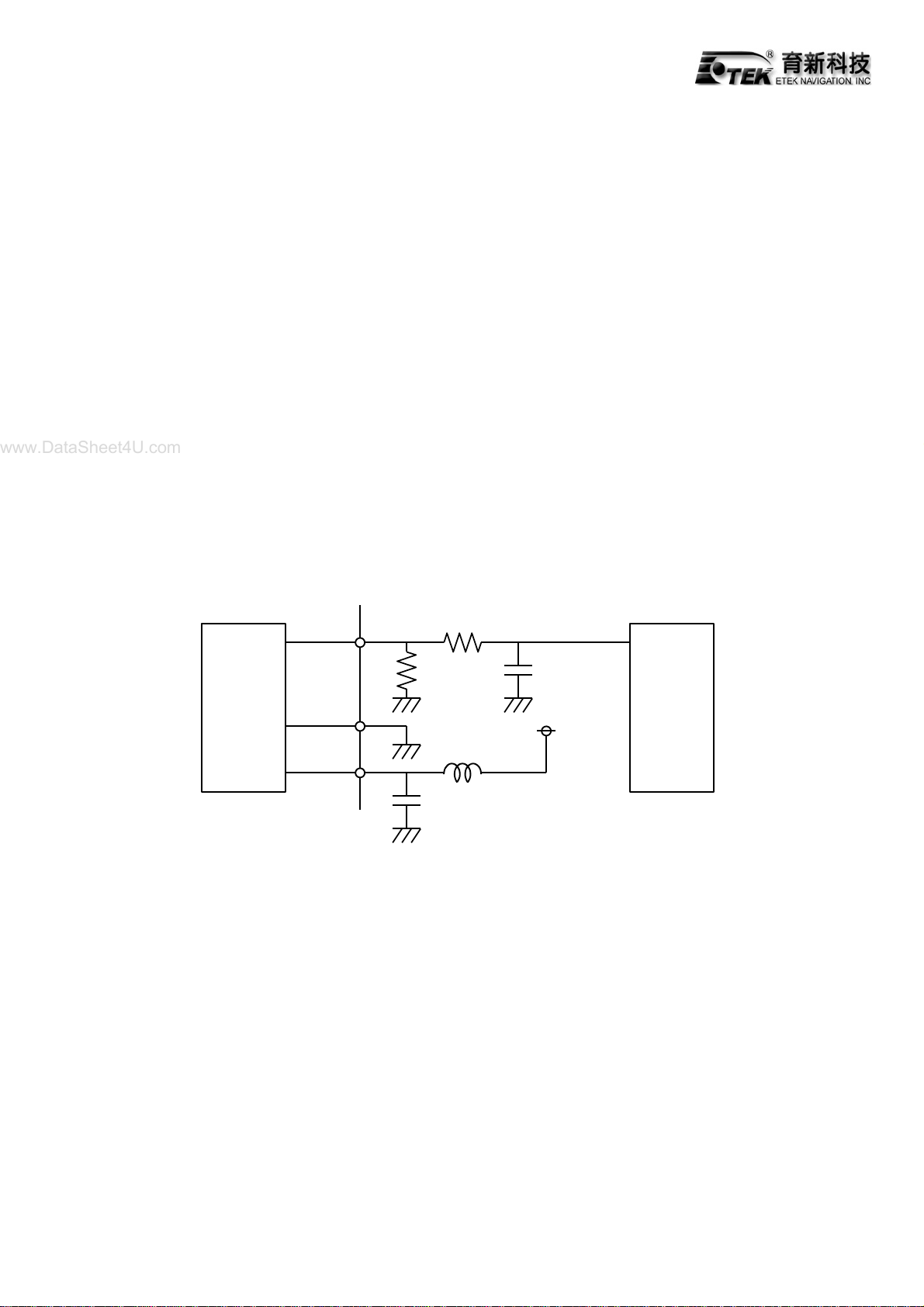
When canceling bias drift, please refer to the following examples.
- Cut DC level of output using HPF (Hi-Pass-Filter) with low cut-off frequency on sensor output.
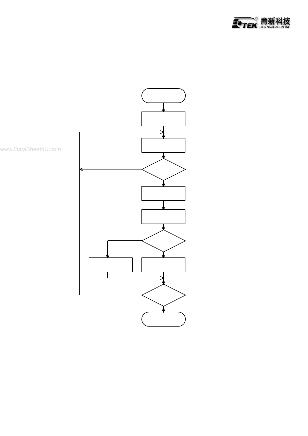
- If bias voltage can be detected just before measurement, replace former bias with it.
( refer to page 8)
2) Gyrostar detects angular velocity. It is possible to derive relative angle variation from integrating
output voltage.
9. Handling
1) Incorrect handling may affect sensor characteristics. Please note the following precautions;
A. Do not subject the sensor to shocks that exceed the rated limit.
B. Do not subject the sensor to a magnetic field exceeding 5000µT (50 G).
C. Do not install or store the sensor in a location in which condensation is likely to form on it.
D. Do not install or store the sensor in a location in which water may splash directly on it.
E. Do not install or store the sensor in a location in which it is likely to be exposed to salt water or
corrosive vapor.
2) Precision electronic parts, such as ICs, are used for the sensor; therefore, it is necessary to take
anti-static measures when handling.
3) Do not wash the sensor, It is not water resistant.
4) Do not remove label.
5) Do not disassemble.
www.DataSheet4U.com

7/9
10. Application
1) When high-precision measurement is required, as in a navigation system, use the output of this
sensor through an A/D converter as shown below.
2) Positive voltage (+) and negative voltage (-) are obtained in the clockwise and counter clockwise
directions, respectively, with the static output as a reference.
3) Always use A/D converter of 12 bits or more. Resolution of A/D converter will affect measurement
accuracy. Please choose a proper resolution according to the application.
4) The sampling frequency used for measurement should be 50 times/sec Min. Sampling frequency
will affect measurement accuracy. Please choose a proper sampling frequency according to the
application.
5) It is possible to derive relative angle variation from integrating the output voltage.
A/D
converter Micro
processor
Sensor
output
+-
Sensor
ENV-05F
www.DataSheet4U.com

8/9
11. Program flow chart for car navigation systems
An example of car navigation systems is shown in below program flow chart.
Correcting location
and direction
Start
Measuring speed
Averaging gyro
output for 1 second
Motion of car
Calculating
location
Renewing offset
End
End
Sampling
No
Yes
Yes
No
Stopping
Moving
Measuring Gyro
output
1 second
passage
www.DataSheet4U.com

9/9
Note
1) Please consult our sales representatives or engineers before using our products listed in this
manual for applications requiring especially high reliability what defects might directly cause
damage to other party’s life, body or property (listed below) or for other applications not specified
in this manual.
1. Aircraft equipment
2. Aerospace equipment
3. Undersea equipment
4. Medical equipment
5. Traffic signal equipment
6. Disaster prevention / crime prevention equipment
7. Data-processing equipment
8. Applications of similar complexity or with reliability requirements comparable to the
applications listed in the above.
2) Product specifications in this manual are as of 4.April .2000 and are subject to change or stop the
supply without notice. Please confirm the specification before ordering any product. If there are
any questions, please contact our sales representatives or engineers.
3) The categories and specifications in this manual are for information only. Please confirm detailed
specifications by checking the product specification document or requesting for the approval
sheet for product specification, before ordering.
www.DataSheet4U.com
Table of contents
Popular Accessories manuals by other brands

S+S Regeltechnik
S+S Regeltechnik THERMASGARD RPTF Series Operating Instructions, Mounting & Installation

Elko
Elko Inels RFDSC-71 manual

senva
senva CHTWL Series installation instructions

Panasonic
Panasonic WJ-PB85L32 instructions

Seiko
Seiko 8T68A Parts catalogue /technical guide

Varec
Varec 4532 Installation and operation manual