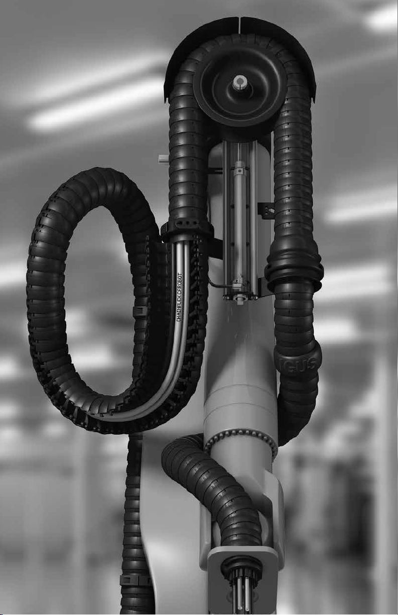
igus triflex R User manual

triflex®
retraction system
assembly instructions
www.igus.com/triflexr
plastics for longer life®
RSE
linear
RS
RSP RSE
Wheel
inside cover - blank
triflex®RSE Wheel 14
triflex®RS Modular 22
RSP shown

Table of Contents
triflex®RSE Linear 6
Linear retractions system that creates
tension through the use of elastic bands
triflex®RSE Wheel 14
Low payload retraction system that uses
elastic bands to create tension
triflex®RS Modular 22
Retraction system that utilizes tension
rods as resistance
triflex®RSP Pneumatic 26
Pneumatically driven retraction system
that allows for tension adjustment
Installation checklist P
Make sure that the ball end of triflex®R is
run in the direction of the tool
1
Remember to use Lock Clips at every fixed bracket
2
Ensure that triflex®R is run straight, not twisted
3
For the end of arm bracket to be
installed correctly, triflex®R
must run into the bracket, not
across the pillow block support
plate
4
Make sure all cables and hoses are strain relieved
individually using tie-wraps or chainfix clamps
5
tie-wraps chainfix
clamps

General Troubleshooting
For system specific troubleshooting see the table at the end of each system
assembly instructions.
Problem Solution
triflex®R comes out of the end of arm bracket 1. Check to make sure Lock Clips are being
used
2. Check to make sure that triflex®R is run in
the correct direction with the ball end run in
the direction of the tool
3. Ensure that the bend radius of the triflex®
R is not being violated during the robot
motion. To relieve this condition, adjust the
end of arm bracket and axis 6 clamp
Cable breaks in the area of the end arm tool 1. Make sure strain relief has been properely
installed at the end of arm bracket
2. Confirm that the service loop from the end
of arm bracket to the tool connection is
sucient
3. Confirm that a torsion rated cable is being
used. If not, contact igus
Cable is coming out of the split opening of triflex®
R TRE
1. Make sure strain relief hs been properely
installed at the end of arm bracket
2. Confirm that the chamber inside triflex®R is
not overloaded
3. Ensure that the cables entering the fixed
end of the system at axis 3 are not pulled
too tight
triflex®R TRE is getting caught on the robot and
is damaged
1. Install a triflex®R protector in any location
that makes contact with the robot arm.
These should be installed 3-5 links apart
wire cutterallen keysscrewdriverwrenches
Tools needed for installation:
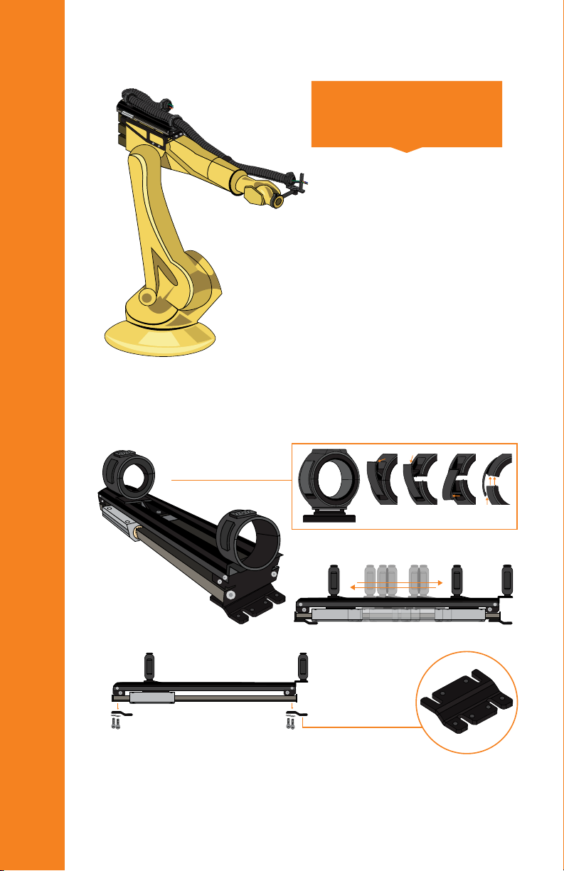
6
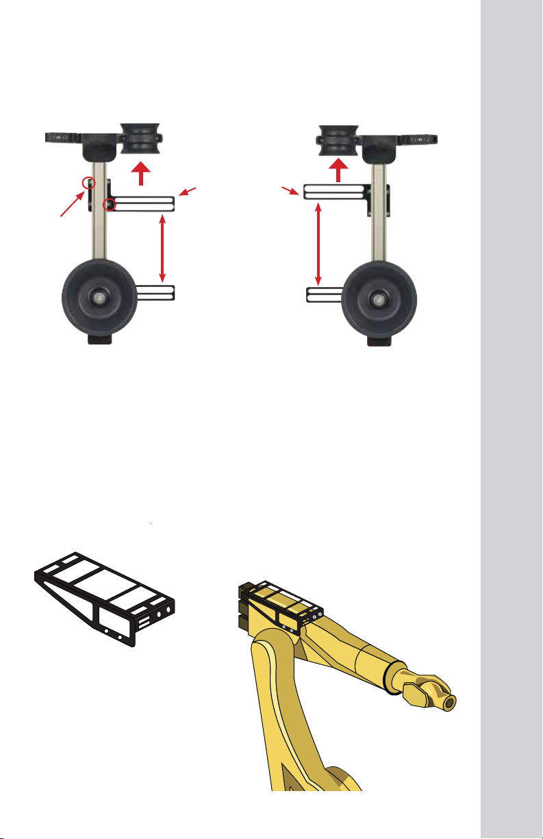
RSE linear retraction system
Tip: Position of mounting feet will need to be adjusted to match the
mounting adapter
Remove mounting feet
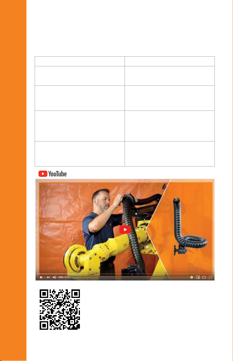
Visit https://toolbox.igus.com and
watch our video: How to install an
igus triflex RSE cable management
system on a six-axis robot
RSE linear installation guide
7
RSE linear installation guide
RSE support bracket
Mount the support bracket to the under-
side of the RSE linear system on either
side
Tip: Mount the support bracket in the middle of the RSE.
(support bracket not available for the 40mm and 50mm size)
Mounting adapter installation example
Note: Each robot model uses
a dierent mounting adapter.
Install the mounting
adapter on the robot
Fasten mounting feet and
adapter together.

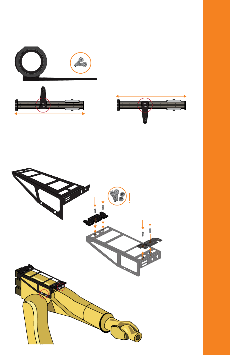
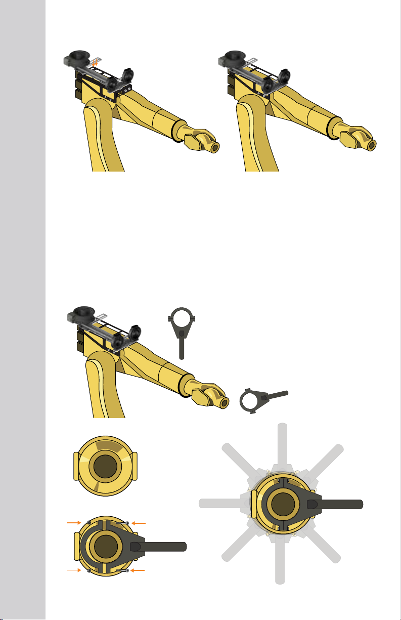
8
Bolts need to be tightened
Note: Tennis rackets available
for most robot models.
Bolts need to
be tightened
uniformly.
Note:
Can be mounted
in any direction
Retraction system installation
Tennis racket (axis 6 clamp) installation
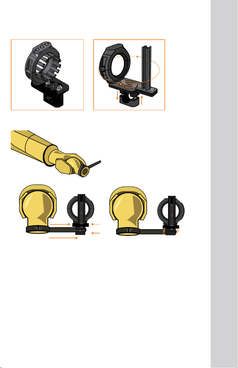
9
Axis 6 bracket installation
Designed with
integrated
profile rail for
CFX clamp
Adjustable in four directions
Tip: Install the bracket as close to the end of the handle as possible and tighten the
bolts equally.
Standard bracket Heavy duty bracket

10
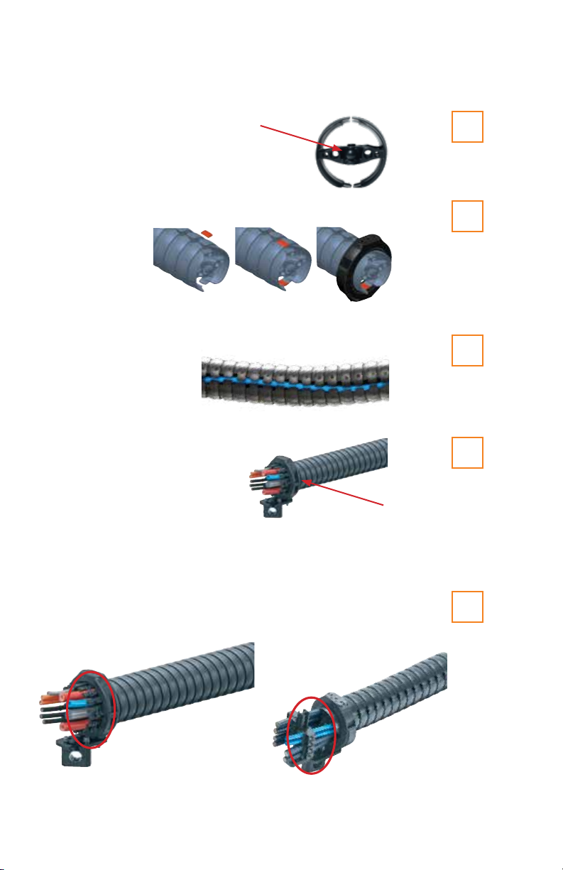
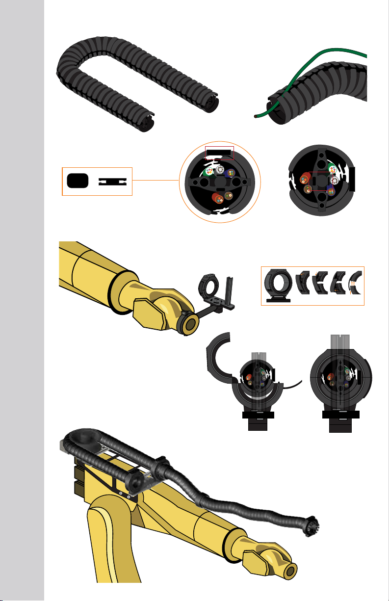
triflex®TRE only - install locking
clips at each fixed bracket
position Important: Ball end of
triflex®R at the EOAT
(End of arm tooling)
Install triflex®R in axis 6
mounting bracket first
Tip: Make sure triflex®R is
not twisted
triflex®R installation
Note: Easy cable installation
possible with triflex®TRE and
TRCF only. If using TRC,
cables will need to be fished
through individually

11
Installing CFX clamps to secure cables
1
2
3
4
5
1
2
3
4
5
1
2
3
4
5
Protector:
To pretension the system, pull the triflex®forward two links
and install a protector at the exit of the moving end
Tip: For quick release protectors, use a flat
head screwdriver to pry the two halves apart
1
2
3
4
5
Installing protectors
Install protectors where triflex®R makes
contact with the robot
triflex®RSE linear
troubleshooting guide
Problem Solution
triflex®R is getting caught at the back of
the rail as it is extending
1. Install RSE support bracket at
midpoint of RSE rail
triflex®R breaks when RSE System is fully
extended
2. Install more triflex®R outside the RSE
System. The motion of the robot is
greater than the available travel of
the RSE System
RSE System does not function 1. Ensure the bands have tension
2. Confirm that the system is free of
debris
3. Reduce the length of triflex®R
outside the RSE System
Carriage slams when the robot returns to
the home position
1. Pull the system forward two links
and install a protector at the exit of
the pass-through bracket thereby
creating a stop
12
Scan the QR code to view the
triflex®RSE Linear assembly video
13
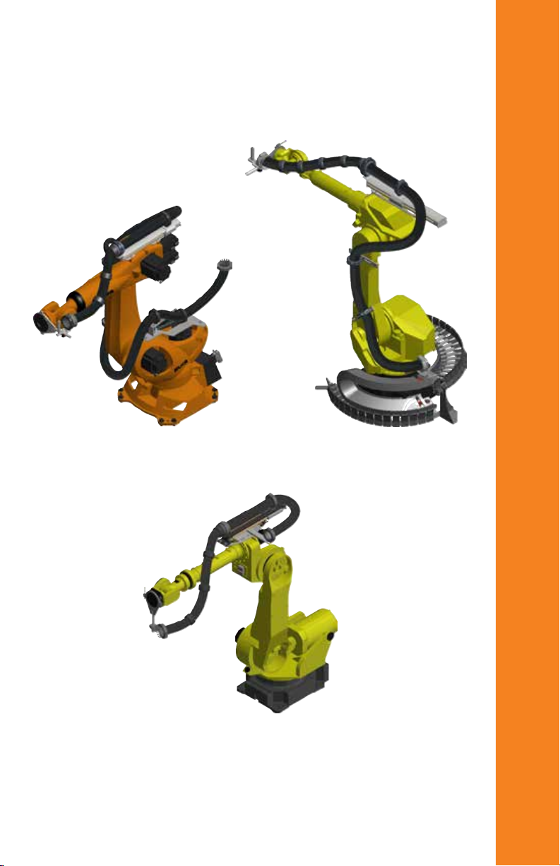
triflex®RSE linear
Installation examples
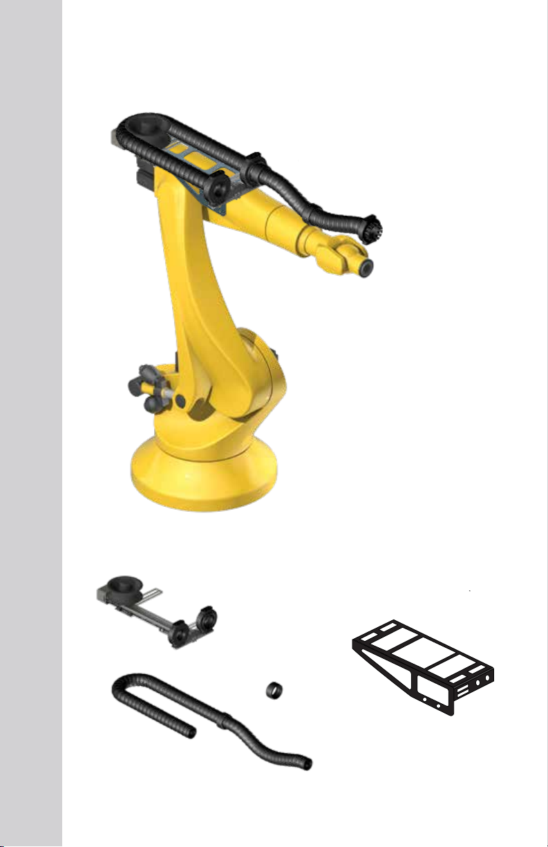
RSE Wheel installation guide
RSE Wheel retraction system
Mounting adapter
Note: Axis 3 mounting
adapters available for most
robot models
Protector
(Minimum 3 required)
14
Glide through bracket
must be on the same side
as the mounting feet
Adjustable
Adjustable
Configuring the retraction system
Mounting adapter installation example
Mounting adapter
15
Left hand system Right hand system
Easy to
adjust by
loosening
the bolts
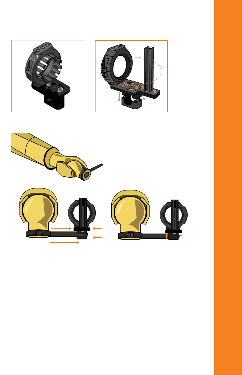
Note: RSE wheel bracket
arrangement can be modified
to opposite side if needed.
Remember to keep mounting
feet on the same side as the
glide-through bracket
Retraction system installation
Bolt mounting feet
to mounting adapter
Align the mounting
feet with the
mounting adapter
holes
Note: Tennis rackets available
for most robot models.
Tennis racket (axis 6 clamp) installation
Bolts need to
be tightened
uniformly
Note:
Can be mounted
in any direction
16
Axis 6 bracket installation
17
Tip: Install the bracket as close to the end of the handle as possible and tighten the
bolts equally.
Designed with
integrated
profile rail for
CFX clamp
Adjustable in four directions
Standard bracket Heavy duty bracket
Important: Ball end of
triflex®R at the EOAT
(End of arm tooling)
Tip: Make sure triflex®R is
not twisted
triflex®R installation
18
Install triflex®R in axis 6
mounting bracket first
triflex®TRE only - install locking
clips at each fixed bracket
position
Note: Easy cable installation
possible with triflex®TRE and
TRCF only. If using TRC,
cables will need to be fished
through individually

Installing CFX clamps to secure cables
1
2
3
4
5
1
2
3
4
5
1
2
3
4
5
Install protectors where triflex®R makes
contact with the robot
Tip: For quick release protectors, use a flat
head screwdriver to pry the two halves apart
1
2
3
4
5
Installing protectors
19
Protector:
To pretension the system, pull the triflex®forward two links
and install a protector at the exit of the moving end

20
triflex®RSE WHEEL
troubleshooting guide
Problem Solution
triflex®R breaks when RSE System is fully
extended
1. Install more triflex®R outside the RSE
System. The motion of the robot is
greater than the available travel of
the RSE System
RSE System does not function 1. Ensure the bands have tension
2. Confirm that the system is free of
debris
3. Reduce the length of the triflex®R
outside the RSE System
Carriage slams when the robot returns to
the hom position
1. Pull the system forward four links
and install a protector at the exit of
the pass-through bracket thereby
creating a stop
This manual suits for next models
4
Table of contents
Other igus Cables And Connectors manuals


