Ethan Allen 409501/409502 Owner's manual

Page 1
©2019 Ethan Allen Global, Inc.
DANGER
FIRE OR EXPLOSION HAZARD
If you smell gas:
• Shut off gas to the appliance.
• Extinguish any open flame.
• If odor continues, leave the area immediately.
• After leaving the area, call your gas supplier or fire department.
Failure to follow these instructions could result in fire or explosion,
which could cause property damage, personal injury, or death.
WARNING
Do not store or use gasoline, or other flammable vapors and liquids,
in the vicinity of this or any other appliance.
An LP cylinder not connected for use shall not be stored in the vicinity
of this or any other appliance.
WARNING: For Outdoor Use Only.
Installation and service must be performed by a
qualified installer, service agency, or the gas supplier.
WARNING
If the information in this manual is not followed exactly, a fire or explosion may
result, causing property damage, personal injury, or loss of life.
INSTALLER: Leave this manual with the appliance.
CONSUMER: Retain this manual for future reference.
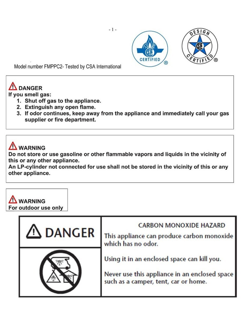
CARBON MONOXIDE HAZARD
• This appliance can produce carbon
monoxide, which has no odor.
• Using it in an enclosed space can kill you.
• Never use this appliance in an enclosed space
such as a camper, tent, car, or home.
DANGER
Fire Table Installation and Operation
409501/409502

TABLE OF CONTENTS
General Information ..............................................................................................................3
• Before Installation ....................................................................................................................3
• Parts List ....................................................................................................................................3
• Natural Gas & Propane Connections .....................................................................................3
Selecting the Location ........................................................................................................... 4
• For All Models ..........................................................................................................................4
• For LP Models ...........................................................................................................................4
• Required Clearances ...............................................................................................................5
Installing the Fire Table ........................................................................................................6
• Deck Insulation Kit ...................................................................................................................7
• Connecting the Fuel Supply: Important Information for Installers ....................................7
• Specifications for Fire Table and Fuel ...................................................................................7
• Installation Safety ..................................................................................................................... 8
• For Fire Tables that Connect to a Fuel Line ...........................................................................8
– Making the Connections ....................................................................................................8
• For Fire Tables that Connect to a Propane Cylinder ............................................................9
– Propane Cylinder: Safety Requirements ...........................................................................9
– Propane Cylinder Specifications ........................................................................................9
– Remote LP Tank System Enclosure Requirements (if applicable) ..................................9
– Securing the LP Tank to Prevent Tipping ........................................................................12
– Connecting the Cylinder ...................................................................................................12
Adding Lava Rock and Beach Stone.............................................................................13
Operating the Fire Table ....................................................................................................14
• Safe Operation .......................................................................................................................14
• Solid Fuels and Flammable Materials .................................................................................14
• If Fire Table Components are Wet .......................................................................................14
• Startup Procedures ................................................................................................................14
– For Fire Tables that Connect to a Fuel Line ....................................................................14
– For Fire Tables that Connect to a Propane Cylinder ......................................................15
• Shutoff Procedures ................................................................................................................15
• Emergency Shutoff ................................................................................................................15
Maintenance ............................................................................................................................16
• Service ....................................................................................................................................16
• Care .........................................................................................................................................17
• Replacement Parts .................................................................................................................17
Troubleshooting .....................................................................................................................18
Warranty Details .....................................................................................................................19

Page 3
GENERAL INFORMATION
CAUTION! FOR OUTDOOR USE ONLY.
GAS CONNECTIONS FOR NATURAL GAS AND PROPANE FIRE TABLES MUST BE
PERFORMED BY A LICENSED GAS TECHNICIAN AND COMPLY WITH YOUR LOCAL
BUILDING CODES. IMPROPER INSTALLATION, ADJUSTMENT, ALTERATION, SERVICE,
OR MAINTENANCE CAN CAUSE INJURY OR PROPERTY DAMAGE.
Fire tables are CSA certified to ANSI Z21.97-2014 and CSA 2.41-2014.
To qualify for warranty, instructions must be strictly followed. Warranty may be void if
not followed. Never alter product or configuration in any way.
BEFORE INSTALLATION
• Inspect fire table and its components for any damage before beginning installation.
• Fire tables must be handled with care. The most common source of damage is
mishandling of product before and during installation.
• Before beginning gas installation, ensure that the final location for the fire table is a flat,
level surface.
• Keep beach stone and lava rocks in bags until installation is complete.
• If table is to be installed on a deck made from wood, composite, or other combustible
materials, utilize the Deck Insulation Kit (see page 7).
PARTS LIST
1. Fire table with preassembled burner
2. Beach stones (4 bags)
3. Lava rock (1 bag)
4. Chrome key
5. 12' hose (if LP model)
6. Deck insulation kit
7. Basalt material (in Deck Insulation Kit)
8. 1" thick concrete pad (in Deck Insulation Kit)
NATURAL GAS & PROPANE CONNECTIONS
• Fire table ships preassembled; the re table encloses a burner assembly and a space
for beach stones and lava rock. Refer to page 6 for installation and operating instructions;
clearances to combustibles are shown on page 5.
• Each fire table has ventilation openings to comply with ventilation requirements. DO NOT
COVER OPENINGS.
• Ventilation openings may be used to accommodate a running gas line.
We recommend that our products be inspected before installation,
installed by, and serviced annually by qualified professionals who
are locally licensed by the authority having jurisdiction in gas piping.
• The installer and maintenance professionals must follow all instructions carefully to
ensure proper performance and safety.

Page 4
SELECTING THE LOCATION
Young children and animals should be carefully supervised
when they are in the area of fire table.
Both children and adults should be alerted to the hazards of high surface
temperatures and should stay away to avoid burns and clothing ignition.
Clothing or other flammable materials should not be placed
on or near fire table.
FOR ALL MODELS:
• All fire tables and systems are designed and intended for outdoor use only.
• Select a location that has good drainage and allows easy access for installation and
maintenance of the re table.
• Pick a location that allows sufcient horizontal room to enjoy the re table while allowing a
safe distance from the heat and ame.
• Select a location where the fire table can be attended during operation. Never leave an
operating fire table unattended or attended by someone not familiar with its operation or
emergency shutoff locations.
• If table is to be installed on a deck made from wood, composite, or other combustible
materials, utilize the Deck Insulation Kit (see page 7).
• Fire tables create very high temperatures; combustibles must be located far enough away
that there is no risk of ignition.
IMPORTANT: It is recommended that material such as granite, marble, or other dense stone
be kept away from heat and especially flame due to risk of cracking. Manufacturer is not
responsible for damage.
FOR LP MODELS:
• Do not position the propane cylinder inside the fire table. Choose a location where the tank
will be at least 54" away from the fire table as shown in figure 1 on page 5.
• Locate the tank and hose out of pathways to avoid accidental damage and prevent the hose
from becoming a trip hazard.

Page 5
REQUIRED CLEARANCES
The diagram illustrates required clearance between your fire table and nearby structures.
• All items may or may not apply to your project.
• Clearances apply to any and all sides of the project.
• Read and follow all instructions and local codes.
The fire table should be sited with a solid structure, building, or other combustible on no
more than two sides.
• For wall or ceiling screens, 50% free air space is recommended. Ethan Allen is not
responsible for screen that melts.
• For noncombustible screening, a 20" x 20" x .013" wire mesh thickness or one with more
open space is recommended.
• For all other noncombustible coverings, an on-site estimate of free air space will be necessary.
• The illustrated 84" minimum clearance above the fire table must be maintained over the
entire surface area of the burner.
Figure 1 – Clearances
Up to 200,000 BTU: Natural Gas OR Up to 100,000 BTU: LP Tank
For Outdoor Use Only
Residential or
commercial
building on
no more than
2 sides
Note: Deck installation – if installing fire table on a wood or
composite deck, it is required to use the Deck Insulation Kit.
Kit includes basalt material and instructions. See page 7.
Solid structure or
combustible on no
more than 2 sides –
12" minimum
clearance for
noncombustible
materials
Clearances:
Overhead solid structure:
(Roof, overhang, pergola or screen)
36"
84"
36"
Min.
54"
Fire Table Clearances Up to 200k BTU
Sides Surrounding Fire Table From Structure Or Combustibles 36"
Overhead Clearance Above Product 84"

Page 6
Gas supply line
Appliance connector flex line – connect
to gas supply line or hose for LP tank
Concrete pad
Basalt material (aluminum side up)
Burner
Installation surface
Fire Table Ventilation holes
(Do not block)
INSTALLING THE FIRE TABLE
WARNING
Failure to position the parts in accordance with these diagrams or failure to use only
parts specifically approved with this appliance may result in property damage or
personal injury. This applies to replacement components as well.
WARNING: FOR OUTDOOR USE ONLY
OPTION 1: FIXED
Appliance connector flex line
from key valve inlet to
permanent fuel supply
plumbed by certified installer
and inspected by local
authority.
Key valve inlet
Minimum 54"
Note: Ensure there are no gaps between basalt
material, installation surface, and gas line.
Concrete pad
Basalt material
(Aluminum side up)
Installation surface
Flex line
connections
must be above
basalt material
Basalt material
Installation
surface
Concrete
pad
OPTION 2:
REMOTE/PROPANE
CYLINDER
Appliance connector
flex line from key
valve inlet to 20 lb.
tank.
FIGURE 3: THE FIRE TABLE MAY BE FUELED BY A FIXED FUEL
SUPPLY (OPTION 1) OR A REMOTE PROPANE CYLINDER (OPTION 2)
FIGURE 2: FIRE TABLE COMPONENTS
WARNINGS
• Always ensure no gaps to prevent
any leakage onto installation surface.
• Do not recess fire pit below the
installation surface.
• Do not block any enclosure ventilation
holes.
• Always wear gloves and protective
eyewear.

Page 7
DECK INSULATION KIT
Install deck insulation as shown if fire table is to be installed on a combustible surface.
1. Install concrete pad (see figure 2).
2. With the aluminum side UP, insert the basalt material over the supply line. Push the basalt
material all the way down until it rests on top of the concrete pad. See figures 3 and 4.
3. IMPORTANT: Check to ensure there are no gaps around the supply line. See figures 3 and 4.
ALWAYS ENSURE THE DECKING MATERIAL WILL SUPPORT THE ADDITIONAL WEIGHT OF
THE FIRE TABLE.
CONNECTING THE FUEL SUPPLY: IMPORTANT INFORMATION FOR INSTALLERS
It is the responsibility of the installer to conform with
• Local codes
• The National Fuel Gas Code, ANSI Z223.1/NFPA 54 or International Fuel Gas Code
• Natural Gas and Propane Installation Code, CSA B149.1, Propane Storage and Handling
Code, CSA B149.2
IMPORTANT: It is the installer’s responsibility to ensure a safe installation and to educate the
end user as to proper operation. Leave this manual with the end user.
• Please carefully follow the instructions in this manual to prevent personal injury or property
loss. These instructions contain information critical to the safe installation and operation of
the fire table.
• Instructions may be updated periodically. It is the installer’s responsibility to contact
Ethan Allen Client Services (888.324.3571) for applicable updates.
SPECIFICATIONS FOR FIRE TABLE AND FUEL
Only use fuel type specified for this fire table (refer to the product label on the bottom of the
burner). Never use an alternative fuel such as biofuel, ethanol, lighter fluid, or any other fuel. Gas
pressure and type should be checked prior to use and installation by a licensed gas technician.
• Natural Gas Fire Table – Supply pressure: Minimum: 3.5" W.C.; Maximum: 7.0" W.C.
• LP Gas – Supply pressure: Minimum: 8.0" W.C.; Maximum: 11.0" W.C.
IMPORTANT: Ensure any flex line that may be used from the permanent main fuel supply to
the product is rated to the stated max BTU of the product and certified to install ANSI Z21.75/
CSA 6.27. Refer to the product label on the bottom of the burner for the maximum BTU specifications.
Figure 4
Basalt-
Aluminum
Side Up

Page 8
INSTALLATION SAFETY
• To prevent damage, unhook the fire table from the gas supply for pressure leak tests.
• Burn testing: It is the responsibility of the qualified installer to test for gas leaks at all
connections.
• Gas plumbing connections: Use only joint compound or tape that is resistant to all gases.
Apply joint compound to all male pipe fittings only – DO NOT use on flex line flared fittings.
Be sure to tighten every joint securely.
• Perform all leak tests with leak detector or leak reactant. Do not smoke or permit sources
of ignition to enter the area when conducting a leak test.
FOR FIRE TABLES THAT CONNECT TO A FUEL LINE
We recommend that our tables be installed by professionals who are locally licensed by
the authority having jurisdiction in gas piping.
Fire table must have a gas shutoff on the outside of the exterior of the fire pit to allow for
emergency shutoff and maintenance. The gas shutoff should not be used to adjust
flame height.
The installer is responsible for using the correct fuel line sizing that is able to supply the
stated maximum BTU for the product — refer to product label on the bottom of the burner
for specifications.
MAKING THE CONNECTIONS
1. Position fire table safely with access to all gas connections for testing.
2. Shut off gas supply valve on the line to be connected to fire table.
3. Connect fire table to main gas supply. To prevent whistling, ensure the appliance connector
flex line is smooth and doesn’t have any kinks or sharp turns.
4. Turn on gas supply, purge gas lines of air, and perform leak test on all inlet connections.
Repair as needed.
5. Light fire table using startup procedures on page 14. It may take several cycles to purge
air from the lines.
6. Turn off fire table and allow cooling.
7. Apply lava rock and beach stone as described on page 13. When filling the burner pan
with lava rock, the instructions on page 13 must be followed.
8. Verify correct operation and lighting. Typical flame height is 10" to 12".
9. Review safety manual with end user and instruct not to change/modify fire table or media.
Review service valve location for emergency shutdown with end user.
10. Leave manual with end user.

Page 9
FOR FIRE TABLES THAT CONNECT TO A PROPANE CYLINDER
We recommend that our products be installed by professionals who are locally licensed
by the authority having jurisdiction in gas piping.
PROPANE CYLINDER: SAFETY REQUIREMENTS
• This appliance has been designed for use with a single 20 lb. or 30 lb. propane cylinder
(not supplied). One cylinder should be used at a time.
• The propane cylinder should be checked by your propane supplier prior to installation
and use.
• Never use a cylinder with a damaged valve. A worn cylinder may be hazardous and should
be checked by your propane supplier.
• Use only a propane supply cylinder constructed and marked in accordance with the U.S.
Department of Transportation (D.O.T.) Specications for LP Gas Cylinders, or the Standard
for Cylinders, Spheres, and Tubes for Transportation of Dangerous Goods and Commission,
CAN/CSA-B339.
• Do not store a spare LP gas cylinder under or near this appliance.
• Never fill the cylinder beyond 80% full.
• Only use the pressure regulator and hose assembly provided with this appliance or
replacement pressure regulators and hose assemblies as specified by the manufacturer.
The regulator supplies a pressure of 11" water column to the appliance and has a QCC1
type fitting.
PROPANE CYLINDER SPECIFICATIONS
• The propane cylinder must be provided with a cylinder connection device compatible with
the connection for outdoor appliances.
• The propane cylinder must be supplied with a shutoff valve terminating in a propane
cylinder valve type QCC1 and include a collar to protect the cylinder valve. A QCC1 cylinder
has a positive seating connection, which will not allow gas to flow until a positive seal has
been achieved. It is also equipped with an excess flow device. In order to attain full flow to
the appliance, the valve must be in the off position when the cylinder valve is turned on.
• The propane cylinder must have a safety relief device having direct communication with the
vapor space of the cylinder.
• The cylinder supply system must be arranged for vapor withdrawal.
• The cylinder shall incorporate a listed overfill protection device (OPD).
REMOTE LP TANK SYSTEM ENCLOSURE REQUIREMENTS (IF APPLICABLE)
An LP tank may be covered and shielded from sight with the use of an enclosure. A 20 lb.
cylinder enclosure which meets the requirements of this section is available from Ethan Allen
as item number 409503. It is still the responsibility of the installer to ensure that all enclosures
meet local code requirements.
For an enclosure not purchased from Ethan Allen, follow these recommended specifications.
You must also follow local codes.

Page 10
5" max
5" max
1" max
2" min
Top opening
Bottom opening
Figure 5 – Top and bottom side ventilation openings for LP tank enclosure
IMPORTANT: Locate the LP tank and enclosure out of pathways to avoid accidental
damage and prevent it from becoming a trip hazard.
IMPORTANT: The tank enclosure should be a minimum of 54" from the fire pit.
• One side of the enclosure shall be completely open; OR
• For an enclosure having four sides, a top, and a bottom:
– At least two ventilation openings shall be provided in the side walls of the enclosure,
located within 5" (127 mm) of the top of the enclosure, equally sized, spaced at a minimum
of 180 degrees, and unobstructed. The opening(s) shall have a total free area of not less
than 1 square inch per pound (14.2 cm2/kg) of stored fuel capacity. See figure 5 below.
– Ventilation opening(s) shall be provided at the floor level of the enclosure and shall
have a total free area of not less than 1/2 square inch per pound (7.1 cm2/kg) of stored fuel
capacity. If ventilation openings at floor level are in a side wall, there shall be at least two
openings. The bottom of the openings shall be 1" (25.4 mm) or less from the floor level
and the upper edge no more than 5" (127 mm) above the floor level. The openings shall be
equally sized, spaced at a minimum of 180 degrees and unobstructed. See figure 5 below.
– Every opening shall have minimum dimensions so as to permit the entrance of a 1/8" (3.2 mm)
diameter rod.
Ventilation openings in sidewalls shall not communicate directly with other enclosures of the
appliance. See tables A and B.
Table A: LP Tank Enclosure Opening Specifications
LP Tank Size Top Opening Bottom Opening
20 lb. (9.1 kg) 20 in2(130 cm2) 10 in2(65 cm2)
30 lb. (13.6 kg) 30 in2(195 cm2) 15 in2(100 cm2)

Page 11
Minimum
54"
Figure 6
Table B: LP Tank Enclosure Opening Specifications
2 openings for each top and bottom – 180° apart
From LP tank base to bottom of opening – Max. 1" (25.4 mm)
From oor to base of LP tank – Min. 2" (50.8 mm)
The cylinder valve shall be readily accessible for hand operation. A door on the enclosure to
gain access to the cylinder valves is acceptable, provided it is nonlocking and can be opened
without the use of tools. Designs using a cover to gain access to the cylinder and cylinder
valve shall be provided with handles or the equivalent at a minimum of 180 degrees apart to
facilitate lifting of the cover.
The enclosure for the LP gas cylinder shall isolate the cylinder from the re table to provide
• shielding from radiation;
• a ame barrier; and
• protection from foreign material.
There shall be a minimum clearance of 2" (50.8 mm) between the oor of the nondisposable
LP gas cylinder enclosure and the ground.
The design of the enclosure shall be such that
• nondisposable LP gas cylinder can be connected, disconnected, and the connections
inspected and tested outside the cylinder enclosure; and
• those connections, which could be disturbed when installing the cylinder in the
enclosure, can be leak-tested inside the enclosure.
WARNING
Always ensure LP tank is secure and prevented from tipping.
WARNING
• Locate the LP tank and enclosure out of pathways to avoid accidental damage and
prevent them from becoming a trip hazard.
• Locate the hose out of pathways to avoid accidental damage and prevent it from
becoming a trip hazard.
WARNING
Failure to follow location and mounting guidelines for the LP tank could result in
serious injury.
Loading the LP tank:

Page 12
SECURING THE LP TANK TO PREVENT TIPOVER
1. Select a at, level location for the propane tank following the guidelines adjacent to
gure 6.
2. If using the Ethan Allen propane cylinder enclosure, a 20 lb. propane cylinder properly
installed inside of the enclosure is secured from tipover without the use of a bracket.
3. If using a different propane cylinder enclosure design, or if using a 30 lb. propane tank,
follow these guidelines to prevent the cylinders from tipping over.
a. Fasten an L-bracket to the bottom of the propane tank using a nut and bolt
(not supplied). Ensure the nut is tight and will not loosen.
b. Screw the bracket to the mounting surface. For concrete surface, use a concrete
anchor (not supplied). Ensure that screw is tight so that the cylinder cannot move.
CONNECTING THE CYLINDER
1. Visually inspect hose before installation. Replace hose prior to putting the appliance
into operation if there is any evidence of excessive abrasion, wear, holes, pinholes, tears,
or other damage.
2. Ensure the appliance connector ex line and hose are both smooth and have no kinks or
sharp turns.
3. Remove the cap or plug from the cylinder fuel valve.
4. Insert the black QCC1 regulator nipple onto the QCC1 fuel valve and tighten until snug.
Do not use tools.
5. Leak test all joints prior to using the gas appliance. Repair as needed. Additional leak tests
must be performed annually and each time a cylinder is hooked up or if a part of the gas
system is replaced.
6. Light re table using startup procedures on page 15. It may take several cycles to purge
air from the lines.
7. Turn off re table and allow cooling.
8. Apply lava rock and beach stone as described on page 13. When lling the burner pan
with lava rock, the instructions on page 13 must be followed.
9. Verify correct operation and lighting. Typical ame height is 10" to 12".
10. Review safety manual with end user and instruct not to change or modify re table or media.
11. Leave manual with end user.

Page 13
ADDING LAVA ROCK AND BEACH STONE
CAUTION!
• Please note that lava rock and beach stone are both 100% natural products and occasional
cracking and/or popping may occur when heated.
• It is highly recommended to inspect and discard all stones with hairline cracks before
placing around the gas burner.
• When using your re table for the rst time, it is recommended to operate the burner for at
least 1 to 2 hours while keeping a safe distance in the rare occurrence that breakage or
popping occur.
• Please note that using a protective weather cover may also help avoid breakage as stone
can pop or crack when wet. Protective covers are available from Ethan Allen (item number
409501CVR for rectangular re tables and 409502CVR for square re tables).
INSTRUCTIONS
1. Place lava rock on the burner surface. Apply it ONLY deep enough to cover the burner
pan; do not exceed the height of the burner tube.
2. Fill the re table enclosure with beach stone, distributing it over the entire surface area.
The total combined depth of the lava rock and beach stone should be 1/4" to 1/2"
above the burner.
3. Ensure that none of the stones block the burner holes/gas openings.
IMPORTANT
• Never install a mesh or screen under the media.
• Media affects ame pattern greatly. It is possible to create an unusual ame pattern that
could damage your enclosure. Enclosure damage from an open ame re feature is not
covered under any warranty.
• The re table is designed to use the supplied media correctly installed over the burner
to achieve proper combustion. Use of other types of media can result in safety hazards
and damage to the re table.
• Never use any material that is nonporous and holds moisture, such as gravels, pebbles,
river rock, etc. This material, when heated, will cause the trapped moisture to boil, and the
material may fracture unexpectedly. This material is not sufciently porous to allow heated
steam to readily escape; it can break and cause personal injury or damage.
• When using a table cover, ensure table, stones, and burner are completely cool. Hot
stones or burners will damage the cover.
• The use of concrete logs is not recommended.

Page 14
OPERATING THE FIRE TABLE
Failure to follow these instructions could result in re or explosion, which could cause property
damage, personal injury, or death.
SAFE OPERATION
STOP! Read the safety information on "What to do if you smell gas." See page 1.
• Before use, conrm that your gas technician has tested all gas connections for leaks. Do not
use re table if there is any evidence of leaking gas. If suspicious of leaking gas, turn off the
main gas supply and repair immediately.
• Always ensure that the re table is supervised by a responsible adult familiar with emergency
shutdown procedures.
• Young children and animals should be carefully supervised when they are in the area of the
re pit.
• Do not use the re table as a seating area. Wind and gusty conditions will affect the ame in
an unpredictable manner. If conditions exist that are not safe, turn off the re table.
• When the re table is not in operation, turn off the chrome key gas valve. See gure 8.
SOLID FUELS AND FLAMMABLE MATERIALS
• Solid fuels shall not be burned in the re table. Leaves, sticks, wood, paper, clothing, food
material, etc. should be kept away from the re table.
• Conrm there is no vegetation or debris in the re table that could interfere with safe
operation, including water.
• Combustible materials, gasoline, and other ammable vapors and liquids should not be
placed on or near the re table.
• Do not use the re table for cooking. Do not heat unopened glass or metal containers of
food in the re table; internal pressure in these vessels may build up and cause them to
burst, potentially causing personal injury or damage.
IF FIRE TABLE COMPONENTS ARE WET
• Do not use this appliance if any part has been under water. Immediately call a qualied
service technician to inspect the appliance and to replace any part of the control system
and any gas control that has been under water.
• If lava rock and/or beach stones are wet, allow re table to burn for 45 minutes prior to
coming within 15 feet of the re table.
STARTUP PROCEDURES
FOR FIRE TABLES THAT CONNECT TO A FUEL LINE
1. Slowly turn ON the re table’s gas valve by inserting chrome key into
the chrome key hole and turning it counterclockwise. See gure 7.
2. Keeping one hand on the chrome key, use the other hand to place
a long-handled lighter or lit match over the center of the re table.
ON
Figure 7

Page 15
3. After the burner lights, remove lighter or match. NOTE: If burner does not light, turn
chrome key valve off and allow gas to clear. Then, repeat steps 1–3.
4. Turn the chrome key to adjust ame to desired height.
5. Remove chrome key after use and store in a safe place, out of reach of children.
FOR FIRE TABLES THAT CONNECT TO A PROPANE CYLINDER
1. Visually inspect the hose before each use of the re table. Replace hose prior to operation if
there is any evidence of excessive abrasion, wear, holes, pinholes, tears, or other damage.
2. Visually inspect the hose’s routing before each use of the re table. Ensure that the hose is
smooth with no kinks or knots, and that it is safely routed through an area where it does not
pose a trip hazard.
3. Ensure that the re table’s gas valve is turned OFF by inserting the chrome key into the
chrome key hole and turning it clockwise. See gure 8.
4. Slowly open the gas valve on the LP tank.
5. Slowly turn ON the re table’s gas valve by inserting chrome key into the chrome key hole
and turning it counterclockwise. See gure 7.
6. Keeping one hand on the chrome key, use the other hand to place a long-handled lighter
or lit match over the center of the re table.
7. After the burner lights, remove lighter or match. NOTE: If burner does not light, turn
chrome key valve off and allow gas to clear. Then, repeat steps 5–7.
8. Turn the chrome key to adjust ame to desired height.
9. Remove chrome key after use and store in a safe place, out of reach of children.
SHUTOFF PROCEDURES
1. Turn OFF gas valve by inserting the included chrome key into the
chrome key hole and turning it clockwise. See gure 8.
2. Once the burner and aggregate have completely cooled, use appropriate
cover to protect re table. Please note that using a protective weather
cover may also help avoid breakage, as stone can pop or crack when wet.
Protective covers are available from Ethan Allen (item number 409501CVR
for rectangular re tables and 409502CVR for square re tables).
3. Remove chrome key after use and store in a safe place, out of reach of children.
EMERGENCY SHUTOFF
1. In an emergency, stop the ow of gas to the burner.
a. In xed fuel system, turn off the gas at the chrome key valve and the service valve,
starting with whichever is closest.
b. In a propane cylinder system, turn off the gas at the chrome key valve or the propane
cylinder, starting with whichever is closest.
2. Extinguish any open ame.
3. If gas odor continues, leave the area immediately.
4. After leaving the area, call your gas supplier or re department.
OFF
Figure 8

Page 16
MAINTENANCE
Any guard, barrier, or other protective device removed for servicing
the appliance shall be replaced prior to operating the appliance.
It is imperative that the control compartment, burners, and circulating air
passageways of the fire table are kept clean.
More frequent cleaning may be required as necessary.
In the U.S., we recommend that our products are serviced by a professional certified by
the National Fireplace Institute (NFI) as an NFI Gas Specialist.
SERVICE
• Ensure gas is shut off and fire table is cool before servicing.
• Burner cleaning and inspection (once per year): If flames exhibit any abnormal shapes or
behavior, or if burner fails to ignite properly, then the burner holes may require cleaning. The
appliance can be cleaned by carefully removing the media to allow access to burner. Use a
brush to carefully remove dust, spider webs, and loose particles from base, and burner itself.
If evidence of damage, burner must be replaced with burner specified by manufacturer.
• Yearly inspection by a qualified service technician of the natural gas orifice or LP air
mixer orifice is required to ensure your fire feature performs properly.
– Clean and visually inspect natural gas orifice for any damage or abnormalities.
– Clean and visually inspect propane orifice for any damage or
abnormalities. In some areas of the country, spiders or insects
have been known to build nests and or lay eggs in the air intake
holes of the air mixer orifice for LP units. This can cause fuel to
fill the fire feature cavity and result in personal injury or property
damage. Remove the fine mesh spider guard which is covering
the air intake holes, clean and inspect the holes, and then reinstall
the mesh spider guard before returning the air mixer orifice to use.
(Figure 9 shows LP air mixer orifice with mesh spider guard removed.)
– Beach stone crack inspection (once per year): It is recommended that beach stones are
reinspected for hairline fractures once per year, at the start of the season of use. Discard
stones with hairline cracks, and contact Ethan Allen Client Services (888.324.3571) if you
need to request replacement stones. Broken stones without hairline cracks do not need to
be discarded for safety reasons, but they are often removed to maintain visual continuity.
Figure 9
Air Intake
Gas
Out
Gas
In

Page 17
CARE
• Always ensure that your fire table is draining water properly and drainage/ventilation
openings are not obstructed by debris.
• Keep fire table covered at all times when not in use, and keep it free of debris. Use of a
cover will protect the fire table and prolong burner life.
• Concrete can be cleaned with a mild soap and water solution. Never use abrasives or strong
chemicals as they may stain the surface. A spill should be cleaned immediately by carefully
blotting the spill with a paper towel or clean white towel. Do not wipe a spill as it may force
the potential stain deeper into the surface. If the stain persists, contact Ethan Allen Client
Services (888.324.3571) for further instructions.
• Hairline cracks may occur in your concrete product. This is a natural characteristic of
concrete, and not cause for alarm. Fire tables are fiber reinforced so cracks do not have
the potential to grow or separate.
REPLACEMENT PARTS
Please contact Ethan Allen Client Services (888.324.3571) for replacement parts. The following
replacement parts are available:
• Beach stone
• Lava rock
• Chrome key
• Pressure regulator and hose assembly
Other replacement components may be available upon request.
NOTE: If replacement beach stone and lava rock media are required, contact Ethan Allen
Client Services. DO NOT USE UNTREATED AGGREGATE.

Page 18
TROUBLESHOOTING
Below, we've listed some potential problems you may encounter, their possible causes, and
potential solutions. Please contact a local certied technician for service and repair.
Problem Possible Causes Solution
Burner will not light Air in gas line Bleed air from gas line by slowly
opening valve
Propane (LP) – check gas level in
tank
No gas ow – gas not ON or
line obstruction
Conrm gas is ON upstream
Possible debris in line – insulation,
dirt, plastic, etc.
Burner will not stay lit Gas pressure improper Conrm proper gas pressure
(see page 7)
Burner obstructed Conrm no water or debris in burner
Improperly applied or too
much media
Reapply media (see page 13)
Too windy Use when less windy
Low ame when
turned to High
Gas pressure improper Conrm proper gas pressure
(see page 7)
Propane (LP) – Improper
lighting procedure
Fire table valve must be OFF when
tank is turned ON. Turn tank
ON slowly to allow pressure to
equalize, then turn ON re pit
Lack of gas Check gas level of LP tank
Supply hose is pinched Reposition supply hose as
necessary
Natural Gas (NG) –
undersized gas supply line
Gas pipe, ex line, shutoff valve,
etc. must be sized to deliver re
table input pressure and BTU
requirement
Flame is creating large
amount of soot
Propane (LP) – mesh spider
guard or venturis are blocked
with debris – grass, dirt, etc.
Thoroughly clean spider guard
(see page 16)
Noise when lit Whistling – ex line bent
too sharp
Reroute ex line to reduce bend
Propane (LP) – humming
regulator
Not a defect – normal occurrence
on hot days due to internal
vibrations in regulator

Page 19
WARRANTY DETAILS
LIMITED MANUFACTURERS WARRANTY
STAINLESS STEEL COMPONENTS (residential use) 5-YEAR LIMITED WARRANTY
STAINLESS STEEL COMPONENTS (commercial use) 1-YEAR LIMITED WARRANTY
CONCRETE SHELL 1-YEAR LIMITED WARRANTY
This warranty does not apply to, and the manufacturer assumes no responsibility for, damage
or defect due to any one of the following:
• Improper handling, maintenance, or installation of product
• Modication or alteration to the product in any manner which increases its susceptibility to
damage
• Any case where the product has been misused, intentionally damaged, or damaged as a
result of negligence
Table of contents
Popular Outdoor Fireplace manuals by other brands

Outdoor GreatRoom Company
Outdoor GreatRoom Company Vaughn VGHN-GR-K installation instructions

Firegear
Firegear FPB-G16RBSMT-N Installation and operating instructions
Paloform
Paloform Robata 72 concrete Installation & owner's manual
Barbara Jean
Barbara Jean OB24MVN manual

Landmann
Landmann Heatwave 28051 Assembly and use instructions
Sunnydaze Decor
Sunnydaze Decor NB-501 manual


