2
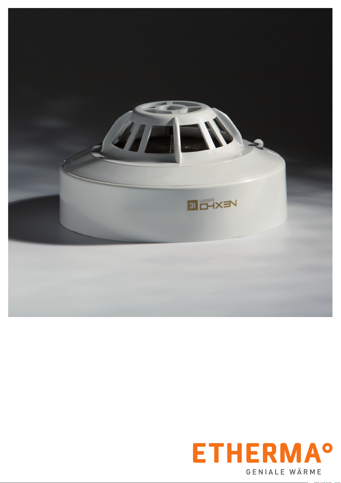
MONTAGE- UND GEBRAUCHSANLEITUNG | eNEXHO-IC - FEUERMELDER
Mit Ihrer Wahl für ETHERMA haben Sie sich für eine geniale
Wärmelösung entschieden. Wir danken für Ihr Vertrauen. In
uns haben Sie einen kompetenten Partner mit mehr als 30
Jahren Erfahrung. ETHERMA setzt auf ständige Innovation,
höchste Produktqualität und modernes Design.
Wir unterstützen Sie mit umfangreichen Serviceleistungen und
nden die individuell passende Produktlösung für Sie.
Die folgende Anleitung soll Ihnen helfen, Ihr ETHERMA Qua-
litätsprodukt so wirkungsvoll wie möglich einzusetzen. Sie
gibt wichtige Hinweise für die Sicherheit, die Installation, den
Gebrauch und die Wartung der Geräte. Bitte lesen Sie die in
dieser Anleitung aufgeführten Informationen daher sorgfältig
durch und behalten Sie sie für Rückfragen zu einem späteren
Zeitpunkt auf.
Der Hersteller haftet nicht, wenn die nachstehenden Anwei-
sungen nicht beachtet werden. Die Geräte dürfen nicht miss-
bräuchlich, d.h. entgegen der vorgesehenen Verwendung, be-
nutzt werden.
Die Verpackung Ihres hochwertigen ETHERMA Produktes be-
steht aus recycelbaren Werkstoffen.
EINLEITUNG
TECHNISCHE DATEN
Verbrauch im Ruhezustand: ................................P <0,5 mW
Verbrauch im Alarmzustand:................................P <0,6 mW
Funkfrequenz:............................................f = 868 MHz
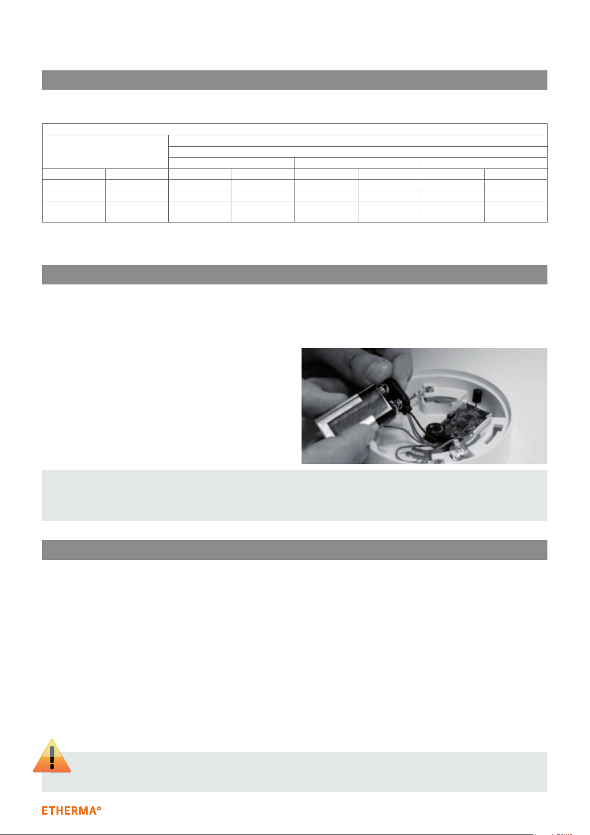
Interne Stromversorgung: ..................................9-Volt-Batterie
Externe Stromversorgung: .................................12 V (Gleichstrom)
Tastkopf: ................................................Typ A2S
Magnettest | Doppelte Alarm-LED | Impuls-LED
Dieses System wurde sorgfältig entwickelt, um so effektiv
wie möglich zu arbeiten. Dennoch kann es unter Umständen
den Schutz versagen. Es ist möglich, dass Alarmsysteme um-
gangen werden oder dass sie aus einem anderen Grund nicht
funktionieren, u. a.:
› Ein Sicherheitssystem muss korrekt installiert sein, um an-
gemessenen Schutz zu ermöglichen. Das Gerät sollte auch
nicht an Orten installiert werden, wo es Feuchtigkeit oder
Spritzwasser ausgesetzt ist. Jede Installation sollte noch
einmal kontrolliert werden, um sicherzustellen, dass alle
Überwachungsbereiche hinreichend abgedeckt sind.
› Es ist sehr wichtig, dass das Sicherheitssystem regelmä-
ßig gewartet wird. Auf diese Weise kann sichergestellt wer-
den, dass es leistungsfähig bleibt und Teile ggf. aktualisiert
oder ersetzt werden, wenn sie nicht mehr den gewünschten
Schutz gewährleisten.
› Fehler in der Stromzufuhr. Der eNEXHO-IC-Feuermelder
benötigt für den problemlosen Betrieb eine passende Span-
nungsversorgung. Bei Batteriebetrieb kann es sein, dass die
Batterien nicht ordnungsgemäß arbeiten. Selbst, wenn die
Batterien korrekt funktionieren, müssen sie dennoch in gu-
tem Zustand und richtig eingelegt sein. Im Falle einer exter-
nen Spannungsversorgung führt jede noch so kurze Span-
nungsunterbrechung zum Funktionsausfall des Gerätes.
› Die Lebensdauer einer Batterie hängt von ihrer Umgebung
und der Anzahl der Betriebsstunden ab. Umweltbedingun-
gen wie übermäßige Feuchtigkeit, hohe oder niedrige Tem-
peraturen oder plötzliche Temperaturschwankungen kön-
nen die Lebensdauer einer Batterie verkürzen. Kontrollen
und regelmäßige Wartung halten das System in einem guten
Betriebszustand.
› Geräte mit Alarmton könnten von Personen mit Hörproble-
men nicht wahrgenommen werden.
› Die Telefonleitung kann gestört oder zeitweilig besetzt sein.
Ein Einbrecher könnte sie auch mit noch rafnierteren Mit-
teln blockieren. Diese wären nur sehr schwer festzustellen.
› Unter gewissen Umständen ist es möglich, dass Schaden
an Bewohnern oder Eigentum entsteht, obwohl das System
korrekt funktioniert, weil nicht rechtzeitig auf den Alarm re-
agiert werden kann.
› Obwohl alles dafür getan wurde, das System so zuverlässig
wie möglich zu machen, kann es durch einen Fehler in einem
Bauteil zu einem Versagen kommen.
› Die meisten Probleme, durch welche Alarmsysteme ver-
sagen, können durch Kontrollen und regelmäßige Wartung
festgestellt werden. Das ganze System sollte wöchentlich
bzw. sofort nach einem Einbruch, einem Einbruchsversuch,
einem Brand, einem Unwetter, Erdbeben, Unfall oder jeder
Art von Bautätigkeit überprüft werden.
› Trotz seiner Efzienz ist ein Alarmsystem kein Ersatz für
eine Hausrats- oder Lebensversicherung. Ein Alarmsystem
befreit auch nicht davon, Vorsichtsmaßnahmen zur Vermei-
dung oder Minimierung von Schäden in einer Notfallsituation
zu ergreifen.
WARNUNG