TECHNICAL SPECIFICATIONS / ТЕХНИЧЕСКИ ХАРАКТЕРИСТИКИ
General Description
SensoMAG MRB50 is a manual call point for emergency start, or forced
activation of the extinguishing process on the protected area.
The call point is designed to work with extinguishing fire control panels and it
is suitable for surface indoor mounting. The pressing of the resettable
(flexible) operating element provides immediate activation of the
extinguishing process on the protected area.
SensoMAG MRB50 is equipped with a transparent protective cover which
helps for minimizing the unwanted activation of the call point.
SensoMAG MRB50 is connected to the “MANUAL RELEASE” input of the
extinguishing panel according the connection diagram presented on page 2
of this installation instruction manual.
Working Principle
In case of a fire alarm in the protected site, the user can manually start the
extinguishing process skipping the preset time for delay of the extinguishing,
if it is already started. The user must lift up the protective cover and to press
the operation element in the middle (the circle). The operating element will
move down (a click is heard). This will activate the “MANUAL RELEASE”
input of the extinguishing panel and to trigger the extinguishing process on
the area.
The resetting of the flexible element back in stand-by mode is done with the
special key tool - fix the long side of the tool in the opening in the front cover
bottom and push up until the flexible element moves up in middle position (a
click is heard).
Testing the Call Point Operation
To test the manual release button, first switch on to “DISABLED” operation
mode of the extinguishing panel. Then press the operation element on the
middle until it moves down (a click is heard). The manual release button
operates correctly if the “ACTIVATED” LED on the front panel of the
extinguishing panel is lighting on in yellow, meaning the MANUAL RELEASE
input on the main PCB has been activated.
To return to normal operation mode of the extinguishing system, reset the
manual release button as described above; then reset the control panel and
at the end, switch on to “AUTOMATIC” or “MANUAL” operation mode.
Maintenance and Service
The manufacturer recommends the call point to be inspected for visible
physical damages every week. Test the call point operation as a part of the
whole extinguishing system according the local regulations in the country.
In case of damage of the protective transparent cover, it can be easily
replaced with a new one.
English Installation Instructions
Общо описание
SensoMAG MRB50 е ръчен бутон, предназначен за аварийно стартиране или
моментално задействане на процес по пожарогасене на охранявания обект.
Бутонът е проектиран за работа с контролни панели за пожарогасене и е
подходящ за стенен повърхностен монтаж в закрити помещения. С натискане на
гъвкавия работен елемент се осигурява моментално задействане на
пожарогасенето на обекта.
SensoMAG MRB50 е с фабрично монтиран предпазен прозрачен капак,
осигуряващ защита срещу неволно или нежелано задействане на бутона.
SensoMAG MRB50 се свързва към вход “MANUAL RELEASE” (Ръчно задействане)
на пожарогасителния панел според дадената диаграма на свързване на стр. 2 на
тази инструкция за инсталиране.
Принцип на действие
В случай на пожарна аларма в охранявания обект, потребителят може ръчно да
стартира процеса на пожарогасене, като по този начин се прекратява и
предварително настроеното време за забавяне на пожарогасенето, ако вече е
стартирало. Потребителят трябва да повдигне капака на бутона и да натисне
работния елемент в средата (в кръга). Работният елемент ще се измести надолу
(чува се изщракване). Това ще задейства вход “MANUAL RELEASE” на платката
на пожарогасителния контролен панел, който ще активира процеса на
пожарогасене незабавно.
Възстановяване на ръчния бутон в дежурен режим се извършва с помощта на
специализиран инструмент (ключ) - дългата му част се поставя в отвора от
долната страна на предния капак и се натиска нагоре докато работният елемент
се върне в средно (неутрално) положение (чува се изщракване).
Тестване за работоспособност
За да тествате работата на ръчния бутон, първо превключете контролния панел в
работен режим “ЗАБРАНЕН”. Натиснете работния елемент на бутона в средата,
докато не се измести надолу (чува се изщракване). Бутонът за аварийно
стартиране на пожарогасене работи коректно, ако при задействането му светва
постоянно светодиод “АКТИВИРАНЕ” на предния панел на пожарогасителния
панел, което означава, че е активиран вход “MANUAL RELEASE” на основната
платка.
За връщане към нормален работен режим на пожарогасителната система,
ресетирайте бутона както е описано по-горе; след това ресетирайте контролния
панел и накрая превключете към “АВТОМАТИЧЕН” или “РЪЧЕН” работен режим.
Поддръжка и сервиз
Производителят съветва да се извършва ежеседмичен оглед за видими
механични повреди на ръчния бутон за аварийно спиране. Тествайте неговата
работоспособност като част от цялата система за пожарогасене в съответствие с
прилаганите наредби и изисквания на регионално и местно ниво.
В случай на счупване на защитния предпазен капак той може лесно да се замени
с нов.
Български Инструкция за инсталиране
Indoor Use /
Вътрешен
монтаж
18020894; RevA; 02/2017
SensoMAG MRB50
Manual release call point
Teletek Electronics JSC
Address: 14A Srebarna Str,
1407 Sofia, Bulgaria
EN 54-11
EN 12094-3
Type B
DoP No: 115
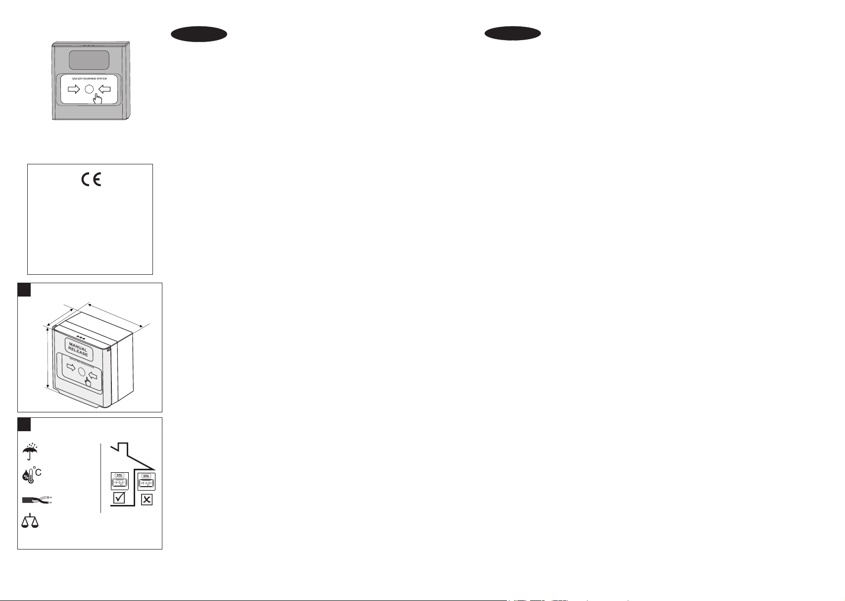
94mm
92mm
60mm
Dimensions / Размери
!
IP40
~169g
Installation / Instalación /
Инсталиране
!
Operating voltage . . . . . . . . . . . . . . . . . . . . . . Работно напрежение . . . . . . . . . . . . . 9÷30VDC
Switch . . . . . . . . . . . . . . . . . . . . . . . . . . . . . . . Превключвател. . . . . . . . . . . . . . . . . . NO type (normally open/тип NO (нормално отворен)
Material (plastic), color . . . . . . . . . . . . . . . . . . Материал (пластмаса), цвят . . . . . . . ABS, yellow/жълт
Type of the frangible element . . . . . . . . . . . . . Тип на работния елемент . . . . . . . . . Resettable/възстановяем
Dimensions (without protective cover) . . . . . . Размери (без предпазен капак). . . . . 90x90x56mm
Dimensions (with protective cover) . . . . . . . . . Размери (с предпазен капак). . . . . . . 94x92x60mm
This manual is subject to change without notice! / Производителят си запазва правото на промени без предизвестие!
-10°C ÷ +60°C
(93±3)%@+40°C
2
0.4-2.0mm
MANUAL
RELEASE


