Ethicon Generator G11 User manual

Generator G11
Service Manual V 1.0

Table of Contents
Overview 1
1
1
Chapter 1 - General Information 1
1
1
1
2
3
4
4
4
Chapter 2 - Theory of Operation 5
5
5
6
Chapter 3 - Repair and Replacement Procedures 7
7
8
15
16
17
18
20
20
21
Chapter 4 - Generator G11 Functional Test22
22
22
23
24
29
29
Chapter 5 - Assembly Diagram and Spare Parts List30
30
31
33
33
Appendix34
34
35
42
48
51
55
Symbols56

Generator G11 Service Manual
Overview
Please read all information carefully.
Go to www.e-ifu.com for the latest version of this manual.
Important:
Scope
Standard Conventions Used
The Use of Caution, Warning, and Note Statements
Warning:
Caution:
Note:
Chapter 1 - General Information
Indications
Contraindications
Device Description
Generator G11 Service Manual
How Supplied
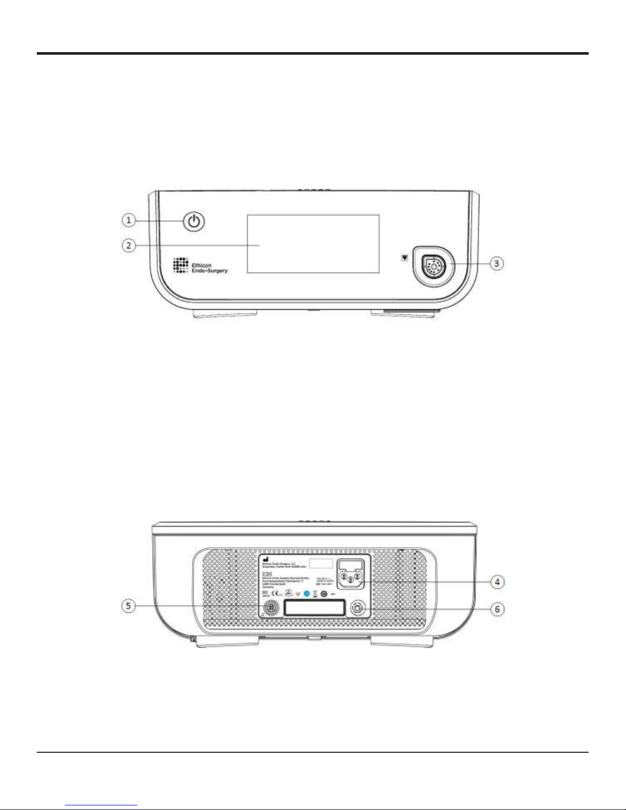
Illustration and Nomenclature
Front Panel of the Generator
Figure 1
Back Panel of the Generator
Figure 2

Generator G11 Service Manual
Footswitch
Figure 3
General Warnings

Generator G11 Service Manual
General Cautions
System Specifications
Maintenance and Repair
Customer Service
Warranty

Generator G11 Service Manual
Customer Service
Chapter 2 - Theory of Operation
Generator G11 Functionality Overview
Generator G11 Theory of Operation

Generator G11 Service Manual
Main PCB I/O Diagram
Figure 4
MEMORY
MEMORY
SERIAL
I/O PORT
DSP PROCESSOR FPGA
UI PROCESSOR
USB
PORTS (2)
LCD
BEZEL BOARD
TOUCH SCREEN
INTERFACE
AUDIO
AMP
POWER SUPPLY ENABLE
ON / OFF
PROCESSOR
DAC
ADC
ADC
ON/OFF BUTTON
TOUCH SCREEN
DAC
DAC
ADC
SWITCH-MODE
CONVERTER
BIAS
POWER SUPPLY ENABLE
SYSTEM VOLTAGES
AC LINE
POWER SUPPLY
PATIENT ISOLATED CIRCUITS
H1
E1
PR
SR
P
HS
ADC
R
S
ADC
SIGNAL
COND.
CKT.
XFM
XFM
FPGA
DATA CKT.
INTERFACE
DCI
ID
I
R
D
A
I
R
D
A
AMP
HS
*
HS
*
HS
*
HS - High Speed
H1 - Harmonic Power Output
E1 - EnSeal (RF) Power Output
PR - Power Return
P - Presence
HS - Hand Switch
ID - Identication / EEPROM
DCI - Data Circuit Interface
*
Main PCB I/O Diagram

Generator G11 Service Manual
Chapter 3 - Repair and Replacement Procedures
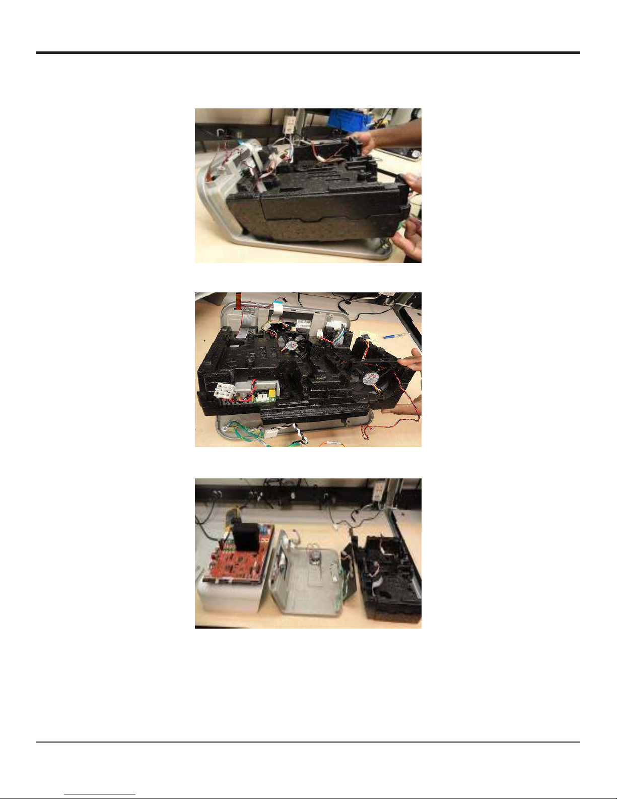
Bottom Cover and EPAC Removal Procedure
Figure 5
Note:
Figure 6
Figure 7

Generator G11 Service Manual
Figure 8
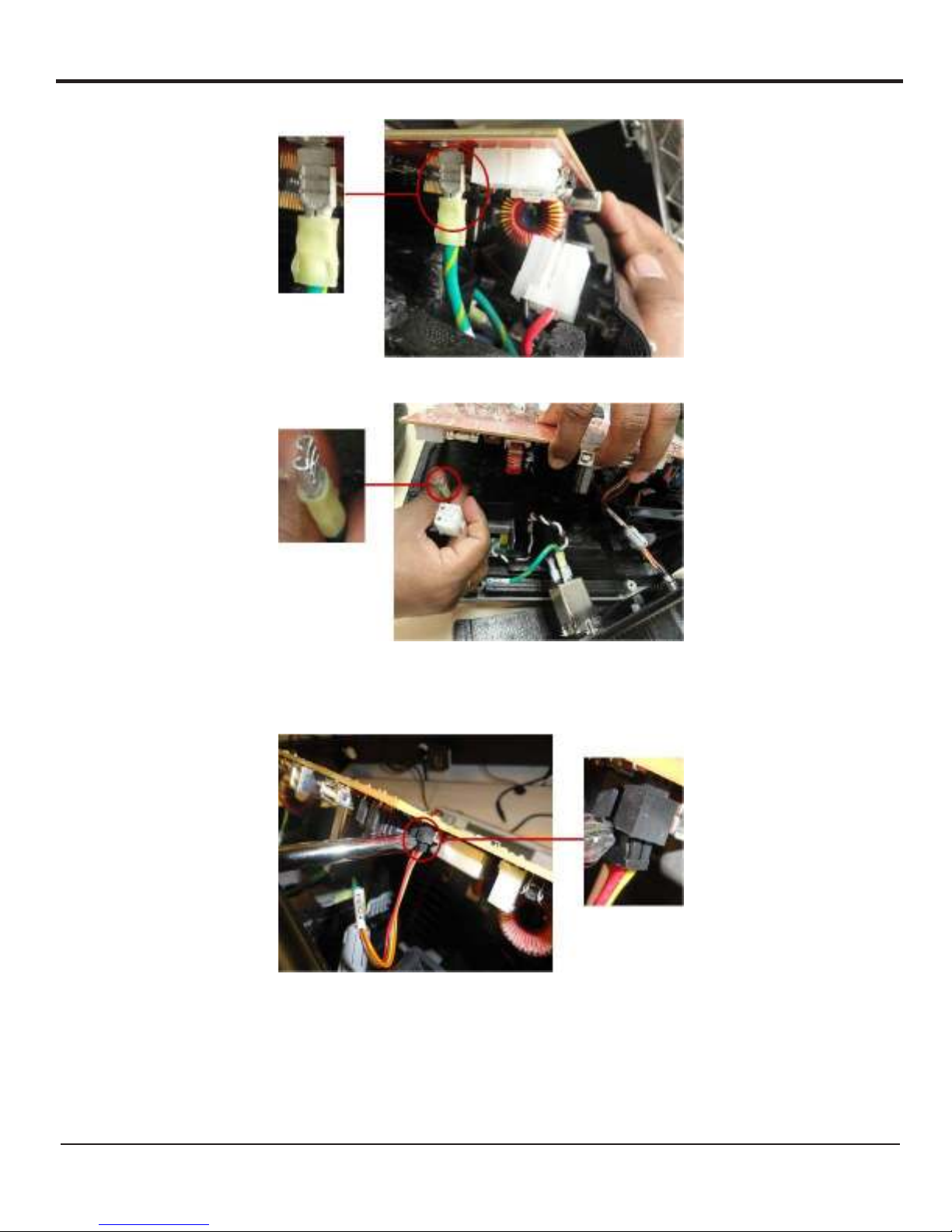
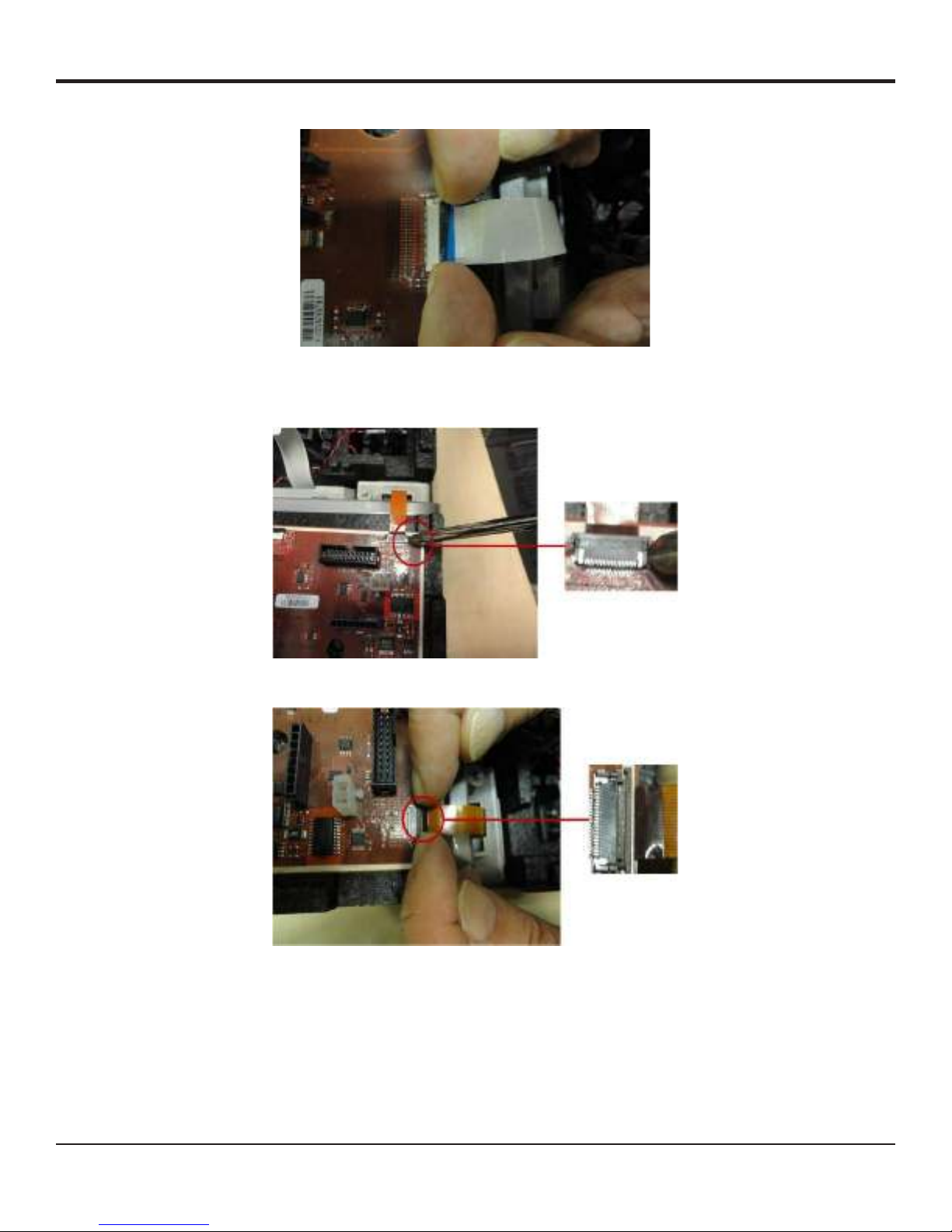
Main PCB Disassembly Procedure
Note:
Caution:
Figure 9
Figure 9a
Generator G11 Service Manual
Figure 9b
Figure 9c
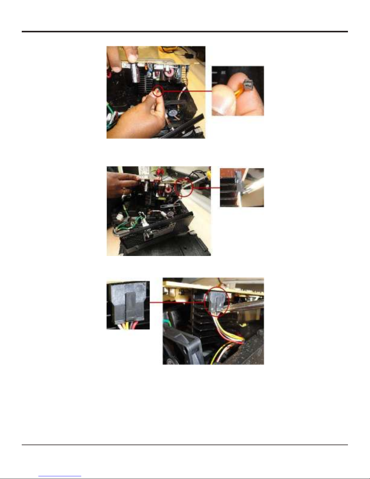
Figure 10
Generator G11 Service Manual
Figure 10a
Figure 11
Figure 11a

Generator G11 Service Manual
Figure 12
Figure 13
Figure 14
Generator G11 Service Manual
Figure 15
Figure 16
Figure 17

Generator G11 Service Manual
Figure 18
Figure 19
Figure 19a
Generator G11 Service Manual
Figure 19b
Figure 20
Figure 20a

Generator G11 Service Manual
Figure 20b
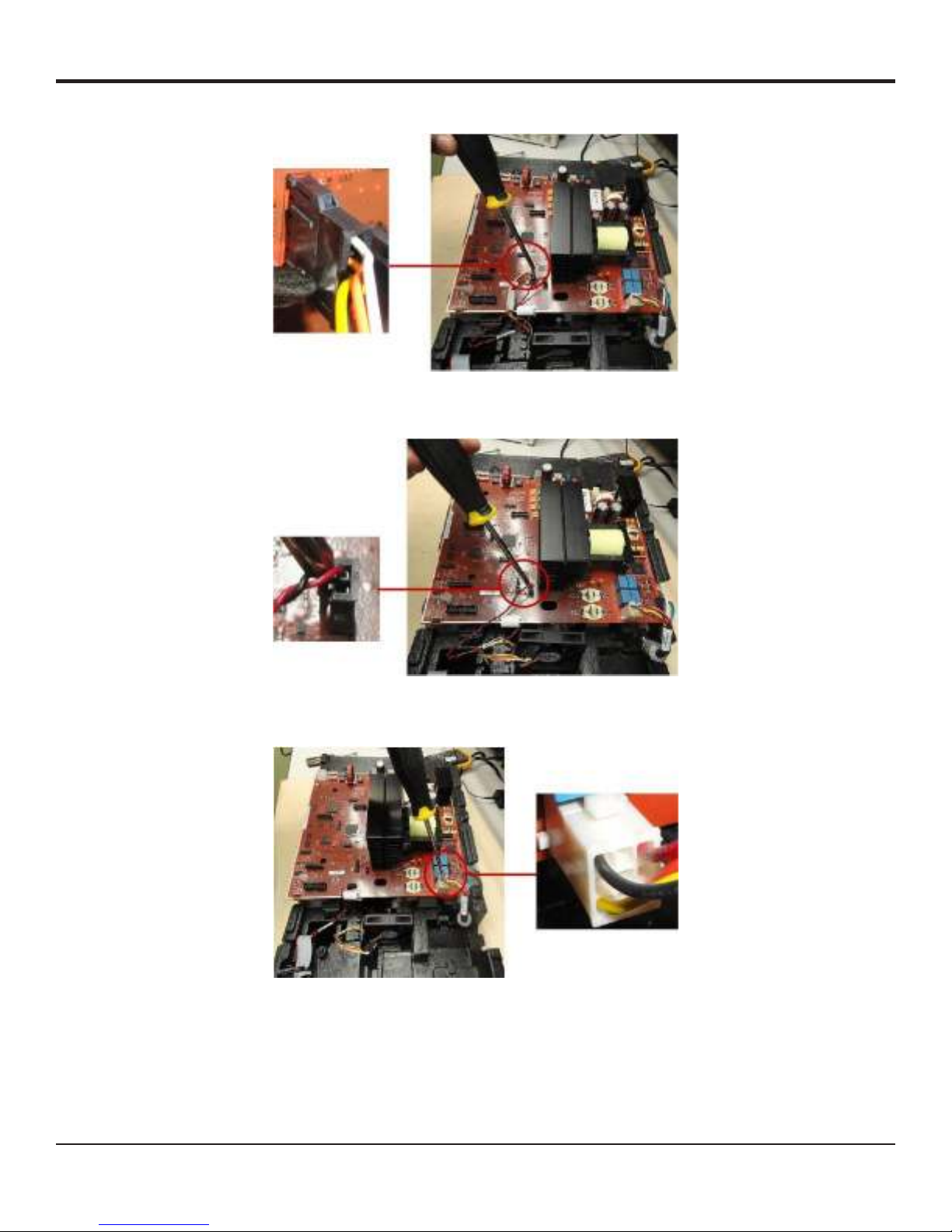
Power Module Disassembly Procedure
Figure 21
Figure 22
Generator G11 Service Manual
Speaker Removal Procedure
Figure 23
Figure 23a
Figure 23b

Generator G11 Service Manual
Note:
Figure 24
Connector / Device Receptacle Removal Procedure
Note:
Figure 25
Figure 26

Generator G11 Service Manual
Front Panel Disassembly Procedure
Note:
Figure 27
Figure 28
Figure 29
Other manuals for Generator G11
1
Table of contents
Popular Inverter manuals by other brands


Envertech
Envertech EVT360 user manual

hpmont
hpmont HD30-2D0P4G 1.0 5.8 2.5 0.4HD30-2D0P7G 1.5 10.5 4.0 0.75HD30-2D1P5G 2.8 18.5 7.5 1.5HD30-2D2P2GHD30-2T3P7G 5.9 19 17... user manual

Haier
Haier N-Series Service manual

Innovative Energies
Innovative Energies YK-PSW122KVA user manual

SOLARMG
SOLARMG 1.5K user manual

Intersoft Electronics
Intersoft Electronics RTG1002 user manual

INVT
INVT XG15KTR Operation manual

Grape Solar
Grape Solar GoCharger10 user manual

Omron
Omron JX - 1 System configuration

NOVA ELECTRIC
NOVA ELECTRIC CGL SERIES user manual

LIFAN Power USA
LIFAN Power USA Energy Storm Series Operating instructions and owner's manual

CPS
CPS SCH Series Installation and operation manual