THOR PPI Series User manual

THOR Manufacturing
7050 W. Palmetto Park Rd., Suite 15
Boca Raton, FL 33433
1-866-955-THOR
RD120808
California Proposition
65 Warning
WARNING: This product contains chemicals
known to the State of California to cause
cancer and/or reproductive harm, birth defects
or other reproductive harm.
ADVERTENCIA: Este producto contiene
productos quimicos reconocidos por el estado
de California que provocan cáncer o daños
reproductivo, defectos de nacimineto u otros
daños reproductivos.

PORTABLE POWER INVERTER
SAVE THIS INSTRUCTION MANUAL FOR FUTURE REFERENCE.
Copyright © 2018 THOR Manufacturing
Please register your product at www.thorpowerproducts.com .
In NO event shall THOR Manufacturing be liable for indirect, special or consequential damages.
Instruction Manual
and Warranty Information
PPI
Series
Portable Power Inverter
THMS
-500-PPI
THMS
-800-PPI

2
GENERAL SAFETY WARNINGS AND INSTRUCTIONS
READ ALL INSTRUCTIONS
WARNING: Read all instructions before operating your inverter. Failure to follow all instructions may result in
electric shock, fire and/or serious injury.
• AVOID DANGEROUS ENVIRONMENTS. Don’t use inverters in damp or wet locations.
• KEEP CHILDREN AWAY. Keep away from children. This is not a toy!
• STORE INDOORS. When not in use, inverters should be stored indoors in dry, and high or locked-up places – out
of reach of children.
• DON’T ABUSE CORD. Never carry inverter by cord or yank the cord to disconnect from receptacle. Keep cord
from heat, oil, and sharp edges.
• DISCONNECT INVERTER. Disconnect the inverter from the power supply when not in use.
• PROPER COOLING is essential when operating the inverter. Do not place it near a vehicle’s heat vent or in direct
sunlight.
• USE OF ACCESSORIES AND ATTACHMENTS. The use of any accessory or attachment not recommended by
manufacturer for use with this inverter could be hazardous.
• STAY ALERT. Use common sense. Do not operate inverter when you are tired.
• CHECK FOR DAMAGED PARTS. Any part that is damaged should be properly repaired or replaced by an
authorized service center unless otherwise indicated elsewhere in this instruction manual before further use. Do
not use inverter if switch does not turn it on and off.
• DO NOT OPERATE inverter near flammable liquids or in gaseous or explosive atmospheres. Motors in tools or
appliances used with the inverter may spark, and the sparks might ignite fumes.
SAFETY GUIDELINES AND DEFINITIONS
DANGER: Indicates an imminently hazardous situation which, if not avoided, will result in death or serious injury.
WARNING: Indicates a potentially hazardous situation which, if not avoided, could result in death or serious injury.
CAUTION: Indicates a potentially hazardous situation which, if not avoided, may result in minor or moderate injury.
CAUTION: Used without the safety alert symbol indicates potentially hazardous situation which, if not avoided, may
result in property damage.
RISK OF UNSAFE OPERATION. When using tools or equipment, basic safety precautions should always be
followed to reduce the risk of personal injury. Improper operation, maintenance or modification of tools or equipment
could result in serious injury and property damage. There are certain applications for which tools and equipment
are designed. Manufacturer strongly recommends that this product NOT be modified and/or used for any
application other than for which it was designed.
IMPORTANT SAFETY INSTRUCTIONS
WARNING: This product or its power cord may contain lead, a chemical known to the State of California to cause
cancer and birth defect or other reproductive harm. Wash hands after handling.
WARNING: TO REDUCE THE RISK OF ELECTRIC SHOCK:
• DO NOT connect to AC distribution wiring.
• DO NOT make any electrical connections or disconnections in areas designated as IGNITION PROTECTED. This
inverter is NOT approved for ignition protected areas.
• NEVER immerse the inverter in water or any other liquid, or use when wet.
• DO NOT insert foreign objects into the inverter’s outlets.
WARNING: TO REDUCE THE RISK OF FIRE:
• Do not operate near flammable materials, fumes or gases.
• DO NOT expose to extreme heat or flames.
CAUTION: TO REDUCE THE RISK OF INJURY OR PROPERTY DAMAGE:
• Remove appliance plug from outlet before working on the appliance.
• DO NOT attempt to connect or set up the inverter or its components while operating your vehicle. Not paying
attention to the road may result in a serious accident.
• ALWAYS use the inverter where there is adequate ventilation. Do not block ventilation slots.
• ALWAYS turn the inverter off and disconnect it from the power source when not in use.
• The inverter MUST be connected only to batteries with a nominal output voltage of 12 volts. The unit will not
operate from a 6 volt battery and will sustain permanent damage if connected to a 24 volt battery.
• When using this unit in a vehicle, check the vehicle owner’s manual for maximum power rating and recommended
output. DO NOT install in engine compartment — install in a well ventilated area.

3
• DO NOT use with positive ground electrical systems.* Reverse polarity connection will result in a blown fuse and
may cause permanent damage to the inverter and will void warranty.
*The majority of modern automobiles, RVs and trucks are negative ground.
• Keep in mind that this inverter may not operate high wattage appliances or equipment that produce heat, such as
hair dryers, microwave ovens and toasters.
• Do not open the inverter — there are no user-serviceable parts inside. Opening the inverter will void manufacturer’s
warranty.
• Do not use this inverter with medical devices. It is not tested for medical applications.
• Install and operate unit only as described in this Instruction Manual.
• Check inverter periodically for wear and tear. Return to manufacturer for replacement of worn or defective parts
immediately.
Read And Understand This Instruction Manual Before Using This Inverter.
SAVE THESE INSTRUCTIONS
WARNING: TO REDUCE THE RISK OF INJURY: FOLLOW THESE INSTRUCTIONS AND THOSE PUBLISHED
BY BATTERY MANUFACTURER AND THE MANUFACTURER OF ANY EQUIPMENT YOU INTEND TO USE WITH
THIS UNIT. REVIEW CAUTIONARY MARKINGS ON THESE PRODUCTS AND ON ENGINE.
TABLE OF CONTENTS
Introduction . . . . . . . . . . . . . . . . . . . . . . . . . . . . . . . . . . . . . . . . . . . . . . . . . . . . . . . . . . . . . . . . . . . . . . . . . . . . . . . . . . . . . . . . . 4
Features ...........................................................................................4
Controls and Functions................................................................................4
How These inverters work ...........................................................................5
Power Inverter Output Waveform ......................................................................5
Appliance Power Consumption..........................................................................6
Rechargeable Devices ..............................................................................7
Power Source and Protective Features ...................................................................7
Power Source Requirements .........................................................................7
Battery Configuration ...............................................................................8
Determining Battery Size ............................................................................8
Protective Features.................................................................................8
Installation ..........................................................................................9
Operating Environment..............................................................................9
Marine Applications.................................................................................9
Quick Operational Test or Emergency Use ..............................................................9
Permanent Installation (Cables and Fuse Not Supplied) ....................................................9
Important Cable Information: ........................................................................ 11
Operating Instructions................................................................................12
Operation of the 115 Volt AC Outlets ..................................................................12
Operation of the USB Charging Port ..................................................................12
Reading the DC Input Voltage and Output Power Indicators (back of unit) ....................................12
Notes on Using the Remote Control (sold separately).....................................................12
Troubleshooting Guide ...............................................................................13
Common Audio/Visual Problems .....................................................................13
Error Protection and Troubleshooting Guide ............................................................13
Care and Maintenance . . . . . . . . . . . . . . . . . . . . . . . . . . . . . . . . . . . . . . . . . . . . . . . . . . . . . . . . . . . . . . . . . . . . . . . . . . . . . . . 14
Storage .........................................................................................14
Fuse Replacement ................................................................................14
Preventive Maintenance ............................................................................14
Accessories......................................................................................14
Service Information................................................................................14
Full One-Year Home Use Warranty .....................................................................15
Warranty Activation ..................................................................................15
Specifications ......................................................................................15

4
INTRODUCTION
Thank you for purchasing this THOR Manufacturing Power Inverter. Please read this Instruction Manual carefully
before use to ensure optimum performance and to avoid damage to this product.
This power inverter is configured to supply continuous power in the form of 120 volt AC outlets and a USB port to
run or recharge most household or electronic appliances.
FEATURES
The Front Panel indicates power and proper operation of the inverter. This inverter can also display inverter fault
codes with the use of the TH-RC or the TH-IRC (Sold Separately). This also displays inverter fault codes, if the
inverter happens to shut down from over-load or over-temperature condition, or abnormal input voltages. The ON/
OFF Switch turns the inverter ON and OFF. The switch can also be used to force reset of inverter circuits by
switching it OFF, then back ON again. All models also feature a port to attach a remote control (sold separately).
120 volt AC power is supplied through two North American three-prong type outlets. The outlets can accommodate
either two- or three-pin AC plugs.
Controls and Functions
FRONT OF UNIT (ALL UNITS)
13
5
1. 2 x Three-Prong 120 Volt AC outlets
2. 2 x USB 2.1 Ports
3. LED Indicators
4. Mounting for secure fastenting.
5. Remote control port (Remote Sold Separately)
6. On / Off Switch
6
2
4

5
BACK OF UNIT (ALL UNITS)
7. Positive (+) DC Power Connection
8. High-Speed Cooling Fans
9. Negative (–) DC Power Connection
10. Grounding Post
79
8 10
HOW THESE INVERTERS WORK
Your inverter converts low voltage DC (direct current) electricity from a battery to 115 volt AC (alternating current)
household power in two stages. The first stage is a DC-to-DC conversion process that raises the low voltage DC
at the inverter input to 145 volts DC. The second stage converts the high voltage DC into 115 volts, 60 Hz AC.
Power Inverter Output Waveform
The AC output waveform of your inverter is known as a modified sine wave. It is a stepped waveform that has
characteristics similar to the sine wave shape of utility power. This type of waveform is suitable for most AC loads,
including linear and switching power supplies used in electronic equipment, transformers and small motors.
The modified sine wave produced by this inverter has an RMS (root mean square) voltage of 115 volts. Most AC
voltmeters (both digital and analog) are sensitive to the average value of the waveform rather than the RMS value.
They are calibrated for RMS voltage under the assumption that the waveform measured will be a pure sine wave.
These meters will not correctly read the RMS voltage of a modified sine wave. Non-TRUE RMS meters will read
about 20 to 30 volts low when measuring the output of this inverter. For accurate measurement of the output voltage
of this unit, use a TRUE RMS reading voltmeter such as a Fluke 87, Fluke 8080A, Beckman 4410 or Triplett 4200.
115 VOLT AC OUTPUT
Q: Why don't I measure rated voltages when using a
multimeter on my power inverter?
A. Most multimeters are designed to give correct RMS readings
when applied to sine waves, but not when they are applied to
other waveforms. They will read from 2% to 20% low in voltage.
Look for a voltmeter that brags about "True RMS" readings, and
that will read correctly no matter what the wave shape is

6
Q. Can I use an extension cord with my inverter?
A.Yes, no problem. If cables need to be run, it is best to keep
inverter as close as possible to batteries. Use extension cords
on the output side (Vac output) rather than extending the Vdc
cables. Tip: Contractors often need to mount the inverter in the
back of their trucks. In a case like this it would be best to mount
a secondary battery near the inverter and wire it to the primary
truck battery. Vac extension cords should not exceed 200 feet
or you will have signal loss.
Q. Can I Use a Power strips or surge protectors with my
inverter?
A. No, the use of surge protectors (also called surge
suppressors) or power strips are not recommended for use with
THOR Manufacturing inverters. This causes confusion with the
inverters on board GFCI circuit causing the inverter to enter a
fault condition.
Before connecting any appliance to a modified sine wave inverter, check with the manufacturer for recommendations
on what type of sine wave should be used with your appliance or equipment.
Some sensitive electronics such as medical equipment, laser printers, key machines and others require the use of
a pure sine wave inverter.
THOR Manufacturing also offers Pure sine wave inverters.
APPLIANCE POWER CONSUMPTION
Most electrical tools, appliances and electronic equipment have labels that show the unit’s power consumption in
amps, watts or both. To avoid inverter shutdown and possible damage to the inverter or equipment, do not exceed
the inverter’s wattage rating. To obtain a rough estimate of the current (in amperes) the power source must deliver
where the power consumption of the tool or device is given in watts AC, simply divide the power consumption of
the load by 10. For example, if a load is rated at 200 watts AC, the power source must be able to deliver: 200 divided
by 10 = 20 amperes.
Your inverter will operate most AC loads within its power rating. Some induction motors used in refrigerators,
freezers, pumps and other motor-operated equipment, require very high surge currents to start them. Your inverter
may not be able to start some of these motors even though their rated current draw is within specifications for this
power inverter.
If a motor refuses to start, observe the battery voltage using a DC voltmeter while trying to start the motor. If the
battery voltmeter drops below 11 volts while the inverter is attempting to start the motor, this may be why the motor
won’t start. Make sure the battery connections are tight and the power source battery (or batteries) is (are) fully-
charged. If the connections are good and the power source is charged, but the voltage still drops below 11 volts,
you may need to use a larger power source battery (or battery combination).
Your inverter has built-in overload protection so that if you do exceed the inverter’s output capacity continuously,
the unit will automatically shut down. Once the excess load is removed, the inverter can be restarted and resume
normal operation.
Note: To restart the inverter, turn it off, and then on again. The ON/OFF Switch is located on the inverter’s Front Panel (refer to
the “Control and Functions” section of this Instruction Manual).
The inverter powers resistive loads the easiest; however, larger resistive loads, such as electric stoves or heaters,
could draw more wattage than the inverter can deliver on a continuous basis.
CAUTIONS
Ensure that total continuous power consumption of all tools and appliances to be used simultaneously with your
inverter does not exceed the inverter’s continuous wattage rating. Also ensure that start-up wattage for inductive
loads does not exceed peak watts for more than a second.

7
Appliances such as microwave ovens will normally draw more than their rated current and could possibly overload
the inverter when operated simultaneously with other appliances. For example: A 600 watt microwave oven draws
approximately 940 watts.
Rechargeable Devices
CAUTIONS
• Some rechargeable devices are designed to be charged by plugging them directly into an AC receptacle. These
devices may damage the inverter or the charging circuit.
• When using a rechargeable device with your inverter, monitor its temperature for the initial ten minutes of use to
determine if it produces excessive heat. If excessive heat is produced, the device should not be used with your
inverter.
• This problem does not occur with most battery-operated appliances and tools. Most of these appliances use a
separate charger or transformer that is plugged into an AC receptacle.
• Your inverter is capable of running most chargers and transformers.
POWER SOURCE AND PROTECTIVE FEATURES
Power Source Requirements
Your inverter will operate from input voltages between 11 and 16 volts DC. If the voltage drops below 11 volts, an
audible low battery warning alarm will sound. If the input voltage drops below 10 volts DC, the inverter will shut
down. This feature protects the battery from being completely discharged.
The inverter will also shut down if the input voltage exceeds 16 volts. This protects the inverter against excessive
input voltage. Although the inverter has built-in protection against over voltage, it may still be damaged if the input
voltage exceeds 17 volts.
Your inverter is engineered to be connected directly to standard electrical and electronic equipment in the manner
described in the “Installation” section of this Instruction Manual. Do not connect the inverter to household or RV AC
distribution wiring. Do not connect the inverter to any AC load circuit in which the neutral conductor is connected to
ground (earth) or to the negative of the DC (battery) power source.
The inverter will operate most AC loads within its power rating. Some induction motors used in refrigerators,
freezers, pumps and other motor-operated equipment, require very high surge currents to start them. The inverter
may not be able to start some of these motors even though their rated current draw is within specifications for this
power inverter. If a motor refuses to start, observe the battery voltage using a DC voltmeter while trying to start the
motor. If the battery voltmeter drops below 11 volts while the inverter is attempting to start the motor, this may be
why the motor won’t start. Make sure the battery connections are tight and the battery (or batteries) is (are) fully-
charged. If the connections are good and the battery is charged, but the voltage still drops below 11 volts, you may
need to use a larger battery (or battery combination).
Inductive loads, such as TVs and stereos, require more current to operate than resistive loads of the same wattage
rating. Induction motors, as well as some TVs, may require two to six times their rated wattage to start up. Because
these inverters have a peak watt power rating, many such appliances and tools may be safely operated. The
equipment that needs the highest starting wattage are pumps and compressors that start under load. This
equipment can be safely tested. If an overload is detected, the inverter will simply shut down until the overload
situation is corrected.
CAUTIONS
• Exceeding recommended voltage limits will void manufacturer’s warranty.
• NEVER try to use your inverter with any 12 volt DC power source that uses a positive ground. (Most vehicles and
boats use negative ground systems.)
• The Power Inverter must be connected only to batteries with a nominal output voltage of 12 volts. The unit will not
operate from a 6 volt battery and will sustain permanent damage if connected to a 24 volt battery.
• Reverse polarity connection will result in a blown fuse and may cause permanent damage to the inverter.

8
Battery Configuration
Note: For heavy-duty use, manufacturer recommends an ANL fuse be added as close as possible to the power source (battery)
positive terminal. The fuse amperage must be appropriate to allow simultaneous operation of all the AC appliances to be
powered, with delay characteristics that allow for the momentary high start-up current requirements of inductive loads.
Use the recommended fuse block (fuse holder) and fuse, or an electrical equivalent. See the “Specifications” section of
this Instruction Manual to determine the proper fuse for your inverter. For full rated and motor start-up surge output,
ensure that the installation is configured to handle the full load.
Determining Battery Size
To determine the minimum battery size you will need to operate appliances from your inverter, follow these steps:
1. Determine the wattage of each appliance and/or tool you will need to simultaneously operate from the inverter.
To do this, read the labels on the equipment to be operated.
2. Estimate the number of hours the equipment will be in use between battery recharges.
3. Determine the total watt-hours of energy use, the total running time and the average power consumption.
Keep in mind that some appliances are not drawing the same power continuously. For example, a typical home-use
coffee maker draws 500 watts during brew time (approx. 5 minutes) but maintains the pot temperature at only about
100 watts. Typical use of a microwave is only for a few minutes, sometimes at low power.
Protective Features
The inverter has electronic circuit protection against overload and short circuit conditions; and monitors for the
following potentially hazardous conditions:
Low Battery Voltage —This condition is not harmful to the inverter, but could damage the power source. An alarm
will sound when input voltage drops below 10.5 volts, and the inverter will automatically shut down when input
voltage drops below 10.0 volts. This indicates that the DC (battery) power source needs to be charged, or there is
an excessive voltage drop between the battery power source and the inverter. When the condition is corrected, the
inverter will automatically restart.
Over Voltage Protection — The inverter will automatically shutdown when input voltage exceeds 16 volts DC.
Overload Protection — The unit will automatically shut down when the continuous draw exceeds the inverter’s
wattage rating. Reduce the load and manually restart.
Over Temperature Protection — If the temperature inside the inverter reaches 150°F, the unit will automatically
shut down. Allow the inverter to cool for at least 15 minutes before restarting after a heat-related shutdown. Unplug
the inverter from the power source and disconnect all appliances or tools from the inverter’s outlets while cooling.
If the Digital display on the optional TH-IRC or TH-RC, displays a fault code follow the steps outlined in the
“Troubleshooting” section of this Instruction Manual. The Fault LED will light if there is an excessive voltage drop
between the (battery) power source and the inverter.
Note: Reverse polarity or short circuit condition may cause external or internal fuses to open and may cause irreversible
damage to the Power Inverter. Take extra care to ensure a proper polarity hook-up.
CAUTION
• If turning the ON/OFF Switch off, then on again does not reset the inverter, DO NOT ATTEMPT TO OPEN THE
INVERTER. Opening the inverter for any reason will void the warranty. The unit must be returned to manufacturer
for testing and repair by professional factory technicians.

9
INSTALLATION
Your inverter will provide you with continuous electrical power when powered by a reliable 12 volt DC source, such
as a vehicle battery or a multiple battery configuration. This manual does not describe all of the possible
configurations.
Operating Environment
For best operating results, your inverter should be placed on a flat surface, such as the ground, car floor or seat or
other solid surface to help diffuse the heat that is generated. Position the inverter as close to the DC power source
as possible.
The inverter should only be operated in locations that meet the following criteria:
DRY – Do not allow water and/or other liquids to come into contact with the inverter.
COOL – Ambient air temperature should be between 30°F (–1°C) non-condensing and 105°F (40°C). Do not place
the inverter on or near a heating vent or any piece of equipment that is generating heat above room temperature.
Keep the inverter out of direct sunlight.
VENTILATED – Allow at least three inches of clearance from other objects to ensure free air circulation around the
inverter. Never place items on or over the inverter during operation.
SAFE – Do not locate inverters in an area, room or compartment where explosives or flammable fumes might be
present, such as engine rooms, engine compartments and boats or small, unvented battery compartments.
Marine Applications
In all marine applications, DO NOT install the inverter below or near the waterline; and keep the inverter away from
moisture and water.
Use ONLY non-corrosive marine fasteners and fittings for installation. Only connect the inverter’s DC input to
existing wiring (that has been approved for marine use) at the appropriate gauge, cable and length. The cable, fuse
holder and fuse (not supplied) can be purchased at an electrical supply company. Call the manufacturer for
additional installation information.
Quick Operational Test or Emergency Use
You will need:
• A heavy-duty jumper cable set of the specified AWG wire rating (refer to the “Installations” section of this
Instruction Manual)
• A fully-charged automobile battery
• A common slip joint plier for loosening and tightening terminal nuts
PROCEDURE
1. Unscrew nuts in input terminal block.
2. Identify the positive and negative terminals on the 12 volt DC battery (or other 12 volt DC power source) and
identify the positive and negative terminals on the inverter.
3. Using a set of heavy-duty jumper cables, attach the red cable to the inverter’s positive (+) terminal and the black
cable to the inverter’s negative (–) terminal. 4. Connect the clamps on the other ends of the jumper cables to
the corresponding positive (+) and negative (–)
4. Connect the clamps on the other ends of the jumper cables to the corresponding positive (+) and negative (–)
terminals on the 12 volt DC vehicle battery (or other 12 volt DC power source). There may be some minor
sparking.
5. Turn the inverter ON/OFF Switch on.
6. Plug in a lamp with a 100 watt light bulb and switch the lamp on. If the lamp works normally, the inverter is
functioning properly and you can proceed to a permanent installation or continue to use the inverter with low
wattage appliances. If the lamp does not light or does not work correctly:
A. Check all connections and tighten any that may be loose.
B. Ensure that the source battery has adequate charge.
C. If steps A and B do not correct the problem, refer to the “Service Information” section of this Instruction
Manual for assistance.

10
Permanent Installation (Cables and Fuse Not Supplied)
For permanent installation to heavy-duty battery power you will need:
• Two cables (as indicated in the “Specifications” section of this Instruction Manual)
• Terminals to fit cable ends and stud terminals to inverter
• Hardware and battery connector to connect cables to the battery bank
• A single length of AWG cable multi-stranded, flexible, insulated cable (as indicated in the “Installations” section of
this Instruction Manual) for chasis ground connection when using inverter in a household application.
• A holder and fuse (see the “Specifications” section of this Instruction Manual)
• Mounting screws, bolts and nuts for mounting the inverter and fuse holder
• A drill for mounting the inverter and fuse holder
• Lead-tin solder, flux, propane torch and an igniter for the torch
• Wire stripper/cutting tool
PRELIMINARY STEPS
The inverter has four slots in its mounting bracket that allow the unit to be fastened against a bulkhead, floor, wall
or other flat surface. Ideally, the mounting surface should be cool to the touch. It is more efficient to use longer AC
wiring than DC wiring, so install the inverter as close as possible to the 12 volt DC power source.
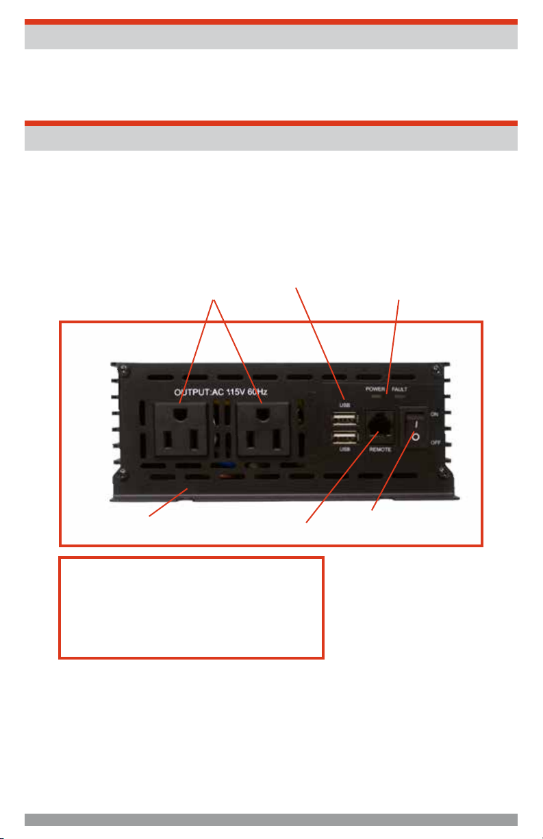
The inverter should be operated in horizontal position; if it is to be mounted on a wall, mount it horizontally so that
indicators, switches, outlets and terminal blocks on the front panel are visible and accessible.
1. If inverter is to be installed in a vehicle, manufacturer recommends that it be shock mounted to either the floor
(in a clear, safe area) or on a secure flat surface.
2. Locate a convenient place to mount the inverter and fuse holder.
3. Perform a test routing of the proposed cable length, but don’t do any cutting at this time (refer to the diagram
in the “Battery Configuration” section of this Instruction Manual).
4. Using an appropriate AWG cable (refer to the “Specifications” section of this Instruction Manual), reposition the
inverter and fuse holder if necessary.
5. After you have performed the above preliminary installation steps, proceed with the actual inverter installation.
Contact the manufacturer for any further installation information or questions.
Permanent Installation Procedure
IMPORTANT: Please follow installation and wiring instructions exactly as outlined to ensure safety. We
recommend installation by an RV technician or professional electrician to ensure adherence to relevant
electrical codes. We have made every reasonable effort to ensure the accuracy of the instructions in this
manual, but THOR Manufacturing does not guarantee that the information is error free, nor do we make any
other representation, warranty or guarantee that the information is accurate, correct, reliable or current. The
specifications in this manual are for reference purposes only and are subject to change without notice.
DISCLAIMER: THOR Manufacturing disclaims liability for any direct, indirect or incidental damages caused by,
or in case of, installation not performed following the instructions and cautions in this manual. THOR
Manufacturing will refuse requests for exchanges or returns, resulting from the purchase and installation of
items which do not comply with local codes. To avoid such concerns THOR Manufacturing recommends
installation by a professional electrician or RV technician. Examples that are shown within this manual are for
illustrative purposes only.
WARNING: Lethal currents will be present if the positive and negative cables attached to the battery bank touch
each other. During the installation and wiring process, ensure the cable ends are insulated or covered to
prevent shorting the cables. WARNING: DO NOT connect the DC Wires from the battery bank to the THOR
Manufacturing unit until all the DC and AC wiring is complete and the AC and DC overcurrent protection has
been installed.
WARNING: The Inverter is not reverse polarity protected. If the Inverter is wired incorrectly severe damage will
occur and will not be covered by the warranty. It is advised to clearly mark the positive and negative cables
coming from the battery bank. Use red and black electrical tape to clearly indicate positive and negative cables.
CAUTION
• Loose connectors may cause overheated wires and melted insulation.

11
• Check to make sure you have not reversed the polarity. Damage due to reversed polarity is not covered by
manufacturer’s warranty.
GROUNDING THE INVERTER - AC GROUNDING
THOR Manufacturing inverters should always be connected to a permanent, grounded wiring system. An Inverter
that is properly grounded will reduce the risk of electric shock, reduce radio frequency noise. The main aim of any
grounding system is to provide a well-defined, very low resistance path from the electrical system to the grounding
system. The low resistance grounding path carries fault currents directly to ground if the electrical system
malfunctions.
Grounding the power inverter has a lug on the rear panel: "Chassis Ground." This is to connect the chassis of the
power inverter to the ground. The ground terminals in the AC outlets on the front panel of the inverter are also
connected to the ground lug. To ground your THOR Manufacturing inverter, connect grounding wire to one of the
mounting screws and sand the connection before attaching the wire. The chassis ground lug must be connected to
a grounding point, which will vary depending on where the power inverter is installed. In a vehicle, connect the
chassis ground to the chassis of the vehicle. In a boat, connect to the boat's grounding systems. In a fixed location,
connect the chassis ground lug to earth. The neutral (common) conductor of the power inverter AC output circuit is
not bonded to the chassis ground. Therefore, when the chassis is connected to ground, the neutral conductor will
not be grounded. At no point should the chassis ground and the neutral conductor of the inverter be bonded.
Bonding the chassis ground and the neutral conductor of the inverter or connecting the inverter to household or
recreational AC distribution wiring will damage the unit and void the warranty.
CAUTION This inverter cannot supply power to any AC distribution wiring or AC loads in which the neutral and
ground are connected (bonded). Doing so will destroy the unit and void the warranty. If you do not understand
neutral to ground bonding then please have a professional install your system for you. See “Grounding” for more
information.
CAUTION Do not connect this inverter and another AC source (generator or utility power) to the AC wiring or AC
loads at the same time. Doing so will destroy the inverter and void the warranty, regardless whether the inverter is
switched on or off. If you are using more than one AC source for the AC wiring or AC loads, it is highly recommended
that you install an automatic transfer switch (THTS), available from THOR Manufacturing
IMPORTANT CABLE INFORMATION:
Substantial power loss and reduced battery operating time results from inverters installed with cables that are not
able to supply full power. Symptoms of low battery power can result from cables that are either excessively long or
an insufficient gauge. Marine installations are also subjected to vibration and stresses that exceed those of other
mobile installations. Therefore, the installer/operator should be especially aware of the requirements to maintain
secure, tight, water-resistant electrical connections and to provide for strain relief for DC cables and appliance
wiring. Cable insulation must be the appropriate type for the environment.

12
OPERATING INSTRUCTIONS
CAUTION: Make sure the combined load requirement of your equipment does not exceed your inverter’s
maximum continuous power.
Operation of the 120 Volt AC Outlets
This unit features two 115 volt AC GFCI (ground fault circuit interrupter) protected outlets, that function in the same
way as GFCI outlets you would typically use in your home. GFCI outlets are intended to protect equipment by
interrupting the circuit if current leakage exceeds 5 mA of current within 25 milliseconds.
1. Connect the inverter to a functioning 12 volt DC power source as described in this Instruction Manual. Make
sure there is adequate space for proper ventilation of the inverter.
2. Press the Power Pushbutton to turn the unit ON.
3. The Power Inverters Display will will light green, indicating a proper connection. If the Power/Fault LED
Indicator lights red, indicating a fault condition exists, refer to the “Troubleshooting” section of this Instruction
Manual.
4. Plug the (110/120 volt AC) appliance into one of the Inverter’s three-prong AC outlets and operate normally.
Note: The Inverter will not operate appliances and equipment that generate heat, such as hair dryers, electric blankets,
microwave ovens and toasters.
Remember to disconnect the inverter from any power source when not in use.
Operation of the USB Charging Port
1. Connect the inverter to a functioning 12 volt DC power source as described in this Instruction Manual. Make
sure there is adequate space for proper ventilation of the inverter.
2. Press the Power Pushbutton to turn the unit ON.
3. The display will light up , indicating a proper connection. If the display, displays a fault code, indicating a fault
condition exists, refer to the “Troubleshooting” section of this Instruction Manual.
4. Plug the USB-powered device into the inverter’s USB Charging Port and operate normally.
Note: This unit’s USB Charging Port does not support data communication. It only provides 2.1 Amps 5Volts DC power to an
external USB-powered device.
Remember to disconnect the inverter from any power source when not in use.
Notes on Using the Remote Control (sold separately)
The manufacturer offers (as a separate item) a Remote Control specifically designed for this line of inverters. The
inverter On/Off Switch must be in the off position when connecting the Remote Control to the unit, or the Remote
Control will not operate. Once the unit has been turned on using the Remote Control, inverter operation will continue
to be controlled through the Remote Control. Turn the inverter off before disconnecting the Remote Control. For more
information about attaching and using the Remote Control, please refer to the Remote Control Instruction Manual.
TROUBLESHOOTING GUIDE
Common Audio/Visual Problems
PROBLEM SOLUTION
“Buzzing” sound in
audio systems
Inexpensive stereo systems and “boom boxes” may emit a buzzing sound from their
speakers when operated from your inverter. This occurs because the power supply in
the electronic device does not adequately filter the modified sine wave produced by the
inverter. The only solution to this problem is to use a higher quality sound system.

13
PROBLEM SOLUTION
Television
Interference
Your inverter is shielded to minimize interference with TV signals. However, in some
instances, some interference may still occur, particularly where TV signals are weak.
Try the following corrective measures:
• Place the inverter as far as possible from the television. Use an extension cable, if
necessary.
• Readjust the orientation of the inverter, the antenna cables and the TV power cord to
minimize interference.
• Make sure the antenna feeding the television provides an adequate (“snow free”)
signal and that high quality, shielded antenna cable is used.
• Do not use the inverter to operate high-power appliances or tools at the same time
you are using it to operate the TV.
• Make sure the inverter’s case is properly grounded (refer to the “Permanent
Installation Procedure” section of this Instruction Manual).
Error Protection and Troubleshooting Guide **Requires TH-IRC or TH-RC
Display Indications, Common Problems, Possible Solutions / Indicacion, Causa Posible, Solucion Posible
LOW DC INPUT VOLTAGE (Below 10Vdc)
• Battery Voltage too low, Check or Recharge (battery) Power Source
• Inadequate power being delivered to the inverter or excessive voltage drop. Use heavier gauge wire
• See “Installation Specications” in users manual
APAGADO DE BAJA ENTRADA DE VOLTAJE
• Voltaje de la fuente (batería ) demasiado baja Recargue o substituya la ( batería) Fuente de alimentación
• Potencia inadecuada entregado al inversor o excesiva caída de Voltage .
• Consulte“Especicaciones de instalación” en el manual del usuario
HIGH DC INPUT VOLTAGE ( Above 16Vdc)
• Battery Voltage is too high, Check for fault with battery charging system
APAGADO DE ALTA ENTRADA DE VOLTAJE
• Voltaje de la batería es demasiado alto, Compruebe si hay fallas en el sistema de carga de la batería
OVERLOAD SHUTDOWN
• Excessive start-up load. Power tool (or appliance ) draws too much voltage; and cannot be used with your inverter
• Inadequate power being delivered to the inverter or excessive voltage drop . Use heavier Gauge wire.
• See “Installation Specications” in users manual.
APAGADO DE SOBRECARGA
• Excesivo Carga de arranque.
• Potencia inadecuada entregado al inversor o excesiva caída de Voltage .
• Consulte“Especicaciones de instalación” en el manual del usuario.
OVER TEMPERATURE
• Inverter is too hot (thermal shutdown mode) Allow Inverter to cool. Check for adequate ventilation.
• Reduce the load on the inverter to rated continuous output.
APAGADO DE ALTA TEMPERATURA
• Inversor está demasiado caliente.
• Permita inversor que se enfríe . Compruebe si hay una ventilación adecuada para el inversor .
• Reduzca la carga en el inversor .
GROUND FAULT PROTECTION / SHORT CIRCUIT PROTECTION
• Inverter senses a leakage current on the ground terminal or short circuit current on the AC sockets. Unplug the AC appliance or
power tool. Turn o the inverter, disconnect unit from any 12 VDC power source. Check the appliance or power tool and cord.
PROTECCION DE FUGA
• Inversor detecta una corriente de fuga.
• Inversor detecta corriente de cortocircuito.
• Desenchufe el aparato de CA o herramienta eléctrica
E 01
E 02
E 03
E 04
E 05
No FUNCTION - (If inverter digital display does not illuminate.)
• Check and make sure the inverter is properly connected to (battery) Power Source .
• See “Installation Specications” in users manual.
Resetting the Inverter
After over-voltage or thermal automatic shutdown, your inverter will reset automatically.
CARE AND
MAINTENANC
Storage
1. Ideal storage temperature range is 50-68°F (10-20°C).
2. Store and use the inverter in a cool, dry place with adequate ventilation.

14
3. Avoid locations that are exposed to heating units, radiators, direct sunlight or excessive humidity or dampness.
Fuse Replacement
Your inverter is equipped with multiple internal fuses. Normally, these fuses will not “blow” unless there is a serious
problem inside the unit. Internal fuses are replaceable; however, only trained personnel should attempt fuse
replacement. Refer to the “Service Information” section of this Instruction Manual.
Preventive Maintenance
MAINTENANCE AND TROUBLESHOOTING THOR Manufacturing inverters are designed to be service-free, even
though there are no user serviceable parts, it is recommended that every 6 months you perform the following
maintenance steps to ensure optimum performance and extend the life of your batteries and power inverter. •
Visually inspect the batteries for cracks, leaks or swelling - replace if necessary.
• Use baking soda to clean and remove any electrolyte spills or buildups.
• Check and tighten all battery terminal connections.
• Check and fill battery water levels in flooded lead acid batteries.
• Check individual battery voltages (load test those that have a voltage difference of more than 0.3 VDC from each
other) replace if necessary.
• Check the Inverter / Chargers ventilation vents - clean if necessary.
• Visually inspect all cables in both the DC and AC systems - check for wear/abrasion - replace if necessary and
ensure strain reliefs and cable protection is installed to prevent future damage.
• Check and tighten the Inverter / Chargers AC terminal block connections.
• Check the ground connections are secure on the Inverter / Charger, Battery Bank, Main / Sub Panels and the
Earth Ground on the RV, Boat.
ACCESSORIES
If you need assistance regarding accessories, please call: 1-866-955-THOR or visit www.thorpowerproducts.com.
WARNING: The use of any accessory not recommended for use with this tool could be hazardous and will void
manufacturer’s warranty.
Inverter Install Kits are available from THOR Manufacturing! (Sold Separately) Installation Kits include everything
you will need to properly connect your THOR Manufacturing power Inverter to the batteries. Visit our website for more
details
www.thorpowerproducts.com
SERVICE INFORMATION
To locate your nearest service location or for details on replacement parts, contact the manufacturer at 1-866-955-
THOR.
LIMITED ONE-YEAR HOME USE WARRANTY
The limited warranty program is the only one that applies to this unit, and it sets forth all the responsibilities of THOR
Manufacturing. There is no other warranty, other than those described herein. Any implied warranty of merchantability
of fitness for a particular purpose on this unit is limited in duration to the duration of this warranty.
This unit is warranted, to the original purchaser only, to be free of defects in materials and workmanship for one year
from the date of purchase without additional charge. The warranty does not extend to subsequent purchasers or
users.
Manufacturer will not be responsible for any amount of damage in excess of the retail purchase price of the unit under
any circumstances. Incidental and consequential damages are specifically excluded from coverage under this
warranty.

15
SPECIFICATIONS
THMS500-PPI THMS800-PPI
Output Voltage /
Voltage De Slida 120 +- 5 Vac / 120 +- 5 VDC 120 +- 5 Vac / 120 +- 5 VDC
Output
Frequency /
Frecuencia De
Salida
60 Hz 60 Hz
Output
Waveform /
Forma De Onda
Modified Sine Wave / Onda Sinusoida Modificada Modified Sine Wave / Onda Sinusoida Modificada
Max. Continuous
Active Power
Output / Slida
De Corriente
Continua
500 Watt / 500 Vatios 800 Watt / 800 Vatios
Max. Active
Surge Power
Output (<.5 Sec)
/ Salida De
Corriente Para
Pico
1000 Watt / 1000 Vatios 1600 Watts / 1600 Vatios
Peak Efficiency /
Punto Mas Alto
De Eficiencia
>85 % >85 %
This unit is not intended for commercial use. This warranty does not apply to damage to units from misuse or
incorrect installation/connection. Misuse includes wiring or connecting to improper polarity power sources.
RETURN / REPAIR POLICY
Before contacting THOR Manufacturing’s customer service department, please read the “frequently asked
questions” section of our website to troubleshoot the problem. If trouble persists: 1. Call your THOR Manufacturings
Technical Support team (1-866-955-THOR) or 2. Return defective product to place of purchase. Unless approved
by THOR Manufacturing Management, all product shipped collect to THOR Manufacturing will be refused. Test
items or items that are not under warranty, or units that are not defective, will be charged a minimum bench charge
of ($50.00 US) plus taxes and shipping. A 15% restocking charge will be applied on goods returned and accepted
as “new” stock. An RMA number (Return Materials Authorization number) from THOR Manufacturing’s Customer
Service is required prior to returning any THOR Manufacturing products. THOR Manufacturing reserves the right
to refuse any items sent to THOR Manufacturing without an associated RMA number.
Out of Warranty THOR Manufacturing product! electronic products are non-repairable, THOR Manufacturing, does
not perform repairs on its products nor does it contract out those repairs to a third party. THOR Manufacturing does
not supply schematics or replacement parts for any of its electronic products.
WARRANTY ACTIVATION:
Please complete the Warranty Registration Form on the THOR Manufacturing website http://thorpowerproducts.com/
register-product/. Enter the model number and product type and serial number. All THOR Manufacturing products
must be registered within 30 days of purchase to activate this warranty.
This warranty does not apply to accessories. This warranty gives you specific legal rights and you may have other
rights which vary from state to state or province to province. Should you have any questions, contact the THOR
Manufacturing at 1-866-955-THOR. This product is not intended for commercial

16
THMS500-PPI THMS800-PPI
Over
Temperature /
Apagado De Alta
Temperatura
Yes (Auto Reset) / Si (Auto-Reinicio) Yes (Auto Reset) / Si (Auto-reinicio)
High DC Input
Voltage /
Apagado De Alta
Entrada De
Voltage
> 16.5VDC > 16.5VDC
Low DC Input
Voltage Cut Off /
Apagado De
Baja Entrada De
Voltage
< 9.5 VDC < 9.5 VDC
Low DC Input
Voltage Alarm /
Alarma De Baja
Entrada De
Voltage
<10.5 VDC <10.5 VDC
DC Input
Connections /
Conexion De
Entrada VCD
Twist Down Input Lugs / Atornille Agarraderas De
Entrada
Twist Down Input Lugs / Atornille Agarraderas De
Entrada
Ac Output
Connections /
Conexcion De
Salida - No De
Recipientes
Nemas-15R
2 2
Remote Control
Connection /
Puerto De
Control Remoto
Yes / Si Yes / Si
Remote Control
(Optional) /
Control Remoto
20 Foot Remote Control / Control Remoto Con Cable 20
Pies
20 foot remote control / Control Remoto Con Cable 20
pies
Dimensions (W
X D X H) /
Dimensiones (L
X Anch X Alt)
L 7.88 * W 7.81 * H 2.63” L 10.47 * W 6.61 * H 2.63”
Weight (Lbs) /
Peso, Lb 2.55 LBS 4.10 LBS

17
THOR MANUFACTURING LIMITED WARRANTY
Limited Product Warranty and Exclusions
THOR Manufacturing provides a limited warranty that covers defects of your products. The warranty period is for 1
year and begins on the date of purchase by the original end user. Warranty claims may only be made by, or on the
behalf of, the original end customer.
THOR Manufacturing will, at its option, repair or replace the defective component(s) free of charge, provided that
THOR Manufacturing is notified of the defect during the warranty period and a dated proof of purchase is furnished.
THOR Manufacturing reserves the right to inspect the faulty component(s) and determine if the defect is due to
material or manufacturing flaws. THOR Manufacturing also reserves the right to charge for service time expended
if the defect is not due to material or manufacturing flaws or is not for some other reason subject to this limited
warranty.
THOR Manufacturing does not warrant inverters from any and all defects or damage caused by:
a) Normal wear and tear
b) Shipping or transportation damages
c) Improper installation
d) Exposure to unsuitable environmental conditions (including but not limited to damage due to lightning strikes)
e) Unauthorized or abnormal use or operation
f) Negligence or accidents
g) Material or workmanship not provided by THOR Manufacturing or its authorized service centers
h) This warranty does not cover costs related to the removal, installation, or troubleshooting of your electrical
systems
i) Any accessories used with the inverter that is not manufactured by THOR Manufacturing
THOR Manufacturing will, at its option, use new and/or reconditioned parts in performing warranty repair and in
building replacement products. THOR Manufacturing reserves the right to use parts or products of original or
improved design in the repair or replacement. If THOR Manufacturing repairs or replaces a product, its warranty
continues for the remaining portion of the original warranty period or 90 days from the date of the return shipment
to the customer, whichever period expires later. All replaced products and all parts removed from repaired products
become the property of THOR Manufacturing. THOR Manufacturing covers both parts and labor necessary to repair
the product and return shipment to the customer, via a THOR Manufacturing selected non-expedited surface freight
carrier within the continental United States. The warranty does not cover any cost associated with installation,
removal or re-installation of the Inverter.
Limitation of Warranty Scope
a) THOR Manufacturing makes no warranty of any kind, express or implied, including without limitations the implied
warranty only applies to THOR Manufacturing branded products. All other name brand products are warranted by
and according to their respective manufacture. Please do not attempt to return non-THOR Branded products to
THOR Manufacturing.
b) In No event shall THOR Manufacturing be liable for indirect, special or consequential damages.
c) The use of accessories not recommended by the manufacturer could lead to damage to the device
or equipment
d) Do not use accessories or attachments not recommended by the receiver manufacturer, as they may cause
hazards and will void the warranty.
e) Any use of accessories, attachments or spare parts not recommended by the manufacturer may result in fire,
electric shock and injuries to persons.
d. Damage caused by inexpert treatment or operation, and damage resulting from the use of non-original parts or
accessories not recommended by THOR Manufacturing is not covered by the warranty.
This manual suits for next models
2
Table of contents
Other THOR Inverter manuals

THOR
THOR THPS-600R-12 User manual

THOR
THOR TH225 User manual

THOR
THOR TH225 Instruction Manual

THOR
THOR PW Series User manual

THOR
THOR THPS 1000 Series User manual

THOR
THOR TH1000 Instruction Manual

THOR
THOR MS Series User manual

THOR
THOR THMS-1000 User manual

THOR
THOR THPW-1000 User manual

THOR
THOR THPW1500-ETL Instruction Manual