ETI Solid State Lighting WR-2-20-940-MV-D User manual

USE AND CARE GUIDE
2 FT. /4 FT.LED WRAP LIGHT
Questions, problems, missing parts?
Call ETi SSL Customer Service
9 a.m. – 5 p.m., EST, Monday - Friday
1-855-ETI-SSLI (1-855-384-7754)
www.ETiSSL.com
THANK YOU
products designed to enhance your home. Visit us online to see our full line of products available for your home improvement needs.
Thank you for choosing ETi!
Model #
54655441
54676241
Part #
WR-2-20-940-MV-D
WR-4-40-940-MV-D

2
Table of Contents
Table of Contents ................................... 2
Safety Information .................................. 2
Warranty .......................................... 2
Pre-Installation..................................... 3
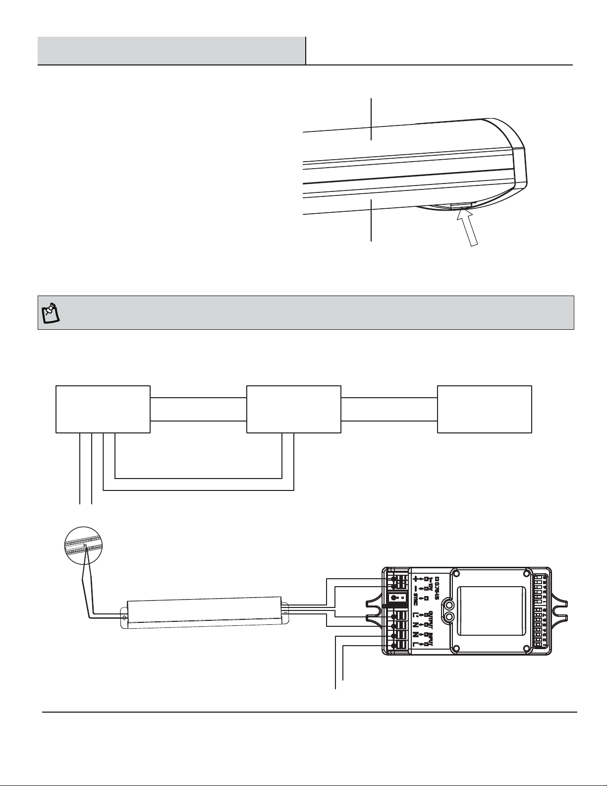
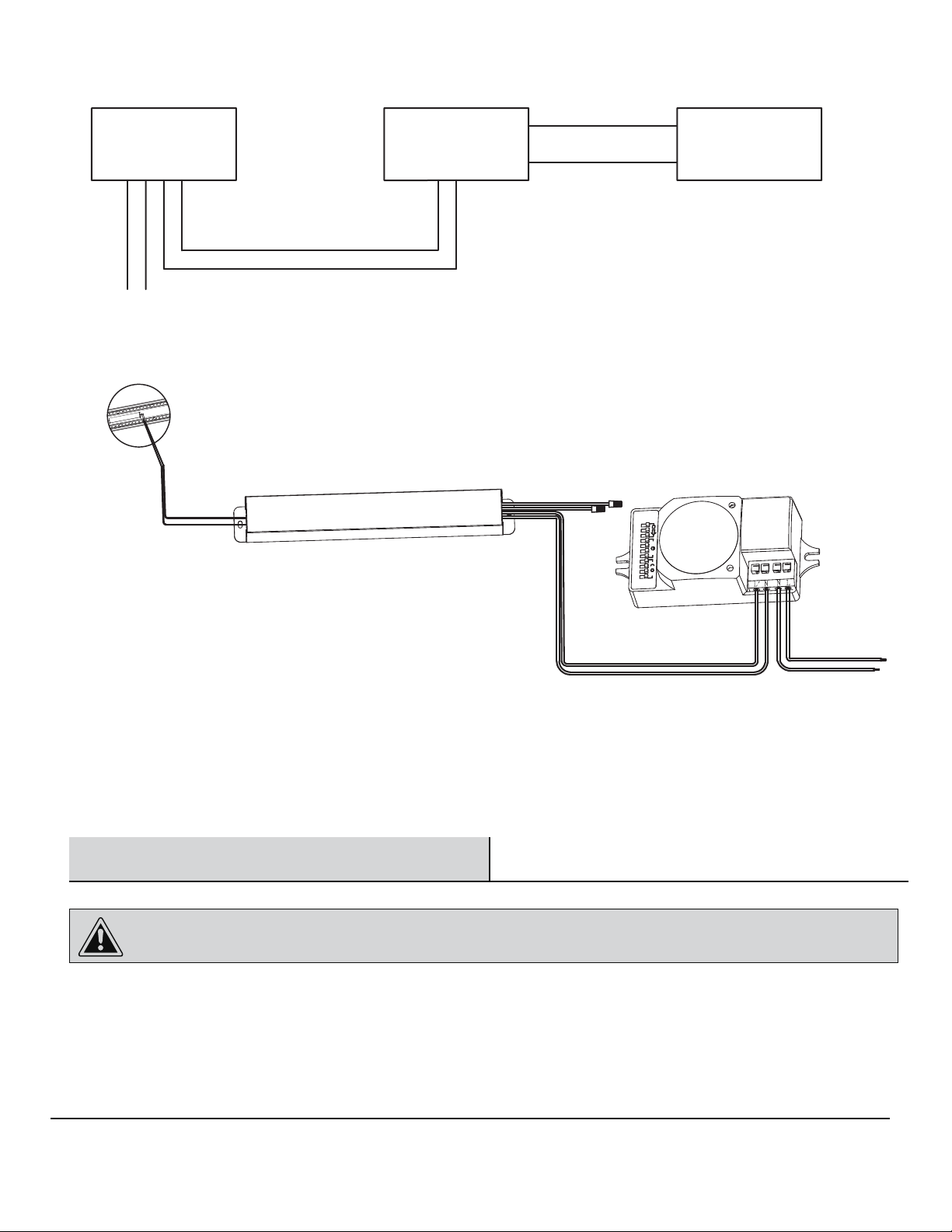
Planning Installation ............................... 3
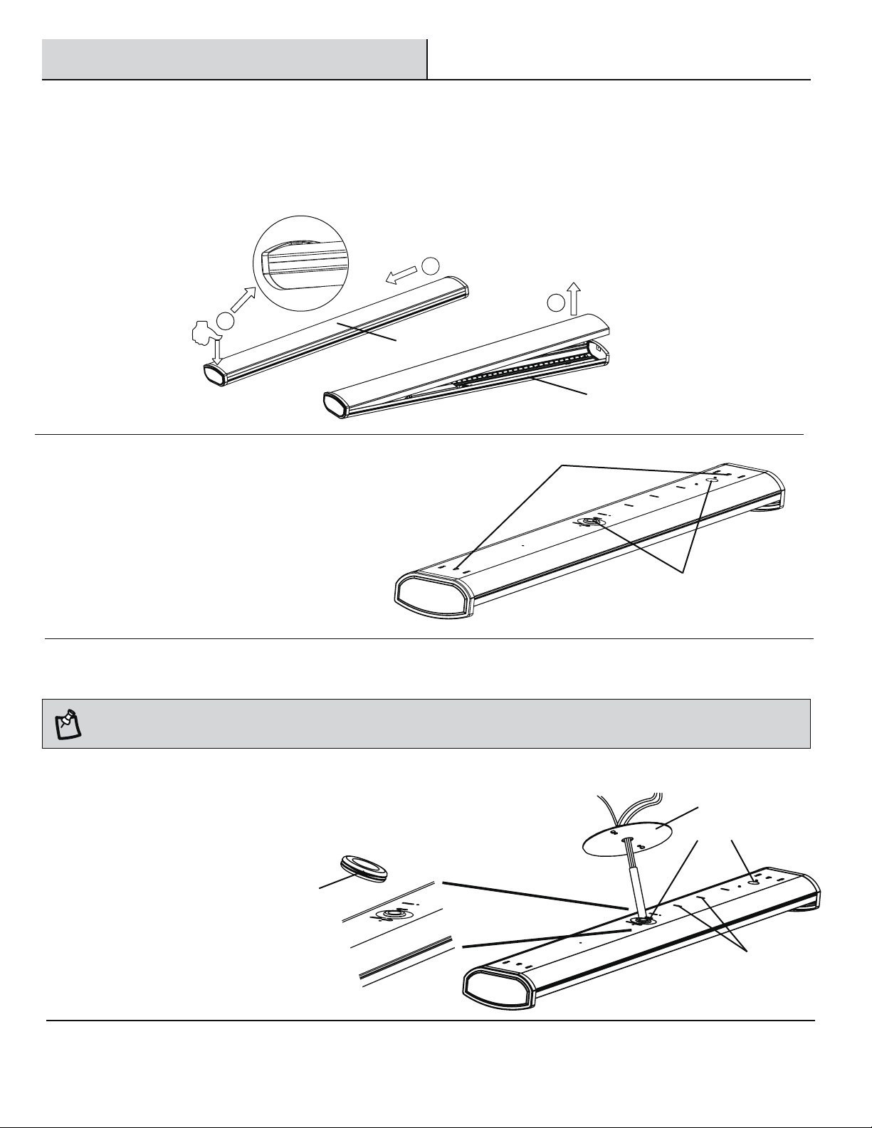
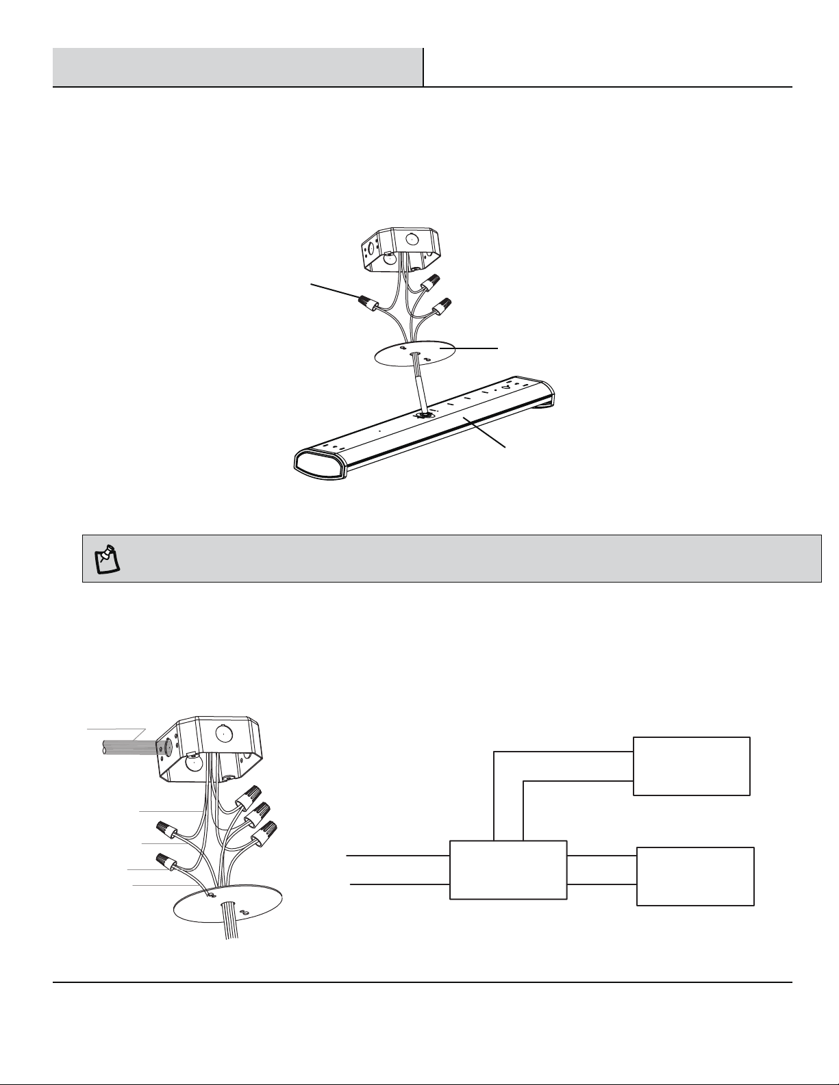
Installation ........................................ 5
Installation (continued).............................6-8
Care and Cleaning ..................................9
Safety Information
WARNING: Carefully read and understand the information
given in this manual before beginning the assembly and
installation. Failure to do so so could lead to electric shock,
fire, or other injuries which could be hazardous or even fatal.
WARNING: Ensure the electricity to the wires you are
working on is shut off. Either remove the fuse or turn off the
circuit breaker.
WARNING: Changes or modifications not expressly approved
by the party responsible for compliance could void the user’s
authority to operate the equipment.
NOTICE: This equipment has been tested and found to comply with the
limits for a Class B digital device, pursuant to Part 15B of the FCC Rules.
These limits are designed to provide reasonable protection against harmful
interference in a residential installation.
This equipment generates, uses and can radiate radio frequency energy
and, if not installed and used in accordance with the instructions, may
cause harmful interference to radio communications.
However, there is no guarantee that interference will not occur in a
particular installation. If this equipment does cause harmful interference
to radio or television reception, which can be determined by turning
the equipment off and on, the user is encouraged to try to correct the
interference by one or more of the following measures:
□Reorient or relocate the receiving antenna.
□Increase the separation between the equipment and the receiver.
□Connect the equipment into an outlet on a circuit different from that to
which the receiver is connected.
□Consult the dealer or an experienced radio/TV technician for help.
Warranty
This product is warranted for a period of 5 years from the date of original purchase against defects in materials and workmanship. If this
product should fail to operate due to defects in material or workmanship within 60 months of purchase, see www.ETiSSL.com for details.
This product will be repaired or replaced, at ETi’s option. This warranty is expressly limited to repair or replacement of product, and liability
for direct, incidental, or consequential damages is hereby expressly excluded. Some states do not allow exclusions of direct, incidental or
consequential damages, so the above limitation of exclusion may not apply to you. This warranty gives the consumer specifc legal rights,
which vary from state to state. WARRANTY IS VOID IF PRODUCT IS NOT USED FOR THE PURPOSE WHICH THIS PRODUCT IS MANUFACTURED.
Package Contents ................................. 4
Hardware Included................................. 4
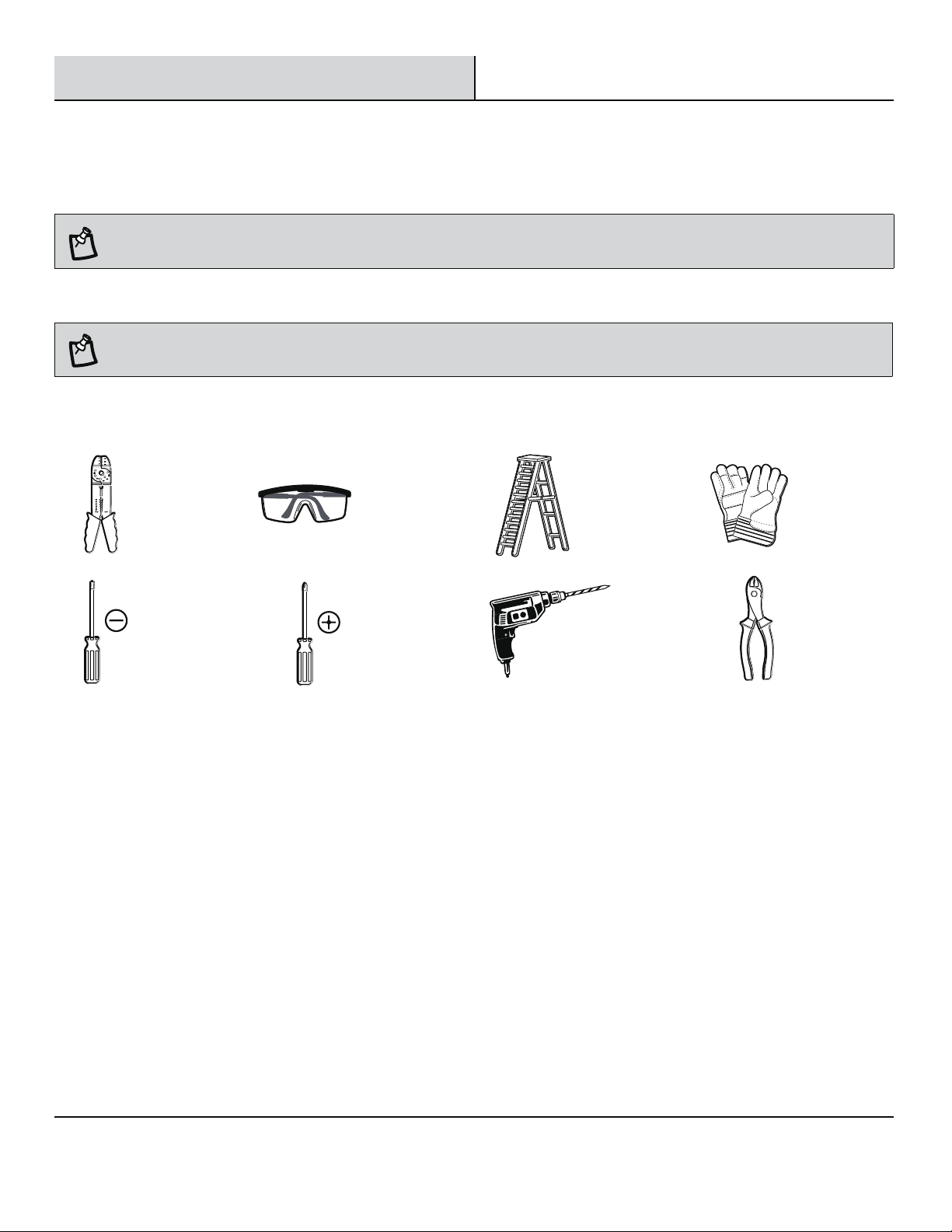
Tools Required .................................... 3

3
Please contact 1-855-384-7754 or further assistance.
If you are unfamiliar with electrical installations, we recommend you contact a qualified electrician to do the installation.
Pre-Installation
PLANNING INSTALLATION
Before beginning assembly, installation or operation of product, make sure all parts are present. Compare parts with the package
contents list. If any part is missing or damaged, do not attempt to assemble, install or operate the product. Contact customer service
for replacement parts.
NOTE: Keep your receipt and these instructions for proof of purchase.
TOOLS REQUIRED
Wire Strippers Safety
Goggles Ladder Gloves
Flathead
Screwdriver
Phillips
Screwdriver
Power Drill
with drill bits
Wire
Cutters
NOTE: Two people are recommended for the installation of this light fixture.
www.ETiSSL.com

4
PACKAGE CONTENTS
Part Description Quantity
A LED Wrap Light Housing 1
B LED Wrap Light Diffuser 1
B
Part Description Quantity
AA Mounting Bracket 1
BB Gasket 1
CC Single Wire Connector 5
DD Electrical Box Screw 2
EE Drywall Anchor 2
FF Mounting Screw 2
HARDWARE INCLUDED
AA
NOTE: Hardware not shown to actual size.
Pre-Installation (continued)
A
BB CC
DD EE FF
WARNING: RISK OF ELECTRIC SHOCK. Ensure the electricity to the wires you are working on is shut off. Either remove the fuse or turn off the
circuit breaker before removing the existing light fixture or installing the new one.
Installation
Select a suitable location that can support the weight of the fixture. Determine the method of mounting before drilling.
With power disconnected to your electrical box, remove the existing fixture. Make a sketch of how the current fixture is wired (by wire
color) or mark the wires with masking tape and a pencil so you will know how to properly reconnect the wires to the new LED light fixture.

5
Please contact 1-855-384-7754 or further assistance.
1 Separating the diffuser from the housing
□Press down gently on one end of the diffuser (B) until you meet with resistance from the bottom of the end cap of the housing (A).
□Slide the diffuser (B) toward the end being pressed down.
□Lift the diffuser (B) from the other end, removing it from the housing (A).
2 Marking the mounting location
□With help from another person, temporarily
hold the fixture housing (A) up to the ceiling to
determine the best mounting position and which
knockout hole to use for wiring the fixture.
□Mark two keyhole locations for mounting.
Installation (continued)
1
2
3
2
2
2
B
Keyholes
A
Knock out holes
□Feed the electrical connection wires through any knock
out hole and then through the mounting bracket (AA). The
connection wires can be held in place by the metal tabs,
if needed.
3 Feeding the wires
NOTE: Put the gasket (BB) on any knock out hole of the fixture to better protect the wires.
AA
BB
Metal tabs
Knock out holes
www.ETiSSL.com

6
Installation (continued)
4 Connecting the wires
□Connect the hot and neutral (black and white) wires from the housing (A) to the same color wires from the electrical box.
□Cover the wire connection using the single wire connector (CC).
□Connect the green wire from the housing (A) to the grounding wire from the electrical box. Secure together using
a single wire connector (CC).
A
To ballasts
Purple(+)
Black(+)
White(-)
Green(E)
Anode(+)
Gray(-)
Cathode(-)
Connect theblackwire and wireL together.
Connect thewhite wireand wireN together.
Connect thegreen wire and earth wire together.
Connect thepurple wire and the anode of the dimmer, and connect thegray wireand the cathode of the dimmer.
Finally, fixall of them with single wire connector (CC).
□
□
□
□
□
Dimmer
0-10V
-
LED Power (DRIVER)
DIM+
DIM+
DIM-
LED lamp panel
LED+
LED-
N
L
CC
AA
NOTE: Please refer to below wire and curcuit diagram if end user has demand for the 0-10V dimmer installation.

7
Please contact 1-855-384-7754 or further assistance.
Installation (continued)
5 Attaching the housing to the ceiling
□Drill a 1/8 in. pilot hole into the screw locations marked on the ceiling. You can also use an awl or nail to dimple the screw holes.
□Install a drywall anchor (EE) and a mounting screw (FF) in each drilled mounting hole, but do not tighten fully.
□Align the 2 mounting keyholes on the housing (A) with the 2 mounting screws in the ceiling. Once both screw heads are through the
large ends of the keyholes, slide the housing until the heads of the screws slide into the narrow ends of the keyholes.
□Finish tightening the mounting screws (FF) until the fixture housing (A) is tightly secured to the mounting surface.
NOTE: The drywall anchors (EE) are only to be used for mounting the fixture onto plaster or drywall surfaces.
FF
GG
A
AA
6Connecting the dimmer wire to the light dimming wire
□
□
□
www.ETiSSL.com
Connect theanode wire of dimmer to the anode wire
of the dimming driver .
Connect thecathode wire of dimmer to the cathode
wire of the dimming driver .
Fixall of them with single wire connector (CC).
Anode (+)
Cathode (-)
RED
BLUE
Single Wire Connector
Wall Box
Dimmer
To Ballast

8
When the sensor is 0-10V step-dimming with LED power supply, circuit wiring diagram is as below.□
0-10V LED Power (DRIVER)
drive+
drive-
DIM+
DIM-
DIM+
DIM-
N
N
L’
L
N
L
Step-dimming
Motion Sensor LED lamp panel
LED+
LED-
NOTE: This wrap light is compatible for motion sensor, and below circuit wiring diagram is for two types of motion sensor. For the sensor, we
suggest to use ETI SSL brand model: 90600145 (ON/OFF) and 90600144 (0-10V).
7Attaching the diffuser to the housing
□Insert one end of the diffuser (B) into the
end cap of the housing (A) to the bottom of
the limit part.
□Push the other end of the diffuser (B) to the
top of the limit part on the opposite end cap.
□Restore power to the electrical box. Turn on
the light switch to activate the fixture.
B
A
Limit part
Installation (continued)
LED+ (RED)
LED+ (BLACK) 0-10V
Motion Sensor
L’ (Black)
L (Black)
N (White)
N (White)
LED DRIVER
B+ (Anode)
B- (Cathode)

9 www.ETiSSL.com
Please contact 1-855-384-7754 or further assistance.
Care and Cleaning
CAUTION: Before attempting to clean the fixture, disconnect the power to the fixture by turning the breaker off or removing the fuse from
the fuse box.
□Clean the fixture with a soft, dry cloth.
□Do not use cleaners with chemicals, solvents, or harsh abrasives.
□Do not use liquid cleaner on the LEDs, LED driver, or wiring inside the light fixture.
When the sensor is ON/OFF (also plus LED power supply), circuit wiring diagram is as below.□
N L’
N
L
NL
Motion Sensor
(ON/OFF)LED Power (DRIVER)
drive+
drive-
DIM+
DIM-
LED lamp panel
LED+
LED-
LED+ (RED)
LED+ (BLACK)
L’ (Black) L (Black)
N (White) N (White)
(ON/OFF)
Motion Sensor
LED DRIVER
B+ (Anode)
B- (Cathode)

Questions, problems, missing parts?
Call ETi SSL Customer Service
9 a.m. – 5 p.m., EST, Monday - Friday
1-855-ETI-SSLI (1-855-384-7754)
Retain this manual for future use.
www.ETiSSL.com

Modéle #
54655441
54676241
Partie #
WR-2-20-940-MV-D
WR-4-40-940-MV-D
GUIDE D’UTILISATION ET D’ENTRETIEN
LUMINAIRE ENVELOPPANT À DEL AVEC 60CM/122 CM
Questions, difficultés, pièces manquantes?
Téléphonez au service à la clientèle de ETi SSL Customer Service
9 a.m. – 5 p.m., HNE, du lundi au vendredi,
1-855-ETI-SSLI (1-855-384-7754)
MERCI
continuellement à créer des produits de qualité visant à améliorer le décor de votre foyer. Consultez notre gamme complète de produits
pour vos projets de rénovation au foyer. Nous vous remercions d’avoir choisi ETi!
www.ETiSSL.com

12
Table des matières
Table des matières ................................. 12
Consignes de sécurité .............................. 12
Garantie.......................................... 12
Avant l’installation ................................. 13
Planification de l’installation ........................ 13
Outils requis..................................... 13
Contenu de l’emballage............................ 14
Quincaillerie fournie............................... 14
Installation ....................................... 15
Installation (suite) ................................
16-18
Entretien et nettoyage .............................. 19
Consignes de sécurité
AVERTISSEMENT : Lisez et comprenez bien les
renseignements fournis dans ce manuel avant de procéder à
l’assemblage et à l’installation. Un manque à le faire pourrait
mener à un risque de choc électrique, d’incendie ou de
blessures qui pourraient être graves, voire même mortelles.
AVERTISSEMENT : Assurez-vous de couper le courant au
circuit sur lequel vous travaillerez. Enlevez le fusible ou coupez
le disjoncteur.
AVERTISSEMENT : Tout changement ou toute modification
non expressément approuvée par la partie responsable de la
conformité peut rendre nulle l’autorisation de l’utilisateur
d’utiliser l’équipement.
AVIS: Ce dispositif a été testé et se trouve en deça des limites pour
un dispositif numérique de Classe B aux termes de la section 15B
des règlements de la FCC. Ces limites servent à offrir une protection
raisonnable contre une interference nocive dans une installation
résidentielle.
Ce dispositif génère, utilise et peut irradier une énergie de fréquence
radio; s’il n’est pas installé et utilisé conformément aux directives, il peut
causer une interférence nocive aux communications radio. Il n’est toutefois
pas garanti qu’aucune interférence ne surviendra dans une installation
particulière. Si le dispositif cause une interférence nuisible à la réception
radio ou télé, ce qui peut être établi en éteignant et rallumant le dispositif,
on conseille à l’utilisateur de tenter de remédier à la situation en utilisant
□Réorienter ou déplacer l’antenne réceptrice.
□Augmenter la distance entre le dispositif et le poste récepteur.
□Brancher l’équipement dans une prise de courant sur un circuit autre
que celui sur lequel le récepteur est branché.
□Demander conseil auprès du marchand ou d’un technicien en radio/télé.
Garantie
Ce produit est garanti contre les vices de matière et de fabrication pour une période de 5 ans à compter de la date d’achat originale. Si le
produit ne fonctionne pas à cause d’unvice de matière ou de fabrication dans les 60 mois suivant son achat, consultez www.ETiSSL.com
pour de plus amples renseignements. Le produit sera réparé ou remplacé, à la discrétion d’ETi. Cette garantie est expressément limitée à
la réparation ou au remplacement du produit et toute responsabilité quant aux dommages directs, indirects ou fortuits est expressément
exclue. Certaines provinces ne permettent pas l’exclusion des dommages directs, indirects ou fortuits et la restriction ci-haut peut ne pas
s’appliquer dans votre cas. Cette garantie accorde au consommateur des droits particuliers qui peuvent varier d’une province à l’autre. LA
GARANTIE EST NULLE ET SANS EFFET SI LE PRODUIT EST UTILISÉ À DES FINS AUTRES QUE CELLES PRÉVUES POUR LE PRODUIT.

13
Si vous avez besoin d’aide, composez le 1-855-384-7754.
Si vous n’êtes pas familier avec les installations électriques, nous recommandons que l’installation soit faite par un électricien qualifié.
Avant l’installation
PLANIFICATION DE L’INSTALLATION
Avant de commencer à assembler ou installer l’article, assurez-vous d’avoir toutes les pièces. Comparez le contenu de l’emballage avec la
nomenclature. S’il y a des pièces manquantes ou endommagées, ne tentez pas d’assembler, d’installer, ni d’utiliser l’article. Communiquez
avec le service à la clientèle pour obtenir des pièces de rechange.
NOTE : Gardez votre facture ainsi que ces instructions comme preuves d’achat.
OUTILS REQUIS
Pince à
dénuder
Lunettes
de sécurité Échelle Gants
Tournevis à
lame plate
Tournevis
à pointe
cruciforme
Perceuse électrique
avec mèche Coupe-fil
NOTE : Nous recommandons que l’installation de ce luminaire soit faite par deux personnes.
www.ETiSSL.com

CONTENU DE L’EMBALLAGE
Pièce Description Quantité
A Boîtier du luminaire enveloppant à DEL 1
B Diffuseur du luminaire enveloppant à DEL 1
Pièce Description Quantité
AA Support de montage 1
BB Joint d’étanchéité 1
CC
DD
Connecteur simple 5
EE
Vis de boîte électrique 2
FF
Ancrage pour placoplâtre 2
Vis de montage 2
QUINCAILLERIE FOURNIE
NOTE : La quincaillerie n’est pas illustrée à sa grandeur réelle.
Avant l’installation (suite)
AVERTISSEMENT : RISQUE DE CHOC ÉLECTRIQUE. Assurez-vous d’avoir coupé le courant aux fils que vous toucherez. Enlevez le fusible ou
déclenchez le disjoncteur du circuit avant d’enlever le luminaire existant ou d’en installer un nouveau.
Installation
Choisissez un endroit convenable où le poids du luminaire peut être supporté. Déterminez le mode de fixation avant de percer des trous.
Une fois le courant coupé à la boîte électrique, enlevez le luminaire existant. Faites une esquisse du câblage du luminaire existant (par
couleur de fil) ou identifiez les fils avec un papier-cache et un crayon; vous saurez ainsi comment reconnecter les fils correctement au
nouveau luminaire à DEL.
14
B
A
AA BB CC
DD EE FF
Un montage de l’installation du boîte de capteur n’est pas incluses; veuillez communiquer avec eti pour achat distinct, s’il vous plaît.

1
2
3
2
2
2
B
Serrures à clé
A
Sortir les trous
AA
BB
15
Si vous avez besoin d’aide, composez le 1-855-384-7754.
1 Séparer le diffuseur du boîtier
□Pressez délicatement sur une extrémité du diffuseur (B) jusqu’à ce que vous sentiez une résistance contre le bas de
l’embout du boîtier (A).
□Poussez le diffuseur (B) vers le point où vous appliquez une pression.
□Soulevez l’autre extrémité du diffuseur (B) puis retirez-le du boîtier (A).
2 Marquer les points de fixation
□Aidé d’une autre personne, tenez temporairement
le boîtier (A) du luminaire contre le plafond pour
établir le meilleur endroit pour l’installation et le
trou à pastille à utiliser pour le câblage.
□Marquez la position des quatre trous oblongs.
□Acheminez les fils électriques dans un des trous à pastille
puis à travers le support de montage (AA). Au besoin, les
fils peuvent être retenus à l’aide des pattes métalliques.
3 Acheminer les fils
NOTE : Placez le joint d’étanchéité (BB) sur le trou à pastille utilisé afin de protéger les fils.
Pattes métalliques
Trous à pastille
Installation
www.ETiSSL.com

16
Installation (suite)
4 Effectuer les connexions
□Connectez le fil chargé et le fil neutre (noir et blanc) du boîtier (A) aux fils de même couleur dans la boîte électrique.
□Exécutez la connexion à l’aide du connecteur double (CC).
□Connectez le fil vert du boîtier (A) au fil de terre de la boîte électrique. Fixez la connexion à l’aide du connecteur simple (DD).
Aux ballasts
Violet(+)
Noir(+)
Blanc(-)
Vert(E)
l'anode(+)
Gris(-)
Cathode(-)
Connectez le fil
Connectez le fil noir et le fil L ensemble.
Connectez le fil blanc et le fil N ensemble.
Connectez le fil vert et le fil de terre ensemble.
Connectez le fil violet et l'anode du gradateur, et connectez le fil gris et la cathode du gradateur.
Enfin, réparez-les tous avec des écrous métalliques (DD).
□
□
□
□
□
Variateur
0-10V
-
LED Puissance (DRIVE)
FAIBLE+
FAIBLE+
FAIBLE-
Panneau de lampe LED
LED+
LED-
N
L
A
CC
AA

17
Si vous avez besoin d’aide, composez le 1-855-384-7754.
Installation (suite)
5 Fixer le boîtier au plafond
□Percez un trou de 3 mm (1/8 po) à chaque position de vis marquée sur le plafond. Vous pouvez aussi utiliser un poinçon ou un
clou pour pointer les trous de vis.
□Posez un ancrage à placoplâtre (FF) et une vis de montage (GG) dans chaque trou de montage, sans serrer la vis à fond.
□Alignez les 4 trous oblongs du boîtier (A) avec les 4 vis de montage au plafond. Une fois la tête des vis introduite dans la grande
ouverture des trous oblongs, faites glisser le boîtier pour ancrer la tête des vis dans la partie étroite des trous oblongs.
□Finissez le montage en serrant les vis de montage (GG) de façon à ce que le boîtier (A) repose fermement contre la surface de
montage.
NOTE : Les ancrages pour placoplâtre (FF) ne s’utilisent que pour la fixation sur une surface en plâtre ou placoplâtre.
FF
GG
A
AA
www.ETiSSL.com
6Connecting the dimmer wire to the light dimming wire
□
□
□
Connect theanode wire of dimmer to the anode wire
of the dimming driver .
Connect thecathode wire of dimmer to the cathode
wire of the dimming driver .
Fixall of them with single wire connector (CC).
Anode (+)
Cathode (-)
RED
BLUE
Single Wire Connector
Wall Box
Dimmer
To Ballast

18
Installation (suite)
7 Poser le diffuseur sur le boîtier
□Introduisez une extrémité du diffuseur (A) dans
l’embout du boîtier (A) jusqu’au fond du butoir.
□Poussez l’autre extrémité du diffuseur (B) dans le
haut du butoir de l’embout opposé.
□Remettez le circuit sous tension. Actionnez
l’interrupteur pour allumer le luminaire.
B
A
Butoir
Quand le capteur est 0-10V step-dimming avec alimentation LED appuyant, le schéma de câblage du circuit est comme ci-dessous.□
0-10V LED Puissance (DRIVER)
conduire+
conduire-
FAIBLE+
FAIBLE-
FAIBLE+
FAIBLE-
N
N
L’
L
N
L
Le capteur
(CAPTEUR) LED Panneau de lampe
LED+
LED-
NOTE: Remarque: cette lampe est compatible pour le capteur mouvement à step-dimming, et le schéma de câblage ci-dessous est destiné à
deux types de capteurs mouvement.
Pour le capteur, Nous suggérons d'utiliser le modèle de marque ETI SSL: 90600145 (commutateur) et 90600144 (0-10V).
LED+ (RED)
LED+ (BLACK) 0-10V
L’ (Black)
L (Black)
N (White)
N (White)
LED DRIVER Motion Sensor
B+ (Anode)
B- (Cathode)

19
Si vous avez besoin d’aide, composez le 1-855-384-7754.
Entretien et nettoyage
MISE EN GARDE : Avant le nettoyage, coupez l’alimentation au luminaire en plaçant le disjoncteur en position hors tension ou en
enlevant le fusible de la boîte à fusibles.
□Nettoyer le luminaire à l’aide d’un linge doux et sec.
□N’utilisez pas de nettoyants contenant des produits chimiques, des solvants ou des produits abrasifs forts.
□N’utilisez pas de nettoyant liquide sur la DEL, le transformateur ou les fils à l’intérieur du luminaire.
Quand le capteur est le type de commutateur (aussi l'alimentation LED appuyant), le schéma de câblage du circuit est comme ci-dessous.□
LED Puissance (DRIVER)
N L’
N
L
NL
Le capteur
(CAPTEUR)
(Type de commutateur) conduire+
conduire-
FAIBLE+
FAIBLE-
LED Panneau de lampe
LED+
LED-
www.ETiSSL.com
LED+ (RED)
LED+ (BLACK)
L’ (Black) L (Black)
N (White) N (White)
(ON/OFF)
Motion Sensor
LED DRIVER
B+ (Anode)
B- (Cathode)

Questions, difficultés, pièces manquantes?
Téléphonez au service à la clientèle de ETi SSL Customer Service
9 a.m. – 5 p.m., HNE, du lundi au vendredi,
1-855-ETI-SSLI (1-855-384-7754)
Conservez ce manuel pour référence ultérieure
www.ETiSSL.com
This manual suits for next models
3
Table of contents
Languages:
Other ETI Solid State Lighting Light Fixture manuals
Popular Light Fixture manuals by other brands

Philips
Philips Lightolier Lytespan 9100 specification

TECshow
TECshow NEBULA FX 3-in-1 user manual

Philips
Philips SL111A2 specification

Luxillo
Luxillo LED-String-Downlight instruction manual

Larson Electronics
Larson Electronics GAU-HB-12L-LED-WP-WCM instruction manual

ARRI
ARRI Claypaky AXCOR PROFILE 400 instruction manual

Philips
Philips 31607-48-16 user manual

Cooper Lighting
Cooper Lighting Combo Trimless Series LV-116-TR installation instructions

Lightolier
Lightolier Calculite 8081 specification

Lightolier
Lightolier H9S2GLR132 specification

venalsol
venalsol AGRO-O instructions

Lightolier
Lightolier Lytecaster 1134 specification