ETI CTE Series User manual

ETI, d.o.o.,Obrezija 5 ETI Polam Sp. z o.o. V.05.18
SI-1411 Izlake ul.Jana Pawła II 18 tel .+48 (23) 691 93 00
http://etigroup.eu/products-services 06-100 Pułtusk fax.+48 (23) 691 93 60
1/4
CTE- TOROIDAL CURRENT TRANSFORMERS / Manual instruction
Toroidalne przekładniki prądowe / Instrukcja obsługi
GENERALITY/ INFORMACJE OGÓLNE
The toroidal current transformer CTE line allow the remark of homopolar differential
current disperse in the earth direction. The toroidal current transformer CTE are designed to be
combined with relays of maximum differential current LRE line.
The current transformer must be installed at the beginning of line or load to protect or to supervise,
all the active conductor (phase and neutral) of the single phase and three phase line. The current
transformer read the vectorial sum of the current in the way to transmit at the secondary coil the earth
leakage current.
For other applications of current transformer CTE it’s necessary to see specific documentation (for
example the reading of the earth homopolar current on supplying transformer).
Toroidalne przekładniki prądowe CTE.. umożliwiająwykrycie homopolarnych prądów
różnicowych spływających w kierunku ziemi. Przekładniki sązaprojektowane do współpracy z
przekaźnikami różnicowoprądowymi serii LRE…
Przekładnik prądowy musi byćzainstalowany na początku linii lub obciążenia dla ochrony lub
nadzoru wszystkich czynnych przewodów (fazowych i neutralnego) w sieci jedno- lub trójfazowej.
Przekładnik odczytuje wektorowąsumęprądów w celu przeniesienia na uzwojenie wtórne cewki
sygnału odpowiadającego prądowi upływu.
Dla prawidłowego zastosowania przekładnika CTE… należy zapoznaćsięze specyfikązjawisk
obejmujących wykrywanie prądów różnicowych.
INTRODUCTION/ WSTĘP
The current transformer CTE are built with a core of sheet iron of excellent magnetic
quality that allows to read fault currents a lot of low. On the core are wrapped two coils, one to read
the fault signal, the other to make a test of functionality.
Using specific models of relays it’s possible to do the test that use this second coil, the differential relay give a signal at the test coil, this signal creates a flow like that of a
failure, that the first coil notice and it send at the relay that tripped.
The choice of the toroidal current transformer depends by the dimensions of the conductors or the bar that must pass inside. It’s possible to install a current transformer without
to disconnect the cable of wiring, using the models with the core that can be opened./
Przekładniki prądowe CTE… sązbudowane na rdzeniu z blach stalowych o dobrej przenikalności magnetycznej umożliwiającej odczyt prądów o bardzo małej
wartości. Na rdzeniu nawinięte sa dwa uzwojenia, jedno dla odczytu sygnału pochodzącego od prądu różnicowego zaśdrugie umożliwiające test funkcjonalny.
Wykorzystując specyficzne modele przekaźników różnicowoprądowych możliwe jest wykonanie testu, wykorzystującego drugie uzwojenie, poprzez które przekaźnik różnicowy
podaje sygnał na uzwojenie testowe, który to sygnał tworzy przepływ prądu podobnego do tego jaki powstaje przy wykryciu rzeczywistego upływu w sieci. Sygnał ten zostaje
wykryty przez uzwojenie pomiarowe i powoduje zadziałanie przekaźnika.
Wybór przekładnika toroidalnego zależy od rozmiarów przewodu lub szyn które musząprzechodzićprzez jego otwór. Możliwe jest zainstalowanie przekładnika prądowego bez
potrzeby rozłączania kabla głównego, z wykorzystaniem wykonańz dzielonym rdzeniem.
TYPES/ TYPY
Toroidal currant transformer/ Toroidalny przekładnik prądowy
Type/typ code No/ nr kod. Description/opis weight [g] packing [pcs]
CTE-35 004671609 Current transformer/przekładnik prądowy 200 1
CTE-60 004671610 Current transformer/przekładnik prądowy
260 1
CTE-80 004671611 Current transformer/przekładnik prądowy
400 1
CTE-110 004671612 Current transformer/przekładnik prądowy
450 1
CTE-160 004671613 Current transformer/przekładnik prądowy
980 1
CTE-210 004671614 Current transformer/przekładnik prądowy
1200 1
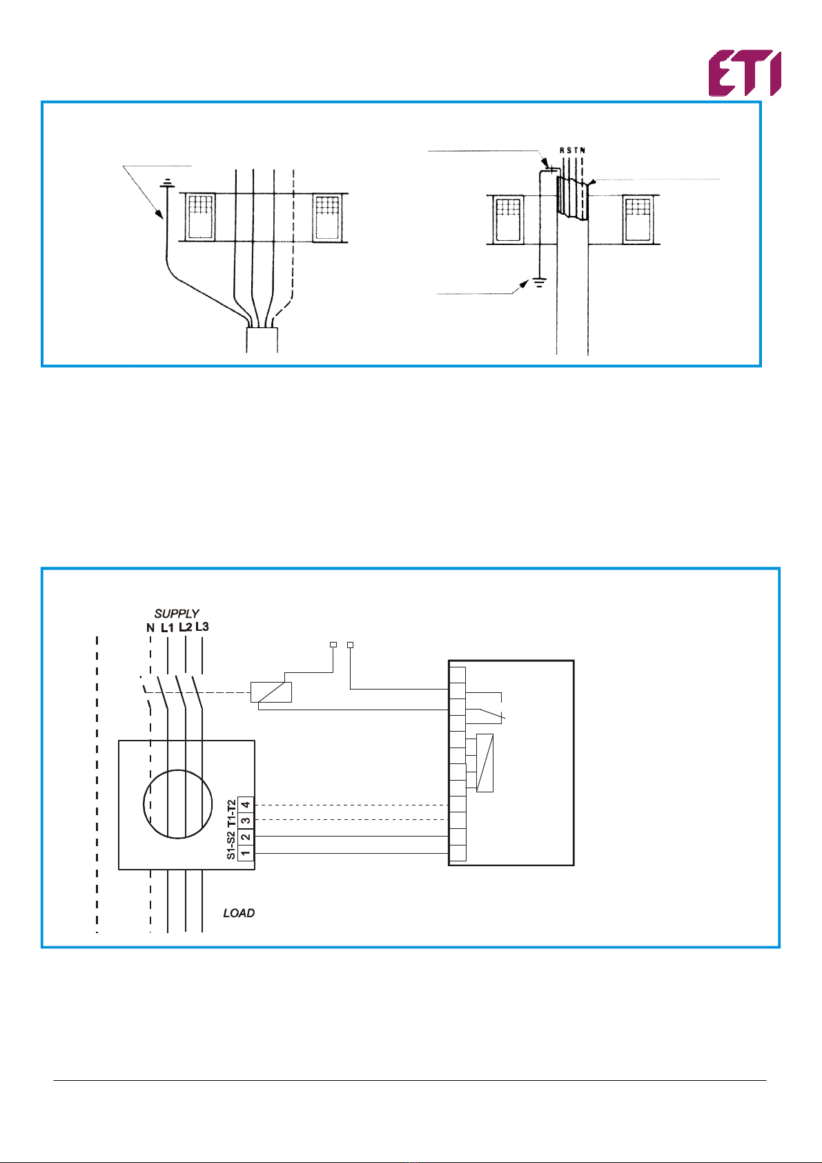
INSTALATION/ INSTALACJA
The toroidal current transformers must be installed in the way that all the conductors of the line (phase and neutral if distribute) pass inside. The earth conductors,
instead, must not pass inside. The direction of the passage must be the same for all the conductors and in the application where the current transformer in parallel are not used,
it’s not necessary to respect the sense of the introduction (P1). From the 1 (S1) and 2 (S2) terminals must be taken the signal of output to connect ad the differential relay for
the measure, the 3-4 terminals must be connected at the output test of the relay that have this option; at contrary they must be disconnected.
It’s better to use conductor twisted or shielded for this connection, and possibly far from cable of power. The minimum section of the wire of the connection should
have a maximum resistance of 3 Ω; approximately it’s possible to take a section of 0,5 mm2max 20 meters and of 2,5 mm2max 100 meters.
The fixing of the current transformer can be done on the bottom of the electric panel, on section or on cable. For the current transformer tha can be opened it’s necessary to
verify that the contact surface of the two half-core is cleaned, the correct closing of the bolts and the connection of the cable that join the two parts. If present, the shield, must
be connected at earth after toroidal current transformer or if the shield pass inside, the connection at earth of the shield must pass another time in opposite sense inside the
toroidal current transformer (see the figure). In presence of specific over current, at the starting of big motor, the transformer are turned on, that can cause the tripping untimely
of differential relays, it’s necessary to observe the following indications: to install a current transformer on a stretch rectilinear cable, to centre the positioning of the
cable inside the toroidal current transformer, to use current transformer bigger than the necessary (also 2 time of diameter of cables)./
Przekładniki toroidalne musząbyćinstalowane w taki sposób aby obejmowały wszystkie przewody linii (fazowe i neutralny – jeśli występuje). Przewody uziemiające
z kolei nie mogąprzechodzićprzez otwór przekładnika. Kierunek przejścia musi byćzgodny dla wszystkich przewodów zaśw aplikacjach gdzie nie występująrównolegle
podłączone przekładniki prądowe, nie jest konieczne zachowanie kierunku wprowadzenia (P1).
Z zacisków 1 (S1) i 2 (S2) musi byćpobrany sygnał wyjściowy do podłączenia na wejście pomiarowe przekaźnika różnicowoprądowego, natomiast zaciski 3-4 musząbyć
podłączone na wyjście testowe przekaźnika, o ile jest on wyposażony w takąopcję. W przeciwnym wypadku zaciski te należy pozostawićniepodłączone.
Zaleca sięstosowanie skrętki przewodowej lub przewodu ekranowanego oraz prowadzenie go z dala od przewodów silnoprądowych. Minimalny przekrój powinien
zapewniaćrezystancje przewodu nie większąniż3 Ω; co przy przekroju 0,5 mm2daje max 20 metrów zaśprzy przekroju 2,5 mm2max 100 metrów.
Jeśli występuje ekran, musi on byćpołączony z przewodem uziemiającym za przekładnikiem a jeśli przechodzi on przez otwór przekładnika, połączenie uziemiające musi
przejść powrotnie przez otwór (patrz rysunek). W niektórych sytuacjach dużych przeciążeń, np. przy rozruchu dużych silników, załączaniu transformatorów itp. co może
spowodowaćprzedwczesne zadziałanie przekaźnika różnicowego, należy przestrzegaćnastępujących wskazówek:
zainstalowaćprzekładnik prądowy na prostoliniowym odcinku kabla i wycentrowaćkabel wewnątrz przekładnika prądowego lub zastosowaćprzekładnik większy
niżjest to konieczne (nawet 2 razy większy od średnicy kabla).
ETI, d.o.o.,Obrezija 5 ETI Polam Sp. z o.o. V.05.18
SI-1411 Izlake ul.Jana Pawła II 18 tel .+48 (23) 691 93 00
http://etigroup.eu/products-services 06-100 Pułtusk fax.+48 (23) 691 93 60
2/4
Protection conductor
Shield of the cable
External insulation covering
of the cable
Protection conductor
L1 L2 L3 N
APPLICATIONS/ ZASTOSOWANIE
The typical application of the current transformer is the detecting of the differential current but it’s possible to use it to the detecting the leakage current in particular
application, like: parallel lines, section lines, detecting the leakage current on the connection neutral / earth of the transformer or by line current transformers, the last used when
the largest current transformer is not capable to contain all the conductors.
To use this current transformers serie with instruments different from LRE series differential relays, the maximum load must be 600Ω.
For information concerning this application please contact our technical support./
Typowa aplikacja przekładnika prądowego obejmuje wykrywanie prądów różnicowych ale jest możliwe użycie go do wykrywania prądów upływu w innych aplikacjach
jak np: równoległa praca transformatorów, linie wielosekcyjne, wykrywanie prądu upływu w połączeniu przewodu zerowego/uziemienia transformatora lub przez przekładniki
prądowe linii, ten ostatni przypadek występuje gdy największy przekładnik prądowy nie jest w stanie objąć wszystkich przewodów.
Przy wykorzystaniu tych przekładników toroidalnych z instrumentami innymi niżrodzina przekładników różnicowo-prądowych LRE, maksymalna ich wartość nie może
przekraczać600Ω.
WIRING CONNECTION/ DIAGRAM POŁĄCZEŃ
Aux
Earth
ELR...
CT...
xxx x
current input
test output
(eventually)
Example of diagram of
connession on three-phase
line with ELR relay serie with
switch with opening coil
LRE
DA..
CTE…
Example of connections three-
phase line for LRE relay with
changeover switch to MCCB’s
shunt trip DA../
Przykład schematu podłączeń
linii trójfazowej z zabezpie-
czeniem serii RLE.. oraz
wyzwalaczem wzrostowym
DA..

ETI, d.o.o.,Obrezija 5 ETI Polam Sp. z o.o. V.05.18
SI-1411 Izlake ul.Jana Pawła II 18 tel .+48 (23) 691 93 00
http://etigroup.eu/products-services 06-100 Pułtusk fax.+48 (23) 691 93 60
3/4
DIMENSIONS/ WYMIARY
Type/Typ Dimensions/ Wymiary (mm)
A B C D E F G H K
CTE-35
35 100 60 110 47 50 43 30 -
CTE-60
60 100 60 110 47 50 43 30 -
CTE-80
80 150 110 160 70 50 43 30 -
CTE-110
110 150 110 160 70 50 43 30 -
CTE-160
160 220 156 236 110 64 50 34 -
CTE-210
210 310 240 290 145 260 280 36 55
CTE-35, CTE-60, CTE-80, CTE-110, CTE-160
CTE-210

ETI, d.o.o.,Obrezija 5 ETI Polam Sp. z o.o. V.05.18
SI-1411 Izlake ul.Jana Pawła II 18 tel .+48 (23) 691 93 00
http://etigroup.eu/products-services 06-100 Pułtusk fax.+48 (23) 691 93 60
4/4
TECHNICAL FEATURES/ DANE TECHNICZNE
Type/ Typ
CTE-35
CTE-60
CTE-80
CTE-110
CT-1/160
CT-1/210
Core type /typ rdzenia Closed/
zamknięty
Closed/
zamknięty
Closed/
zamknięty
Closed/
zamknięty
Closed/
zamknięty
Closed/
zamknięty
Useful internal diameter/ użyteczna
średnica wewnętrzna 35 mm 60 mm 80 mm 110 mm 160 mm 210 mm
Weight /waga 0,22 kg 0,28 kg 0,45 kg 0,52 kg 1,35 kg 1,45 kg
Min. measurable current/ min. prąd
mierzony
25 mA 25 mA 100 mA 100 mA 250 mA 250 mA
Mounting position/ pozycja montażu
any one/dowolna
Application/ zastosowanie for the use with ELR series differential relays/ do współpracy z
zabezpieczeniami róznicowoprądowymi serii LRE
Working temperature / temperatura
pracy -10÷70°C
Storing temperature /temp.
składowania -20÷80 °C
Transformation ratio/ przekładnia 500/1
Insulation/ izolacja 2,5 kV for 60 sec.
Permanent overload/ trwałe
przeciążenie 1000A
Thermal over load przeciążenie
termiczne 40kA for/przez 1 sec. /sek.
Terminals/ złacza with screw for cable max 2,5 mm2/
śrubowe dla przewodu max 2,5 mm
2
Protection degree stopieńochrony IP20
Standards/ normy CEI-EN 50081-2 CEI-EN50082-2 bezp. CEI 41.1 CEI-EN 60255
Contact the technical assistance or refer at specific document for application don’t described in this manual./
Dla uzyskania informacji nie opisanych w niniejszej instrukcji prosimy skorzystaćz innych dokumentów lub z naszym
Działem Pomocy Technicznej.
ENVIROMENTAL INFORMATION:
This label indicates that this product should not be disposed of with household waste. It should be deposited at an appropriate facility to enable recovery and
recycling.
INFORMACJE DOTYCZĄCE ŚRODOWISKA:
Etykieta ta oznacza, że tego produkt u nie należy wyrzucaćrazem z odpadami z gospodarstwa domowego. Należy go przekazaćdo odpowiedniego zakładu, gdzie
zostanie poddany odzyskowi i recyklingowi.
NOTE
At reason of the evolution of standards and products, the company reserves to modify in every time the features of the product described in this document, that it’s necessary to
verify preventively.
The liability of the producer for damage caused by defect of the product ”can be reduced or deleted (…) when the damage is caused joint by a defect of product or for blame of
the damaged or a person of which the damaged is responsible” (Article 8, 85/374/CEE).
UWAGA
Firma zastrzega sobie prawo do dokonywania w każdej chwili zmian parametrów wyrobów opisanych w niniejszym dokumencie, dlatego konieczna jest jest uprzednia
weryfikacja jego aktualności.
Odpowiedzialność producenta za szkody spowodowane wadliwościąproduktu ”może byćzmniejszona lub zniesiona (…) gdy szkoda została wywołana łącznie przez wadę
produktu i wskutek jego uszkodzenia lub z winy osoby, która za szkodęjest odpowiedzialna” (Artykuł 8, 85/374/CEE).
This manual suits for next models
6
Other ETI Transformer manuals


