ETIC MR1200 User manual

MR1200
RADIO MODEM 1200 bauds
----------
USER MANUAL
908709-02
(AUGUST 2000)


Table of contents
ETIC - MR1200 - USER MANUAL - 908709-02 Page3
1. INTRODUCTION ..............................................................................................................................5
2. INSTALLATION................................................................................................................................7
2.1. PREAMBLE .........................................................................................................................................7
2.2. EXTERNAL DESCRIPTION ....................................................................................................................7
2.3. CONNECTING TO THE TERMINAL.........................................................................................................8
2.4. CHOICE OF RADIO CHANNEL DATA TRANSMISSION RATE...................................................................9
2.5. POWER SUPPLY CONNECTION .............................................................................................................9
2.6. CONNECTING TO THE TRANSCEIVER ...................................................................................................9
2.6.1. Description of the LF interface signals ......................................................................................9
2.6.2. The type of connecting cable to use..........................................................................................13
2.6.3. Factory pre-setting ...................................................................................................................14
2.6.4. Particularity of the 2400 b/s version ........................................................................................14
2.7. POWER SAVING FEATURE SET UP ......................................................................................................15
2.8. CONNECTING THE OPTIONAL MICROPHONE + LOUDSPEAKER SET .....................................................16
2.8.1. Description of the microphone/loudspeaker interface..............................................................16
2.8.2. PTT connection (push to talk) ..................................................................................................16
2.8.3. Microphone connection............................................................................................................17
2.9. T/R POWER SUPPLY ..........................................................................................................................17
3. CONFIGURATION .........................................................................................................................19
3.1. ENTERING CONFIGURATION MODE ....................................................................................................19
3.2. CONFIGURATION COMMANDS ...........................................................................................................19
3.3. QUICK CONFIGURATION....................................................................................................................20
3.4. OPERATING PARAMETERS AND OPTIONS ...........................................................................................21
3.4.1. Configuring the terminal-modem interface ..............................................................................21
3.4.2. Configuring the radio interface................................................................................................23
3.4.3. Operating parameter................................................................................................................25
3.4.4. Power saving feature................................................................................................................26
3.4.5. Other parameters......................................................................................................................27
3.5. LEAVING CONFIGURATION MODE......................................................................................................28
4. OPERATION....................................................................................................................................29
4.1. PRINCIPLE ........................................................................................................................................29
4.2. RADIO CHANNEL...............................................................................................................................29
4.2.1. Data transmission method........................................................................................................29
4.2.2. Format and coding ...................................................................................................................30
4.2.3. Operating conditions................................................................................................................30
4.3. MODEM CONTROL MODES ................................................................................................................31
4.3.1. The terminal-modem interface..................................................................................................31
4.3.2. Automatic mode........................................................................................................................31
4.3.3. Marked automatic mode...........................................................................................................32
4.3.4. Direct mode ..............................................................................................................................32
4.3.5. V25bis mode .............................................................................................................................33
4.4. RADIO CHANNEL ACCESS, & USE OF THE CCIR/ZVEI TONE DIALLER ..............................................36
4.4.1. Introduction..............................................................................................................................36

Table of contents
Page 4 ETIC - MR1200 - USER MANUAL - 908709-02
4.4.2. Programming............................................................................................................................36
4.4.3. Radio relay control...................................................................................................................37
4.4.4. Usage in a V25bis call command .............................................................................................37
4.5. POWER SUPPLY SAVING (SLEEP MODE) .............................................................................................38
4.5.1. Operation .................................................................................................................................38
4.5.2. Sleep model ..............................................................................................................................38
4.5.3. Transceiver wake up.................................................................................................................38
4.5.4. Power state up..........................................................................................................................39
4.5.5. Configuration mode wake up....................................................................................................39
4.6. SPEECH USE......................................................................................................................................39
Introduction
ETIC - MR1200 - USER MANUAL - 908709-02 Page5
1. INTRODUCTION
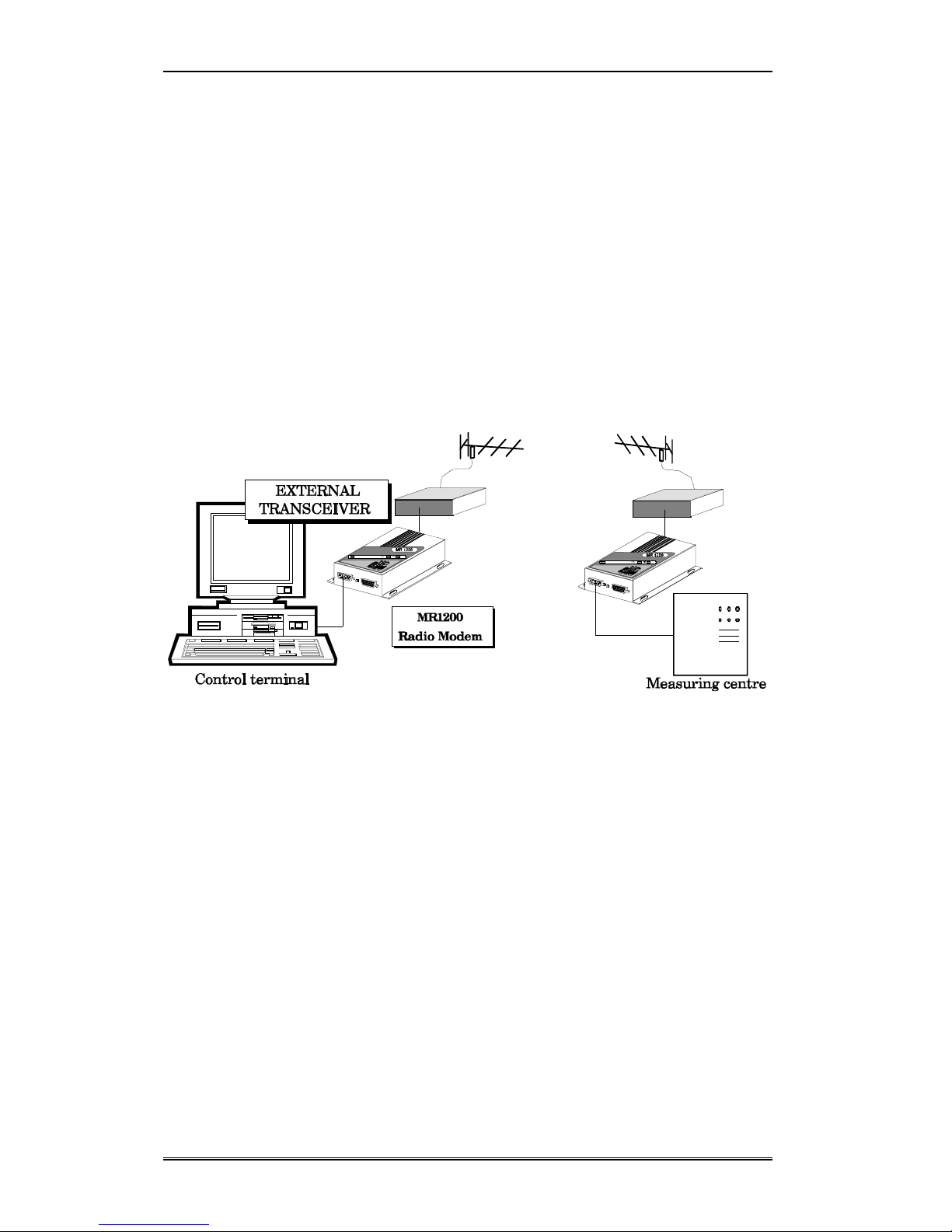
The MR1200 modem is designed for half duplex data communication over a radio-frequency channel.
Connection is made to an external VHF or UHF transceiver.
The MR1200 exists in 2 versions:
- 1200 b/s version.
- 2400 b/s version.
The general features of the MR1200 are :
•Half duplex data transmission : synchronous data transmission using FFSK modulation at
1200 b/s or 2400 b/s, plus data protection using an error correction code.
•
RS232 or RS485 serial link to the Data Terminal Equipment, with a choice of command modes
including 3-wire "automatic" mode (TxD, RxD, ground) in RS232 mode.
•15-way sub-D connector for connection to the external transceiver .
•Radio channel access conflict management : multiple equipment using the same radio
channel.
•Microphone/loudspeaker set - optional.
•Possibility exists to selectively address a radio relay conforming to CCIR or ZVEI standards.

Introduction
Page 6 ETIC - MR1200 - USER MANUAL - 908709-02
•Minimal power consumption of 50 mA, reduced to 300 µA using the power saving feature.
•Durable and compact case housing the data handling/interface card.
•Completely configurable from an ASCII terminal, using an elementary set of commands.

Installation
ETIC - MR1200 - USER MANUAL - 908709-02 Page7
2. INSTALLATION
2.1. Preamble
The MR1200 has an IP40 protection index. For outdoor installation therefore it will be necessary to
site the modem, transceiver, Data Terminal Equipment, battery and any temperature regulating devices
in a clean, dry enclosure.
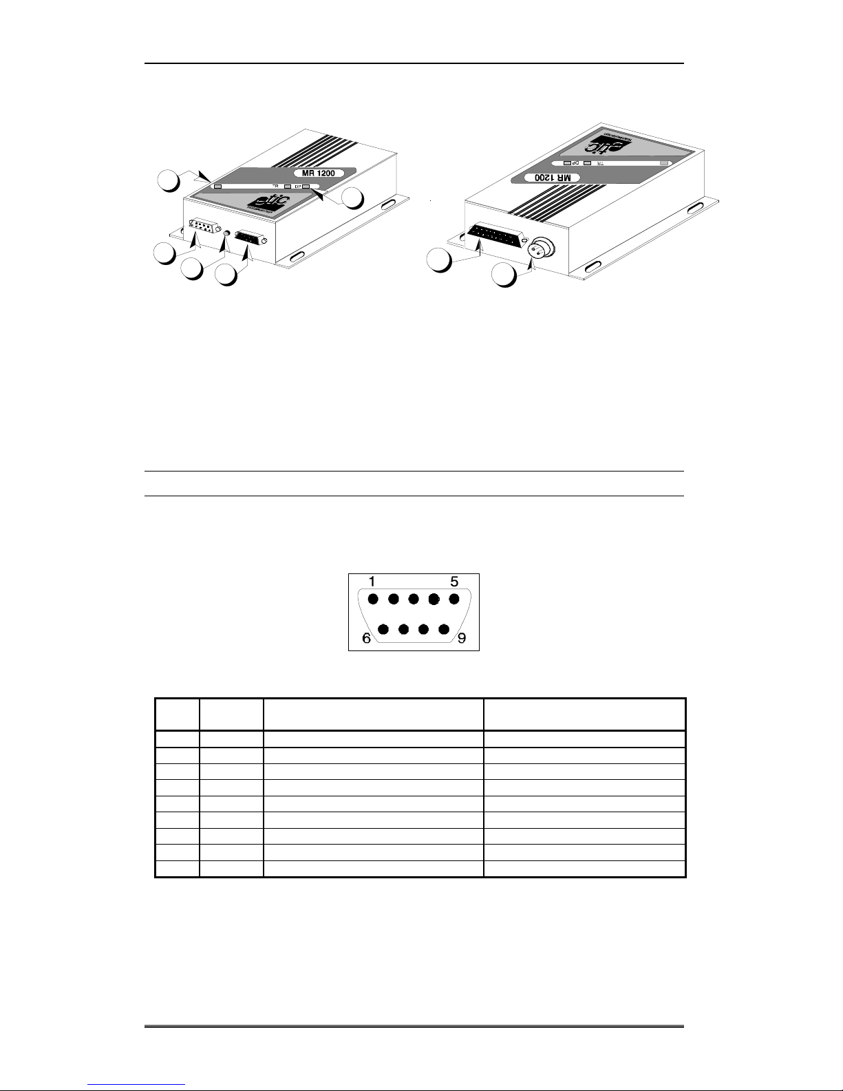
2.2. External description
The MR1200 modem is housed in a metal box.
Dimensions: 180 x 130 x 45 (L x W x H)
Overall weight : 550 g
Impact and penetration : IP40
Fixing centres :
150 mm
120 mm
Installation
Page 8 ETIC - MR1200 - USER MANUAL - 908709-02
1 : Serial connector to data terminal (male 9-way sub-D).
2 : Miniature push-button switch to enter configuration mode.
3 : RS485 serial link or Microphone / loudspeaker connector, optional
(reference MIC-02)
4: Power indicator.
5 : Radio transmission (TR) and reception (DP) indicators.
6 : External transceiver connector (female 15-way sub-D).
7 : Power connector (10 to 16 Volts).
2.3. Connecting to the terminal
The MR1200 dialogues with its command terminal over an RS232 (+12V/ -12V) serial link. The
connector used is a male, 9-way sub-D whose pinout is as shown :
The different circuits carried on the interface are shown in the following table :
Pin Circuit Function Usage according to control mode
automatic direct V25bis
1 109-DCD Detection of modulated carrier optional optional optional
2 104-RxD Data reception yes yes yes
3 103-TxD Data transmission yes yes yes
4 108/2-DTR Wake-up / V25bis dialogue optional optional yes
5 102-SG Signal ground yes yes yes
6 107-DSR Radio communication underway optional advised yes
7 105-RTS Send command - in direct mode - yes -
8 106-CTS Clear to send (flow control) advised yes yes
9 125-RI Received call indicator - V25bis mode optional optional optional
Remarks :
•The command data terminal can be any type as long as its serial interface can function with the
following speeds and transmission formats :
1
23
4
5
6
7

Installation
ETIC - MR1200 - USER MANUAL - 908709-02 Page 9
speed : 150, 300, 600, 1200, 2400, 4800 or 9600 bits/s
format : 7E1, 7O1, 7-2, 7E2, 7O2, 8-1, 8E1, 8O1, or 8-2
•In practice, RS232 cables should be no longer than 15 metres. If the installation is exposed to
electrical or radio disturbance reduce cable lengths to a minimum.
2.4. Choice of radio channel data transmission rate
As standard, the modem uses a 1200 baud radio channel data rate. It can also be factory configured to
work at 2400 baud.
2.5. Power supply connection
The MR1200 needs a d.c. power supply voltage of between 10.6 V et 15.8 V. When used on an
isolated site a 12V lead battery is an ideal solution.
The MR1200 is fitted with a circular, male, power supply connector whose pinout is as shown :
1 : +12 V
2 : ground
3: not connected
Remarks :
•The MR1200 does not possess an ON/OFF switch.
•The MR1200 works from a single source of power. Where two power sources are used (battery
+ solar panels, for example), switching between them must be done externally.
2.6. Connecting to the transceiver
The MR1200 has been designed to be connected to different types of VHF or UHF transceivers (T/R).
Connecting to a T/R does, however, require level adjustments to be carried out, and sometimes changes
to be made to the circuit board.
2.6.1. Description of the LF interface signals
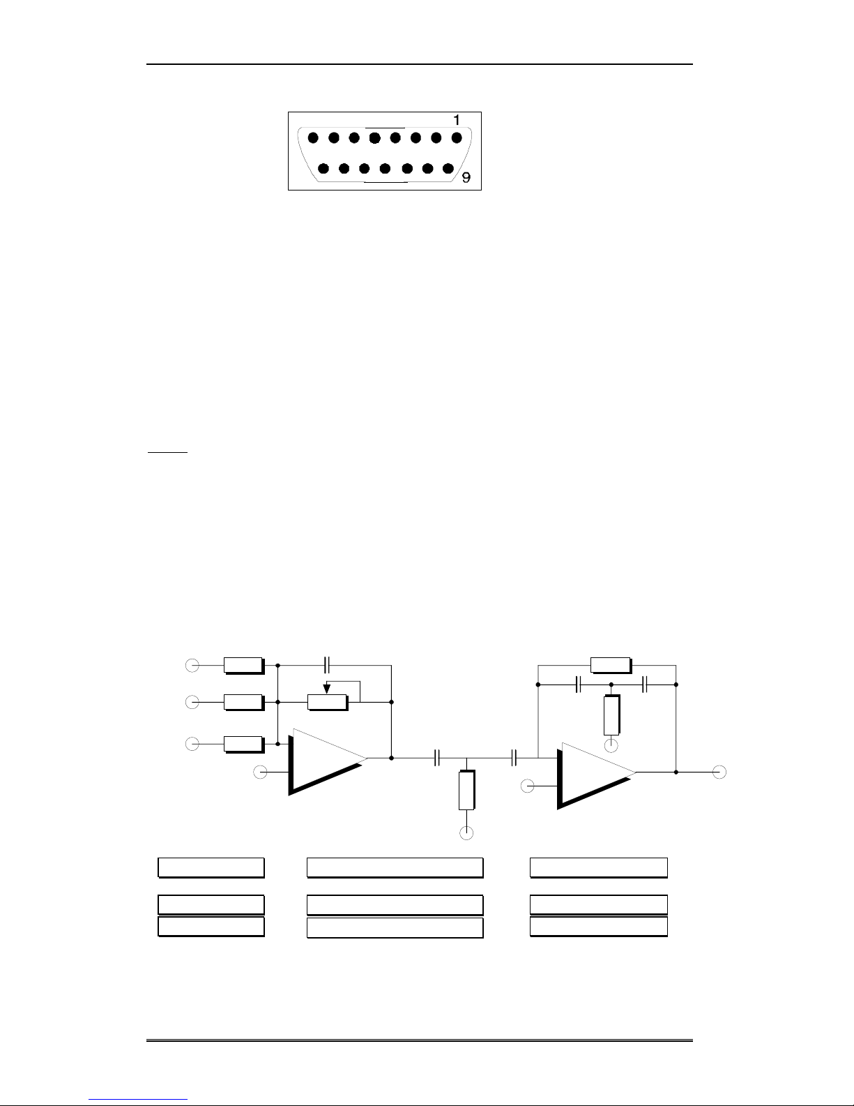
For the radio link the MR1200 uses a 15-way sub-D connector whose pinout is shown below:
Installation
Page 10 ETIC - MR1200 - USER MANUAL - 908709-02
8
15
9 LFout : LF transmit output
11 LFin-: main LF receive input
10 LFin+ : secondary LF receive input (for differential input mode)
1 (, 2, 3) ALT : half duplex control
12 DP : radio carrier detect, or squelch inf. (optional)
6 VREG : Output for T/R power supply relay control
5 GND : T/R signal ground
8 GND : T/R signal ground
14 + 12 V (reserved for modem card power supply from the transceiver)
15 O V (reserved for modem card power supply from the transceiver)
7 : reserved
13 : reserved
4 : reserved
2.6.1.1. The LFout connection
The output stage levels are calculated to match the VCO input of a classic analogue phase modulated
transmitter.
The circuit diagram below shows :
- an amplification stage (IC3-A + R25 + P3) with gain adjustment using the multiturn
potentiometer (P3).
- a signal pre-emphasis stage (IC3-B + C17, C15, C3, C4 + R19, R11, R12), providing the
correct levels at the VCO input to obtain the frequency excursions recommended by the
ST/PAA/DIR/1382 standard.
+
-
+
-
VR
VR
VR
VR
modulating signal radio frequency excursion Tolerances
f0= 1800 Hz
f1= 1200 Hz
∆f0= 1.57 kHz
∆f1= 1.04 kHz
+0.2 kHz / -0.32 kHz
+0.13 kHz / -0.21 kHz
The pre-emphasis stage is in fact a 2nd-order high-pass filter defining the following relationship :

Installation
ETIC - MR1200 - USER MANUAL - 908709-02 Page 11
∆
f1=
∆
f0
1.5 ± 0.12 kH
z
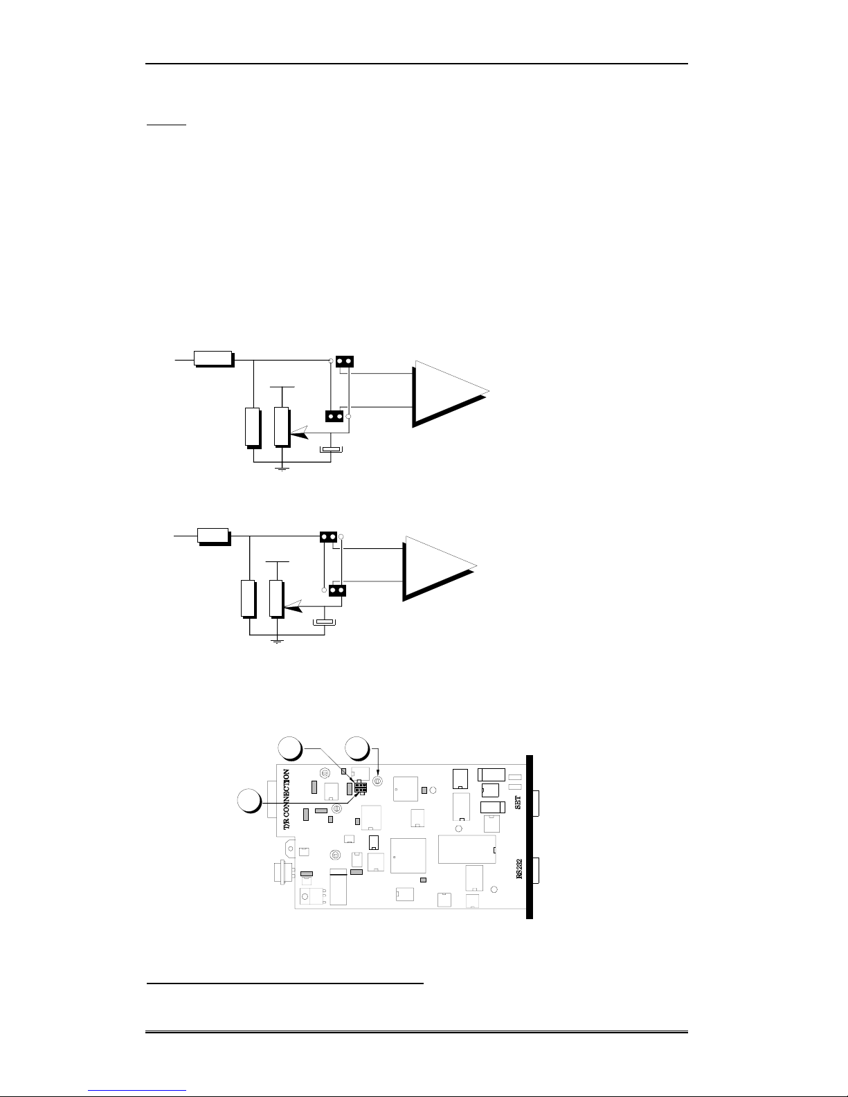
If the transmitter used has an input marked « external mic », it is quite likely that pre-emphasis is
already provided at the input stage. In this case, it is possible to bypass the modem pre-emphasis stage
by moving jumper S5 as shown below.
S5
P3
IC3
Potentiometer P3 then enables the level of the T/R input signal to be set so that the recommended
frequency excursions ∆f0and ∆f1 can be obtained.
P3 is factory set for a signal of 175 mV r.m.s. at 1200 Hz, and 265 mV r.m.s. at 1800 Hz.
Depending on the type of microphone specified for the equipment, the T/R manufacturer may have
used filters having responses that could upset data transmission.
In this case, a complete transmitter frequency response spectrum will be required in order to determine
the characteristics of any compensating filter needed to obtain the recommended radio channel
frequency excursions. The discreet components around IC3-B may be changed to achieve the correct
filter response.
This is a delicate operation requiring radio frequency measuring equipment and an SMD soldering kit
(see ETIC).
2.6.1.2. The LFin connection
The demodulated signal input stage consists of :
- a passive band-pass filter (C12 + R8 + C14)
- an amplification stage(IC3-C + R4 + P1) with gain adjustment using the multiturn
potentiometer (P1).
The high input impedance means the LFin input stage will accept signals from the « audio » or
« external loudspeaker » outputs of most T/Rs.
Where the T/R has a differential output, the network (R9 + R10 + R15 + C9 + C15) allows such an
output to be connected. In this case strap S1 must be moved. Where possible, it is preferable to use the
differential mode configuration since it reduces noise.

Installation
Page 12 ETIC - MR1200 - USER MANUAL - 908709-02
VR
S1
+
-
BFin
+
BFin -
10
11
S1
P1
IC3
The operation requires the copper track (component side) linking the S1 pins to be cut, and a strap
soldered in position as shown above.
P1 is factory set to give an RX level of 460 mV r.m.s. when a signal of 1500 Hz / 85 mV r.m.s. is
applied to the LFin input.
2.6.1.3. The ALT connection
The T/R 's change over to transmit mode (ALTERNAT command) either happens the instant circuit
105-RTS is set ON, or when the ALT command generated by the data card is asserted .
A monostable triggered by 105-RTS prevents T/R changeover occurring before data transmission has
terminated.
RTS
DATA
ALTERNAT Soft
DATA out
10 ms min
T1= 65 ms max
ALTERNAT E/R
MONOSTABLE monostable 100 ms
Installation
ETIC - MR1200 - USER MANUAL - 908709-02 Page 13
2.6.1.4. The DP connection (optional)
In order to avoid collisions, the data card uses the DP signal (carrier detect, or squelch-inf.) to check
the radio channel status before transmitting data.
Not all T/Rs provide a carrier detect /squelch output signal, and in such cases the MR 1200
configuration need not take account of this input.
To generate its «Channel occupied» logic signal the modem compares the DP signal from the
transceiver with a threshold voltage (IC1 + R7 + R20 + R22 + P2 + C6).
The threshold level is adjusted with P2.
Using straps S3 and S4, a positive logic level can be generated whatever the nature of the DP signal
input.
+
-
L5V
S4
DP
Logic +
S3
+
-
L5V
S4
DP
Logic -
S3
Straps S3 and S4 are factory set for a positive DP signal. In the opposite case, straps S3 and S4 need to
be altered. Once the copper tracks (component side) connecting the S3 pins and those between the S4
pins have been cut, straps are soldered into position as shown below.
2.6.2. The type of connecting cable to use
S4
P2S3
Installation
Page 14 ETIC - MR1200 - USER MANUAL - 908709-02
The connection between the MR1200 and the transceiver must be made using a short length of
multicore screened cable.
The screen should be connected to the metal shell of the 15-way sub-D connector.
2.6.3. Factory pre-setting
ETIC can deliver modems pre-configured for the chosen transceiver. Interconnection wiring sheets
have been produced for most models of transceiver on the market.
When ordering :
- specify the make and type of transmitter
- include the FR02 option in the order (modem set-up)
- if the transmitter details are not known to us, option FR03 should also be ordered (transmitter
connection investigation) and 2 units with manuals forwarded which will enable a connection and line
up adjustment sheet to be drawn up.
2.6.4. Particularity of the 2400 b/s version
FFSK modulation at 2400 b/s
For FFSK modulation at 2400 b/s, the sub carriers coding bits 1 and 0 are respectively F1 = 1200 Hz
and F0 = 2400 Hz.
Now, 2400 b/s is at the limit of the transmission chain bandwidth, and any mismatching tolerable at
1200 b/s will now produce signal alterations too severe for the modem to handle. Furthermore, in order
to maintain the bit rate, modulation frequency shifts at crossover take place every quarter cycle, making
the modem more sensitive to signal phase errors.
For transmission : it is advisable to ensure that only one pre-emphasis filter is used : either by taking
the modem output directly to the T/R VCO, or by strapping out the modem filter and using the filter on
the transceiver microphone input (different modulation index),.
For reception : it is imperative to have access to the demodulator output signal directly before the de-
emphasis stage, thus avoiding the different LF stage filters in the receiver which alter the signal too
much to enable data reception to be error free.
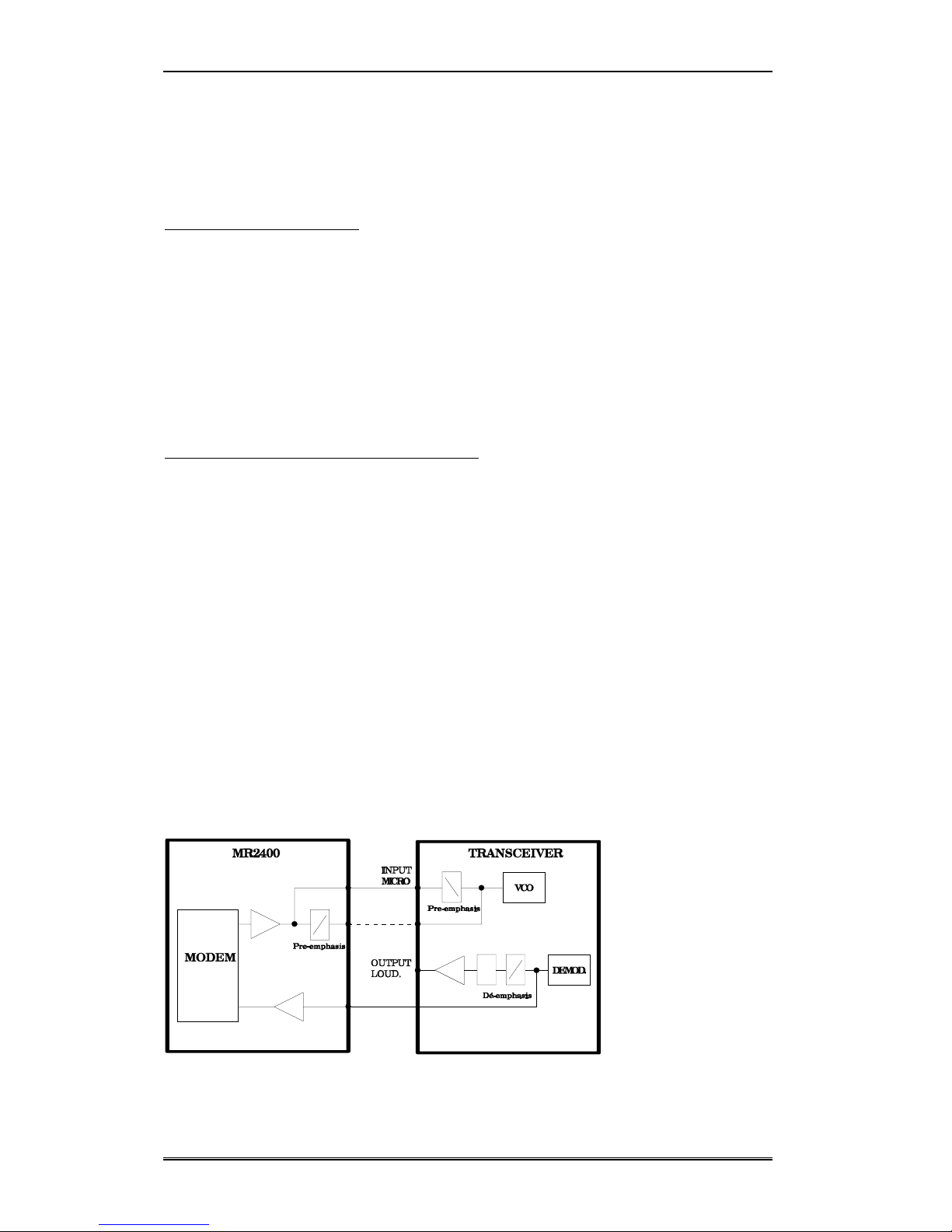
Connection block diagram
Installation
ETIC - MR1200 - USER MANUAL - 908709-02 Page 15
2.7. Power saving feature set up
The power saving feature, not operative when the modem is in its normal "awake" state, comes into
operation when the unit is "asleep". Three jumpers on the data card need to be positioned to configure
the different wake-up modes.
There are two possible sleep modes :
- SLEEP MODE 1 : MR1200 asleep, T/R awake.
Wake up initiated by 108/2-DTR, by radio CD or by the
configuration mode push-button being activated.
- SLEEP MODE 2 : MR1200 asleep, T/R not powered.
In this case, power for the T/R is supplied through a relay
controlled by the MR1200. Relay operation is described in chapter
4.5.3.
Wake up initiated by 108-DTR or by the configuration mode
push-button being activated.
Configuring the straps for SLEEP MODE 1 :
Cut the copper track linking the pins of S12 (component side) and solder a strap in position as
indicated on the drawing below.
If it is desired to confirm modem wake up through the radio CD, solder a strap on S2 as
indicated on the drawing below.
Configuring the straps for SLEEP MODE 2 :
Cut the copper tracks linking the pins of S12 and of S11 (component side) and solder a strap
in position as indicated on the drawing below.
S11
S2
S12

Installation
Page 16 ETIC - MR1200 - USER MANUAL - 908709-02
2.8. Connecting the optional microphone + loudspeaker set
A set compatible with the MR1200 is available, having reference MIC-02.
2.8.1. Description of the microphone/loudspeaker interface
The demodulated signal is amplified (circuit around IC3-D and IC5) in order to directly drive a 4 Ω
loudspeaker.
Warning : the LS output signal is referenced to +5V. The loudspeaker must therefore be connected
between the HP and V+ (+5V) outputs available on the female 9-way sub-D connector.
For a signal of 1500 Hz / 85 mV r.m.s. applied to the LFin input - (transceiver interface), the power
delivered to a 4 ΩLS is approximately 25 mW.
If the set used incorporates amplification (i.e. has a high impedance input), better audio quality can be
obtained by taking the LS signal directly from the output of IC3-D (behind C8), and if necessary
increasing the level by modifying the values of R3 and R17 (consult ETIC).
The pinout of the female 9-way sub-D connector is as shown :
1, 5 : +5 V (cut when the MR1200 is in sleep mode)
2 : LS output
3 : microphone input
4 : transmit control o/p (PTT: connected to pin 5 for transmit)
6 : ground
7 : D- RS485
8 : RS485 Adaptation (to adapt impedance of the RS485 serial link by
connecting pin 7 to pin 8)
9 : D+ RS485
The interface was designed for a particular microphone/LS set, for sale under reference «MIC-02».
Using another kind of set may necessitate modifications to some of the discreet components on the
card.
2.8.2. PTT connection (push to talk)
The MR 1200 needs a TTL logic signal to control the T/R changeover to transmission :
- 0V : wait (reception)
- +5V : transmission

Installation
ETIC - MR1200 - USER MANUAL - 908709-02 Page 17
The PTT signal is derived simply by closing a pair of contacts operated by the changeover button :
+5V
PTT
Boar
d
Push to talk button
2.8.3. MICROPHONE connection
The external microphone signal is amplified and filtered (low-pass filter, IC3-A + C18 + R21 + P3 +
C16).
If necessary, the signal level can altered by modifying resistor R21 (consult ETIC).
2.9. T/R power supply
The transceiver connected to the MR1200 should have an external power source.
For sleep mode operation the VREG output can then be used to control a T/R power supply relay.
MR1200
TRANSCEIVER
RX TX
GND
+ V
Vreg


Configuration
ETIC - MR1200 - USER MANUAL - 908709-02 Page19
3. CONFIGURATION
3.1. Entering configuration mode
Programming or listing the complete set of MR1200 operating parameters may be carried out using a
data terminal connected via the serial interface.
The terminal must be set up with the following communication parameters :
•transmission speed 1200 bits/s
•transmission data format 7E1 (7 bits, even parity, 1 stop)
Once the terminal has been installed and the equipment powered, the operator pushes the
"CONFIGURATION" miniature push-button found on the modem front panel
At this point, any radio communication in progress will be terminated, indicators TR and DP will come
on and the following message will appear on the terminal screen : C >.
2
1
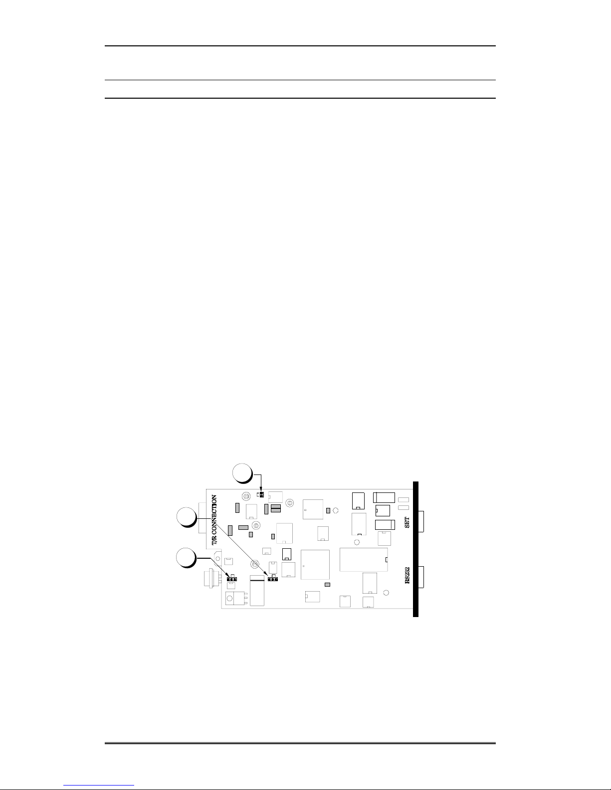
1 : Serial connector for terminal link (male 9-way sub-D)
2 : Miniature push-button switch selects configuration mode
3.2. Configuration commands
Operating parameters and options are programmed into, and read from, the MR1200's E2PROM
memory using commands and responses as defined in the CCITT V25bis standard.

Configuration
Page 20 ETIC - MR1200 - USER MANUAL - 908709-02
Terminal commands Modem responses
### < erroneous command > INV Command invalid
PRPppp;vv...v Programme parameter ppp
with value vv...v
VAL Command accepted
RLPppp Read parameter ppp
RLP PnRead page nof the
configuration (n = 1 or 2).
LSPppp;vv...v Indicates value vv...v of
parameter ppp
LSPppp1;vv...v to
LSPpppn;vv...v Indicates value vvv...v for
parameter ppp1 to pppn.
RES0 Reinitialise terminal-modem
dialogue
VAL Reinitialisation carried out
RES1 Reinitialise modem using the
default parameters
VAL Reinitialisation carried out
Remarks :
•symbols shown by prepresent ASCII numbers,
•the value vv...v of a parameter is given in the form of an ASCII chain ; coding depends on the
parameter,
•all terminal commands must be composed of ASCII characters and terminated by the control
code [Cr] (Carriage Return) or by the [Cr-Lf] (Carriage Return + Line Feed) combination,
•The MR1200 echoes all the commands it receives on the terminal screen. It is always possible to
cancel this echo if the terminal echoes its keyboard input locally.
3.3. Quick configuration
This paragraph describes the minimum configuration necessary to get the modem up and running
quickly.
When completed, the MR1200 will function in automatic mode (communication using 4 serial interface
circuits : 103-TD, 104-RD, 106-CTS and 102-SG). The power saving feature will not be operative.
•Connect an ASCII terminal (type VT100, or a PC emulating VT100) to the MR1200 using a 4-
wire cable carrying circuits 103-TD, 104-RD, 106-CTS and 102-SG of the RS232 serial
interface.
•Apply power to both terminal and modem.
•Configure the terminal's communication port for 1200 bits/s, 7E1, no handshaking.
•Operate the miniature push-button "CONFIGURATION" switch on the MR1200 front panel.
All modem indicators will then come on, and "C>" should appear on the terminal screen.
•Enter the command "RES1" followed by [Cr]. The indicators should go out.
•Operate the "CONFIGURATION" push-button switch once more to turn the indicator lamps on
again and bring back the "C>" cursor.
Table of contents


