Seneca Z-LINK2-LO User manual

MI00602-1-EN INSTALLATION MANUAL 1/4
INSTALLATION MANUAL
SENECA s.r.l.; Via Austria, 26 – 35127 – PADOVA – ITALY; Tel. +39.049.8705359 - Fax +39.049.8706287
WARNING: The full content of this manual must be read before any operation. The module must only be used by
qualied electricians. Specic documentation is available via QR-CODE shown on page 1.
Electrical and electronic waste disposal (applicable in the European Union and other countries with recycling).
The symbol on the product or its packaging shows the product must be surrendered to a collection centre
authorized to recycle electrical and electronic waste.
The module must be repaired and damaged parts replaced by the Manufacturer. The product is sensitive to
electrostatic discharges. Take appropriate measures during any operation.
PRELIMINARY WARNINGS
The word WARNING preceded by the symbol indicates conditions or actions that put the user's safety at risk.
The word ATTENTION preceded by the symbol indicates conditions or actions that might damage the
instrument or the connected equipment. The warranty shall become null and void in the event of improper use or
tampering with the module or devices supplied by the manufacturer as necessary for its correct operation, and if
the instructions contained in this manual are not followed.
CONTACT INFORMATION
This document is the property of SENECA srl. Copies and reproduction are prohibited unless authorised.
The content of this document corresponds to the described products and technologies.
Stated data may be modied or supplemented for technical and/or sales purposes.
DOCUMENTATION
Z-LINK2-LO
Z-LINK2-LO

MI00602-1-EN INSTALLATION MANUAL 2/4
MODULE LAYOUT
Dimensions LxHxD: 17.5 x 102.5 x 111 mm; Weight: 110 g; Enclosure: PA6, black
17.5 mm
111 mm
102.5 mm
LED STATUS LED meaning
L1 Flashing Packet transmission on the bus
L2 Flashing Packet transmission on radio module
L3 ---- Not used
L4 Flashing Module powered correctly
SIGNALS VIA LED ON FRONT PANEL
TECHNICAL SPECIFICATIONS
CERTIFICATIONS
INSULATION
POWER SUPPLY Voltage: 10 ÷ 40Vdc; 19 ÷ 28Vac; 50 ÷ 60Hz; Max: 1W
ENVIRONMENTAL
CONDITIONS
Temperature: -10 ÷ +65°C; Humidity: 30% ÷ 90% non-condensing;
Storage temperature: -20÷ +85°C; Degree of protection: IP20.
ASSEMBLY IEC EN60715, 35mm DIN rail in vertical position.
CONNECTIONS
3-way removable screw terminals, pitch 5mm
Rear connector IDC10 for DIN bar 46277
front microUSB
BAND OF
FREQUENCY BAND ERC 70-03, February 2023, Annex 1, h1.7 (band centre 869.525MHz)
MODULATION LoRa® (CSS Modulation - Chirp Spread Spectrum)
RECEIVER CATE-
GORY 2
RANGE OF
ANTENNAS 450/500 m with supplied Antenna, 700/800 m with Magnetic Antenna.
Communication
Power
Supply
Input Output
RS485 RS232
1500 Vac

MI00602-1-EN INSTALLATION MANUAL 3/4
ModBUS CONNECTION RULES
1) Install the modules in the DIN rail (120 max)
2) Connect the remote modules using cables of an appropriate length. The following table shows cable length data:
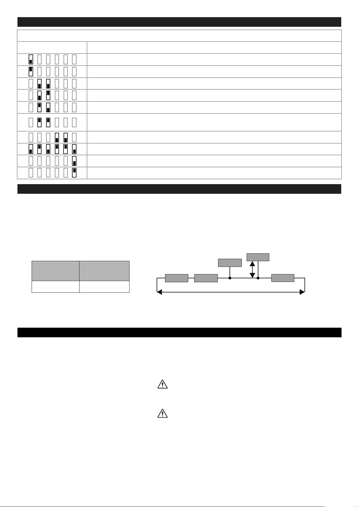
-Bus length: maximum length of the Modbus network according to the Baud Rate. This is the length of the cables that connect
the two farthest modules (see Diagram 1).
-Derivation length: maximum length of a derivation 2 m (see Diagram 1).
Ld
For maximum performance, it is recommended to use special shielded cables, such as BELDEN 9841.
SETTING THE DIP-SWITCHES
SW1
1 2 3 4 5 6
The device is connected to ModBUS slave modules
The device is connected to the ModBUS Master or is operating as ModBUS Master
38400 baud - 8N1
19200 baud - 8N1
9600 baud - 8N1
Communication parameters from EEPRON (default: 38400 baud - 8N1)
N.B.: any change must be performed only using the Easy Setup 2 software
The radio module is internally connected to IDC10 (Seneca RS485 bus) and to terminals 7-8-9
Programming mode with Easy Setup
ModBUS RS485 enabled
ModBUS RS485 disabled
INSTALLATION REGULATIONS
The module has been designed for vertical installation on a DIN 46277 rail. For optimal operation and long life, adequate
ventilation must be provided. Avoid positioning ducting or other objects that obstruct the ventilation slots. Avoid mounting
modules over heat-generating equipment.
Installation in the bottom part of the electrical panel is recommended.
These are open type devices intended for installation in a nal casing/panel that offers mechanical protection and protection
against the spread of re.
CAUTION
CAUTION
Bus length
1200 m 2 m
Diagram 1
Bus length
Module 1 Module 2
Module 3
Module 4
Module 5
Ld = Derivation length
Derivation
length
To congure the device via the Easy Setup software, the master device must be switched off.

MI00602-1-EN INSTALLATION MANUAL 4/4
Power supply
Terminals 2 and 3 can be used to provide the module with power supply as an alternative to
the connection using the Z-PC-DINx bus.
Power voltage must be between 10 and 40Vdc (any polarity) or between 19 and 28Vac.
The upper limits must not be exceeded in order to avoid serious damage to the module.
If the power supply source is not protected against overload, a safety fuse with a 1A max
permissible value must be installed in the power supply line.
RS232 serial port
The module has a serial port that can be congured with the SW2 switch.
The illustration shows how to complete connections.
The RS232 interface is fully settable.
RS485 serial port
The module has a serial port that can be congured with the SW2 switch.
The illustration shows how to complete connections.
N.B.: the indication of the RS485 connection polarity is not standardised and in some
devices may be inverted.
7
8
9GND
A (+)
B (-)
4
5
6GND
RX
TX
1
2
3
Vac/Vdc
Vac/Vdc
ELECTRICAL CONNECTIONS
Power supply and Modbus interface are available using the Seneca DIN rail bus, via the IDC10 rear connector, or the
Z-PC-DINAL2 accessory.
RS485GND
RS485A
RS485B
Power Supply AC / +
Power Supply AC / -
IDC 10
1
Back connector (IDC 10)
The illustration shows the meanings of the various IDC10
connector pins if signals are to be sent via them directly.
Other manuals for Z-LINK2-LO
1
This manual suits for next models
1
Table of contents
Other Seneca Radio Modem manuals