EURA DRIVES EM30 Series User manual

www.euradrives.eu Software Version 1.03
© 2015 EURA Drives GmbH
Safety instructions Installation
& operating manual
FREQUENCY INVERTER
EM30
0,4kW – 7,5kW

EM30
·0·
CONTENTS
I. Product ……………………………………………………………….. …
1.1 Product model naming rule……………………………………
1.2 Optional function naming rule…………………………………
1.3 Nameplate……..………………………………………………
1.4 Technical parameters….………………………………………
1.5 Technical Specifications ………………………………………
1.6 Appearance………………………………………………….…
1.7 Designed Standards for Implementation…………….….……
1.8 Safe Instructions and Precautions……………………….……
1.9 Examination and Maintenance…………………………..……
II. Keypad panel………………………………………………………..
2.1 Panel Illustrations………………………………………………
2.2 Panel Structure………………………………………………. …
2.3 Panel Operating ………………………………………………
2.4 Parameters Setting ……………………………………………
2.5 Function Codes Switchover In/Between Code-Groups…..……
2.6 Operating instructions of 4-line LCD interface switch……….
2.7 Panel Display …………………………………………………
III. Installation & Connection ………………………………………………
3.1 Periphery Wiring……………………………………………….
3.2 Installation………………………………………………….…
3.3 Connection…………………………………………………….
3.4 Function of Control Terminals……………………………………
3.5 Measurement of Main Circuit……………………………………
3.6 Overall Connection………………………………..…….……
3.7 Solutions of Conduction and Radiation Interference…………..
IV. Operation and Simple Running ………………………………………
4.1 Basic conception………………………………………………
1
1
2
3
3
4
5
6
6
8
9
9
10
12
12
13
14
15
16
16
18
19
21
24
26
27
32
32
38

EM30
·1·
4.2 Keypad panel and operation method……………………………
4.3 Illustration of basic operation…………………………………
V. Function Parameters ……………………………………………………
5.1 Basic Parameters…………………………………………………
5.2 Operation Control …………………………………………….. …
5.3 Multifunctional Input and Output Terminals………………………
5.4 Analog Input and Output………………………………….………
5.5 Pulse Input and Output control………………………….…………
5.6 Multi-stage Speed Control….………………….…………………
5.7 Auxiliary Functions…..……………………..…….…………
5.8 Malfunction and Protection………………….……………………
5.9 Parameters of the motor….……………………..……………
5.10 Communication parameters………..……………………….……
5.11 PID parameters………………………………………………
5.12 Torque control parameters………………………………….
5.13 Parameters Display…………………………………………
VI. Maintenance....................................................................................
6.1 Daily Inspection....................................................................
6.2 Periodic Maintenance............................................................
6.3 Exchange of Vulnerable Parts...............................................
6.4 Storage..................................................................................
VII. Motor……………………………………………………………..
7.1 Nameplate…………………………………………………..
7.2 Naming Rule…………………………………………………
7.3 Motor Technical Specification……………………………….
7.4 Motor Type…………………………………………………...
7.5 Reference Table of inverter and motor……………………..
7.6 Motor Installation Size………………………………………
7.7 Installation…………………………………………………..
7.8 Trouble Shooting…………………………………………..
7.9 Maintenance & Servicing………………………………….
33
36
41
41
50
58
68
71
74
77
84
88
92
93
97
99
101
101
101
102
102
103
103
104
106
107
110
111
113
113
115

EM30
·2·
Appendix 1 Trouble Shooting…………………………………..…….…
Appendix 2 Reference Wiring of Water System……………..…….……
Appendix 3 Products and Structure…..……………..…………..……
Appendix 4 Selection of Braking Resistance……………..………….….
Appendix 5 Communication Manual……..………….…………. ……
Appendix 6 Zoom Table of Function Code……………………………
.
116
119
121
123
124
134
EM30
·1·
I. Product
This manual offers a brief introduction of the installation connection, parameters setting
and operations for EM30 series inverters, and should therefore be properly kept. Please
contact manufacturer or dealer in case of any malfunction during application.
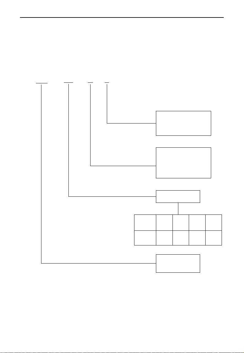
1.1 Product model naming rule
EM30 0007 T3 J1
Structure Code:
J1: 270*190*165
J2: 338*228*193.5
Input Voltage:
T3: 3-phase 380VAC Input
S2: 1-phase 220VAC Input
T2: 3-phase 220VAC Input
Motor Power
Mark
Power
(kW)
0004 0007 0015 „„
0.4 0.75 1.5 „„
Realation
Product Series:
EM30 series

EM30
·2·
1.2 Optional function naming rule
U5 F2 AC02 B1 R3 M1 IC1
Mark Installation Type
None
IC1
No wall-mounted bracket
Wall-mounted bracket
Mark Motor Type
None
M1
M2
No motor-mounted
Induction Motor
PM synchronous Motor
Mark Filter Type
None No filter
R3 C3 level filter
Mark
None
B1
Brake Mode
No braking unit
Built-in braking unit
Mark Keypad Panel Type
AC02
AC04
AC English keypad panel, 4-line LCD display,
without potentiometer
AC Chinese keypad panel, 4-line LCD display,
without potentiometer
Mark Field Bus Type
None
F2 MODBUS with terminal interface
None
Mark
None Certification Type
U
U1
U5
None
UL
CE
UL+CE
EM30
·3·
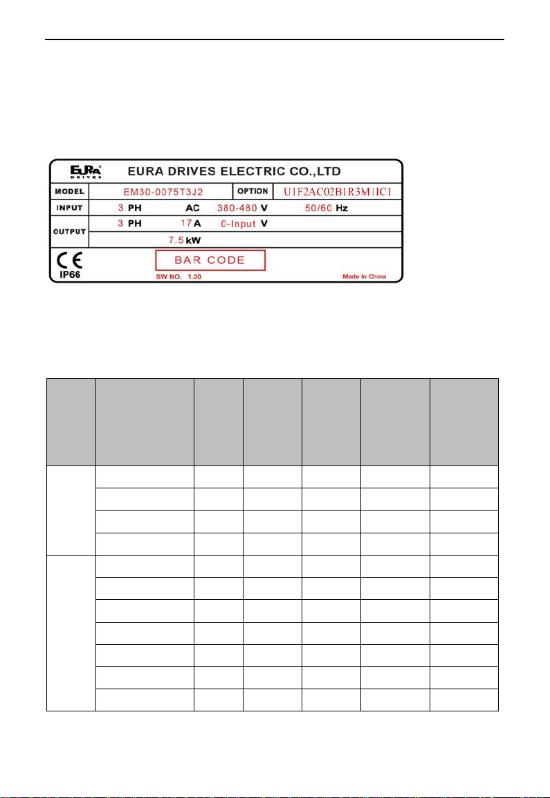
1.3 Nameplate
Taking for instance the EM30 series 7.5kW inverter with 3-phase 400V input, its
nameplate is illustrated as Fig 1-1.
3PhAC: 3-phase input;
380~480V, 50/60Hz: Input voltage range and rated frequency.
3Ph: 3-phase output; 17A, 7.5kW: Rated output current and power;
Fig 1-1 Nameplate
Note: Integrated inverter model include product model and optional function model. Make
sure to fill with complete integrated inverter model to avoid mistakes when making an
order.
1.4 Technical parameters
Power
supply
Model
Motor
Power
(kW)
Rated
Input
Current
(A)
Rated
Output
Current
(A)
Input
Protection
Current
(A)
Efficiency
(%)
1Ph
230V
EM30-0004S2
0.4
6
2.5
10
≥95
EM30-0007S2
0.75
10
4.5
18.1
≥96
EM30-0015S2
1.5
14
7
25.2
≥96
EM30-0022S2
2.2
20.0
10
32.0
≥96
3Ph
400v
EM30-0007T3
0.75
3.0
2
6.5
≥95
EM30-0015T3
1.5
5
4
11
≥95
EM30-0022T3
2.2
7.5
6.5
15.0
≥96
EM30-0030T3
3.0
8
7
16
≥96
EM30-0040T3
4.0
11.0
9
21.0
≥96
EM30-0055T3
5.5
14.0
12
29.0
≥96
EM30-0075T3
7.5
18.5
17
34.0
≥96

EM30
·4·
1.5 Technical Specifications
Table1-1 Technical Specifications for EM 30 Series Inverters
Items
Contents
Input
Rated Voltage Range
T3 380V-480V(+10%/-15%);S2/T2 220V-240V (±15%)
Rated Frequency
50/60Hz
Output
Rated Voltage Range
3-Phase: 0-INPUT(V)
Frequency Range
Vector Control Model: 0~500.00Hz;
VF Model: 0~650.00Hz
Control
Mode
Control Mode
Induction Motor: Sensorless Vector Control (SVC), V/F control;
PMSM: open-loop vector control (SVC)
Carrier Frequency
0.8~16KHz;Fixed carrier-wave and randomcarrier-wave (F159)
Modulation Mode
Space Vector PWM
Speed-control Scope
Induction Motor-SVC 1:100; PMSM-SVC 1:20;
SteadySpeedPrecision
±0.5%(SVC)
TorqueResponse
<20ms(SVC)
TorqueControlPrecision
±5%(SVC)
Start Torque
0.5 Hz/100% (VVVF); 0.5Hz/150%(SVC)
DC Braking
DCbraking frequency: 0.20-50.00Hz,;
Braking time:0.00~30.00s;Braking current: 0.0~100%
Operation
Function
Jogging Control
Jogging frequency range: min frequency~ max frequency,
Jogging acceleration/deceleration time: 0.1~3000.0s
Frequency Setting mode
Potentiometer or external analog signal (0~5V, 0~10V,
0~20mA); Keypad (terminals) up/down key; External control
logic and self-circulation setting.
Main Frequency Source
Digital given memory, external analogueAI1, AI2, input
pulse frequency given(100KHZ), digital given without
memory, PID, MODBUS
Auxiliary Frequency Source
Flexible auxiliary frequency trim and the operate mode of main
and auxiliary frequency.
Auto voltage regulation
(AVR)
When source voltage changes, the modulation rate can be
adjusted automatically, so that the output voltage is unchanged.
Analog input
2-channel(AI1/AI2)
Analog output
2-channel (AO1/AO2)
Digit input
5-channel general-form input;
1-channel high-speed pulse input
Max frequency: 100Khz,Internal impedance: 3.3KΩ;
Digit output
1-channel DO1
Relay output
2-channel programmable relay output
Others
Built-in PID adjusting, oscillation inhabitation, common DC
bus, auto carrier modulation, auto fast current-limiting, I/O
terminals self-checking function and OE automatic adjustment.
Keypad
4-line LCD
Support
Parameter copy
Clone module supported.
Protection
Function
Power supply under-voltage, phase loss, DC over-voltage, over-current, inverter overload,
motor overload, output phase loss, overheat, external disturbance, parameter measure failure,
analog line disconnected protection, DC-GND short circuit, water shortage protection,
pressure protection, dormant state.

EM30
·5·
Environmental
Conditions
Environment Temperature
-10℃~+40℃
Environment Humidity
Below 90% (no water-bead coagulation)
Vibration Strength
4G
Height above sea level
1000m or below(Derating use when above 1000m)
Protection
level
IP66
Applicable
Motor
0.4~7.5kW
Efficiency
≥93%
Others
Cooling Mode
Force-air cooling
Braking Unit
Built-in braking unit needs external braking resistor.
Fan
Draught fan is pluggable.
Installation Mode
Support installing with motor
1.6 Appearance
The external structure of EM30 series inverter: die-casting aluminum housing,
anti-fingerprints fabrication processing, unique shape, high strength, good tenacity and
convenience for maintenance. Taking EM30-0022T3J1 for instance, the external
appearance and structure are shown as below in Fig1-2.
Fig 1-2 Appearance and Structure
EM30
·6·
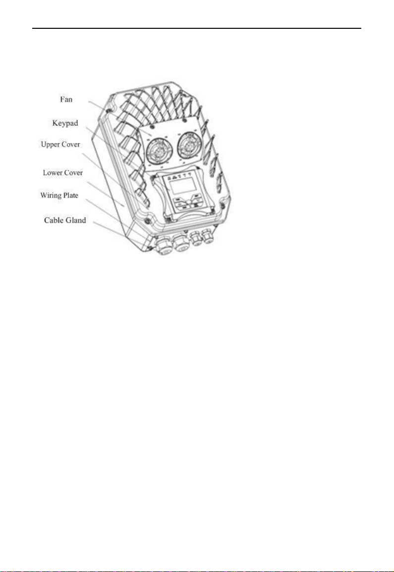
Exquisite structure design of aluminum casting housing, detachable cover structure and
convenient connection can realize perfect combination with motor. Take EM30-0075T3J2
for instance, the external appearance and structure are shown as below in Fig1-3.
Fig 1-3 Appearance and Structure
1.7 Designed Standards for Implementation
IEC/EN 61800-5-1: 2007 Adjustable speed electrical power drive systems safety
requirements.
IEC/EN 61800-3: 2004/+A1: 2012 Adjustable speed electrical power drive systems-Part 3:
EMC product standard including specific test methods.
1.8 Safe Instructions and Precautions
Please check the model in the nameplate of the inverter and the rated value of the
inverter. Please do not use the damaged inverter in transit.
Installation and application environment should be free of rain, drips, steam, dust
and oily dirt; without corrosive or flammable gases or liquids, metal particles or
metal powder. Environment temperature within the scope of -10℃~+40℃.
Please install inverter away from combustibles.
Do not drop anything into the inverter.
The reliability of inverters relies heavily on the temperature. The around temperature
increases by 10℃, inverter life will be halved. Because of the wrong installation or
fixing, the temperature of inverter will increase and inverter will be damaged.
Inverter is installed in a control cabinet, and smooth ventilation should be ensured
and inverter should be installed vertically. If there are several inverters in one
cabinet, in order to ensure ventilation, please install inverters side by side. If it is
necessary to install several inverters up and down, please add heat-insulation plate.

EM30
·7·
Never touch the internal elements within 15 minutes after power off. Wait till it is
completely discharged.
Input terminals L1/R, L2/S and L3/T are connected to power supply of 400V/230V
(L1, L2 are connected to 230V) while output terminals U, V and W are connected to
motor.
Proper grounding should be ensured with grounding resistance not exceeding 4Ω;
separate grounding is required for motor and inverter. Grounding with series
connection is forbidden.
There should be separate wiring between control loop and power loop to avoid any
possible interference.
Signal line should not be too long(less than 3m) to avoid any increase with common
mode interference.
If circuit breaker or contactor needs to be connected between the drive and the motor,
be sure to operate these circuit breakers or contactor when the drive has no output,
to avoid damaging of drive.
Meet the environmental requirements of EM30 series technical specifications in
table 1-1.
Before using the drive, the insulation of the motors must be checked, especially, if it is
used for the first time or if it has been stored for a long time. This is to reduce the risk of
the drive from being damaged by the poor insulation of the motor.
Do not connect any varistor or capacitor to the output terminals of the drive, because the
drive‘s output voltage waveform is pulse wave, otherwise tripping or damaging of
components may occur; in addition, do not install circuit breaker or contactor at the
output side of the drive as shown in Fig 1-4.
Fig 1-4 Capacitors are prohibited to be used.
Derating must be considered when the drive is installed at high altitude, greater than
1000m. This is because the cooling effect of drive is deteriorated due to the thin air,
as shown in Fig. 1-5 that indicates the relationship between the elevation and rated
current of the drive.
Inverter M

EM30
·8·
Fig 1-5 Derating drive‘s output current with altitude
Never touch high-voltage terminals inside the inverter to avoid any electric shock.
Before inverter is powered on, please be sure that input voltage is correct.
Please do not connect input power supplyonto U,V,W or terminals.
Please do not install inverter directly under sunshine, do notblock upthe cooling hole.
All safety covers should be well fixed before inverter is power connected, to avoid
any electric shock.
Only professional personnel are allowed for any maintenance, checking or
replacement of parts.
No live-line work is allowed.
1.9 Examination and Maintenance
1.9.1 Periodic checking
Cooling fan and wind channel should be cleaned regularly to check whether it is
normal; remove the dust accumulated in the inverter on a regular basis.
Check inverter‘s input and output wiring and wiring terminals regularly and check if
wirings are ageing.
Check whether screws on each terminals are fastened.
Check whether inverter is corrosive.
1.9.2 Storage
Please put the inverter in the packing case of manufacture.
If inverter is stored for long time, please charge the inverter every half a year to
prevent the electrolytic capacitors damaged. The charging time should be longer
than 5 hours.
1.9.3 Daily Maintenance
Environment temperature, humidity, dust and vibration would decrease the life of inverter.
Daily maintenance is necessary to inverters.
Daily inspecting:
Inspecting for noise of motor when it is working.
Inspecting for abnormal vibration of motor when it is working.
Inspecting for the installing environment of inverter.
Inspecting for the fan and inverter temperature.
Daily cleaning:
Keep the inverter clean. Clean surface dust of inverter to prevent dust, metal powder,
oily dirt and water from dropping into the inverter.
Iout
(m)
100%
90%
80%
1000 2000 3000
Fig 1-7 Derating Drive’s output current with altitude
EM30
·9·
II. Keypad panel
The keypad function and indicator function for EM30 series will be showed in panel operating illustration.
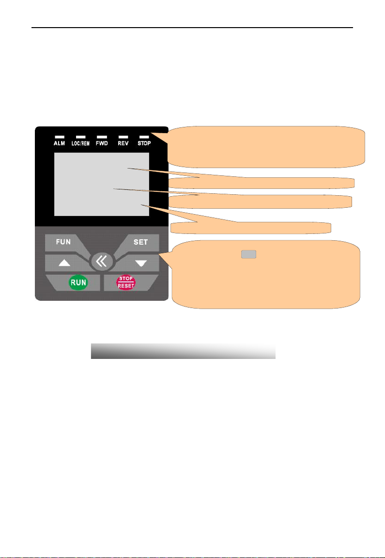
2.1 Panel Illustration
The panel covers three sections: data display section, status indicating section and keypad operating section,
as shown in Fig. 2-1.
F100=0
Basic Parameters
User Password
Press FUN to return
Instructions for operation panel:
1. Please select AC keypad (AC02: English keypad, 4-line LCD; AC04: Chinese keypad,
4-line LCD) for local control.
2. Local keypad panel can be introduced remotely. Select remote fittings if remote panel
is needed.
Fig.2-1 Operation Panels
5 indicators indicate working status. ALM blinks when fault occurs.
LOC/REM blinks in the remote-controlling status. FWD is ON when
rotatingforward,REVisONwhenrotatingreversely,andSTOPisalways
ONwhennotrunning..
Function definition
Press ―FUN‖for calling function code, and ―SET‖for
original parameters.
<<
, ▲and ▼keys can be used to
select function codes and parameters. Press ―SET‖again to
confirm. In the mode of keypad control, ▲and▼keys can
also be used for dynamic speed control. ―Run‖and
―Stop/Reset‖keys control start and stop. Press
―Stop/Reset‖key to reset inverter when in fault status.
Display and value of function code
Operation guidance
EM30
·10·
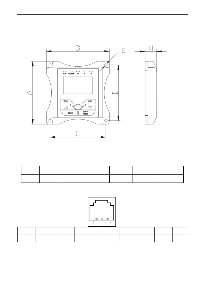
2.2 Keypad panel and installation bracket structure
2.2.1 Structure Diagram
2.2.2 Structure Size (Unit: mm)
Code
A
B
C
D
H
E
XX-X
115
115
102
102
21
Φ4.5
2.2.3 Port of Control Panel
Pins
1
2
3
4
5
6
7
8
8 core
Reserved
5V
5V GND
5V GND
Signal1
Signal2
Signal3
Signal4
Note: The interface of control board should be completely consistent with the interface of
the keypad panel, so the line sequence should also be the same.
EM30
·11·
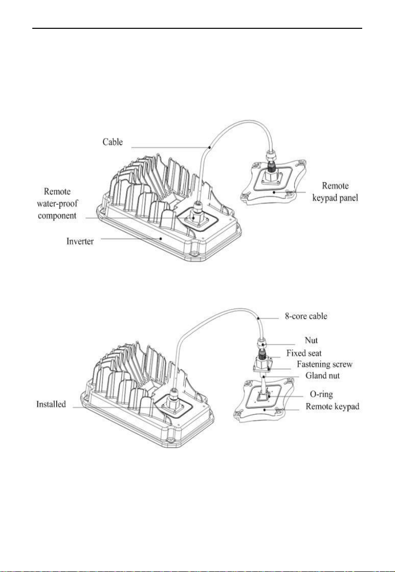
2.2.4 The remote-control components should reach the protection grade. The default
remote-control wire length is 1m. The length of remote-control wire can be custom-made
by users. If on the occasion of strong interference of occasion, or the length is longer than
3m, please put a magnetic ring on the wire to avoid interference. The figures of
remote-control components are showed as below
EM30
·12·
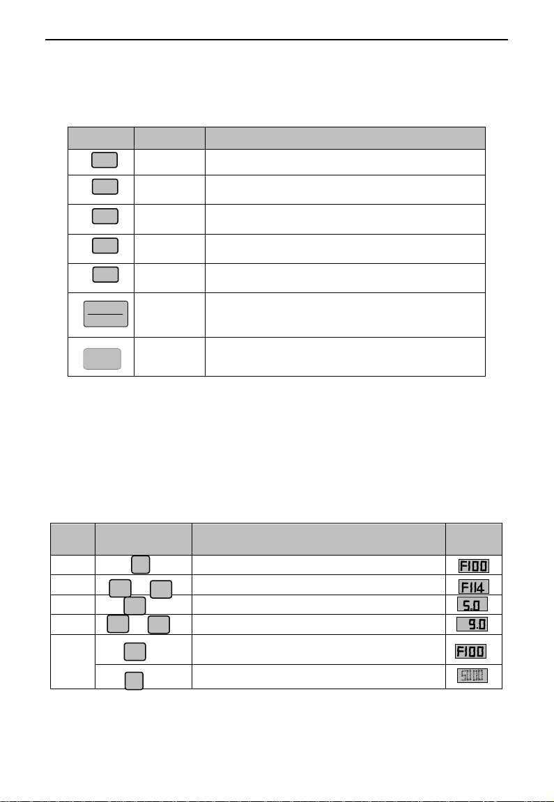
2.3 Panel Operating
All keys on the panel are available for user. Refer to Table 2-1 for their functions.
Table 2-1 Uses of Keys
Keys
Names
Remarks
Fun
To call function code and switch over display mode.
Set
To call and save data.
Up
To increase data (speed control or setting parameters)
Down
To decrease data (speed control or setting parameters)
Run
To start inverter;
STOP
RESET
Stop or reset
To stop inverter; to reset in fault status;
<<
Shift key
Shift and displaying items switchover.
2.4 Parameters Setting
This inverter has numerous function parameters, user can modify to effect different modes of operation
control. User needs to realize that if user sets password valid (F107=1), user‘s password must be entered
firstly if parameters need to set after power off or protection is effected, i.e., to call F100 as per the mode in
Table 2-2 and enter the correct code. User‘s password is invalid when leaving factory and user could set
corresponding parameters without entering password.
Table 2-2 Steps for Parameters Setting
Steps
Keys
Operation
Display
1
Press ―Fun‖ key to display function code
2
Press ―Up‖ or ―Down‖ to select required function code
3
To read data set in the function code
4
To modify data
5
To display corresponding function code after saving the
set data
To display the current function code
The above-mentioned step should be operated when inverter is in stop status.
Fun
▲
▼
or
Set
Set
Fun
▲
▼
or
FUN
SET
RUN
▲
▼
F
1
1
4
EM30
·13·
2.5 Function Codes Switchover in/between Code-Groups
It has more than 300 parameters (function codes) available to user, divided into 11 sections as indicated in Table 2-3.
Table 2-3 Function Code Partition
Group Name
Group
No.
Group Name
Group
No.
Basic Parameters
F1
Timing control and protection
function
F7
Run Control Mode
F2
Parameters of the motor
F8
Multi-functional
input/outputterminal
F3
Communication parameters
F9
Analogsignals and pulse of
input/output
F4
PID parameter setting
FA
Multi-stage speed
parameters
F5
Torque control parameters
FC
Subsidiary function
F6
Parameter display
H0
As parameters setting costs time due to numerous function codes, such function is specially designed as
―Function Code Switchover in a Code Group or between Two Code-Groups‖ so that parameters setting
become convenient and simple.
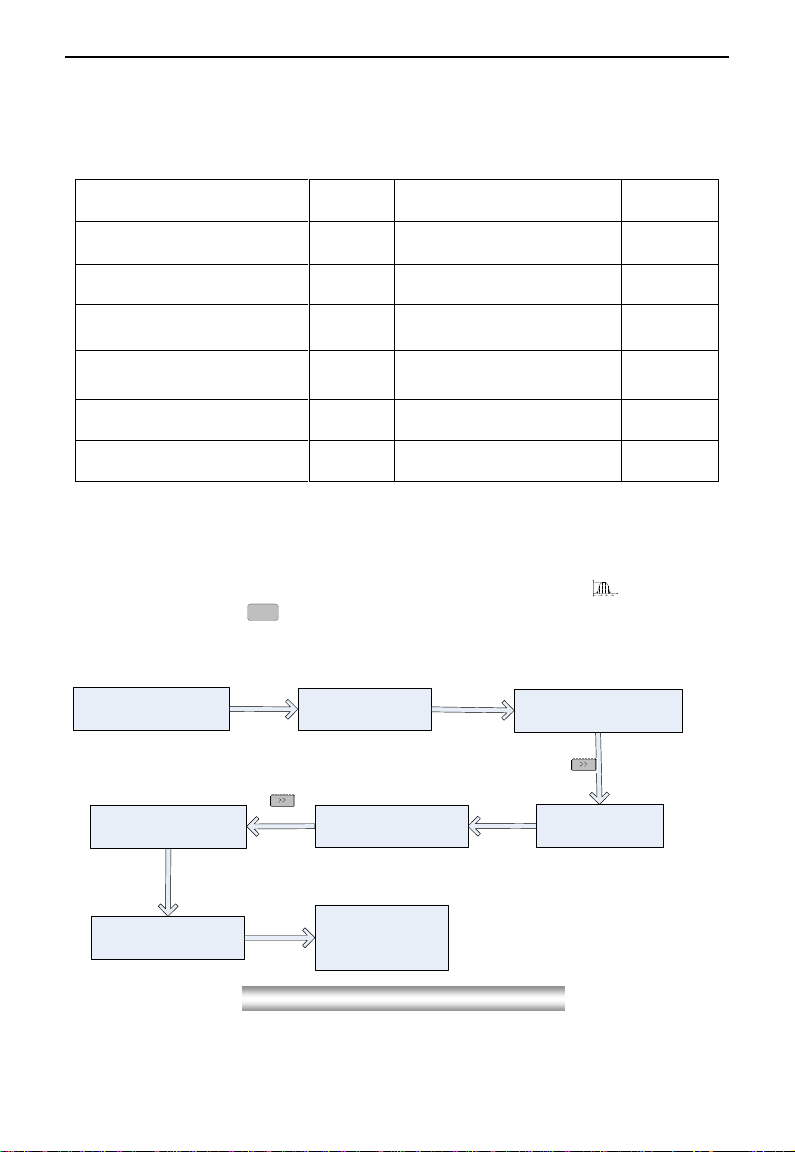
The operation of four-line LCD:
When function code shows F100 and the last ―0‖in F100 is flashing, after pressing
T1 T2
Time
TargetFre
①①
②
③
②
③
key, the middle
―0‖is flashing, then press
<<
again, ―1‖in F100 is flashing, the flashing value can be changed by
pressing ―▲‖/―▼‖ key.
Fig2-2SwitchoverinaCodeGrouporbetweenDifferentCode-Groups
Currently showing
50.00
Press FUN key F100 is displayed.
0 in F101 is
flashing.
F100 changes into
F101/F102/F103„
Press
▲key
Press
▲or
▼key
F101changes into
F111/F121/F131„
Press
The first “1”in
F111 is flashing.
key
▲or
▼
F111
F211/F311/F411„
To set the function
code value, or
change it.
Press SET key
Press key
Press key
changes into
EM30
·14·
2.6 Operating instructions of 4-line LCD interface switch
2.6.1 Operating instructions of SET/FUN keys
Basic parameter
User password
F100= 0
Press FUN to return
Press
FUN
0.00 Hz
Current frequency
50.00 Hz
Target frequency
Stop status
Stop status
Long press SET
Loosen SET
Keypad version: 1.01
Current frequency
50.00 Hz
Target frequency
Basic parameter
User password
F100= 0
0~9999
Press
SET/FUN Press
SET
2.6.2 Operating instructions of inverter status display
0.00 Hz
Current frequency 0.00 rpm
Current rotate speed
F645=1
50.00 Hz
Current frequency F645=1 1500 rpm
Current rotate speed
0.00 rpm
Current rotate speed
50.00 Hz
Target frequency
0.00 Hz
Current frequency
50.00 Hz
Target frequency
F645=1
F645=0
F132=0
F131=0
Fig2-3Operatingflowchart ofinterface switch
Fig2-4Operatingflowchart ofstatus parameterdisplay

EM30
·15·
2.6.3 Regulating target frequency/target rotate speed by UP/DOWN keys in running status
0.00 Hz
Current frequency
50.00 Hz
Target frequency
Press
RUN
50.00 Hz
Current running frequency
1500 rpm
Current rotate speed
1300 rpm
Target rotate speed
1300 rpm
Current rotate speed
Long press
▼key
Loosen
▼key
49.00 Hz
Target frequency
538 V
DC bus voltage
49.50 Hz
Target frequency
538 V
DC bus voltage
Long press
▲key
Loosen
▲key
49.00 Hz
Current frequency
49.00 Hz
Current frequency
48.98 Hz
Target frequency
48.98 Hz
Current frequency
Long press
▼key
Loosen
▼key
Current status is
current rotate speed
Current status is
DC bus voltage
Current status is
current frequency
2.7 Panel Display
Table 2-4 Items and Remarks Displayed on the Panel
Items
Remarks
Power on….
It stands for power on process.
OC, OC1, OE, OL1,
OL2, OH, LU, PF0,
PF1,PCE
Fault code, indicating ―over-current OC‖, ―over-current OC1‖, ―over-voltage‖,
―inverter over-load‖, ―motor over-load‖ ―over-heat‖, ―under-voltage for input‖,
―phase loss for output‖, ―phase loss for input‖, and ―detuning fault‖respectively.
AErr, EP, nP, Err5
Analog line disconnected, inverter under-load, pressure control, PID parameters
are set wrong,
ESP
During two-line/three line running mode, ―stop/reset‖key is pressed or external
emergency stop terminal is closed, ESP will be displayed.
F152
Function code (parameter code).
10.00
Indicating inverter‘s current running frequency (or rotate speed) and parameter
setting values, etc.
50.00
Blinking in stopping status to display target frequency.
0.
Holding time when changing the running direction. When ―Stop‖ or ―Free Stop‖
command is executed, the holding time can be canceled
Fig2-5Operatingflowchart oftargetfrequency/rotatespeedadjustments

EM30
·16·
III.Installation & Connection
3.1 Periphery Wiring
Note: Braking unit is built in the T3 model of EM30 series, braking resistor is need only if the load
inertia is not too large.
Other manuals for EM30 Series
1
This manual suits for next models
11
Table of contents
Other EURA DRIVES Inverter manuals

Popular Inverter manuals by other brands

Lenze
Lenze SMD Series operating instructions

Go Power! Electric
Go Power! Electric GP-DC-KIT2 owner's manual

Mitsubishi Electric
Mitsubishi Electric 800 Series Instruction Manual (Function

Hoymiles
Hoymiles HM-1500N Quick installation guide

Panasonic
Panasonic S-160PE1R5A Technical data and service manual

GenixGreen
GenixGreen JLS-ESS2-2kwh user manual


