Euramco Safety Ramfan EX150Li User manual

San Diego |Luxembourg |Dubai |Ningbo | Singapore
FlowPath™Control
Owner's Manual
ALL PURPOSE-BATTERY VENTILATOR
EX150Li

2
CONTENTS
Introduction .................................................................................................................................... 3
About Euramco ................................................................................................................ 3
Warning Labels and Safety Instructions ........................................................................ 4
Safety Checklist ................................................................................................................ 5
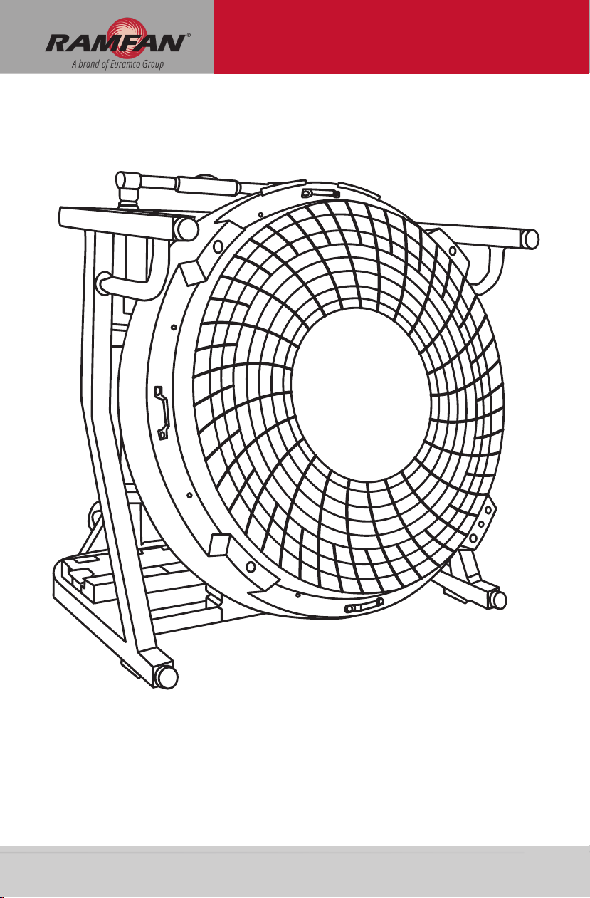
Unit Description .............................................................................................................................. 5
Parts List ............................................................................................................................ 5
Technical Specications .................................................................................................. 6
Dimensions ....................................................................................................................... 6
Main Interface .................................................................................................................. 7
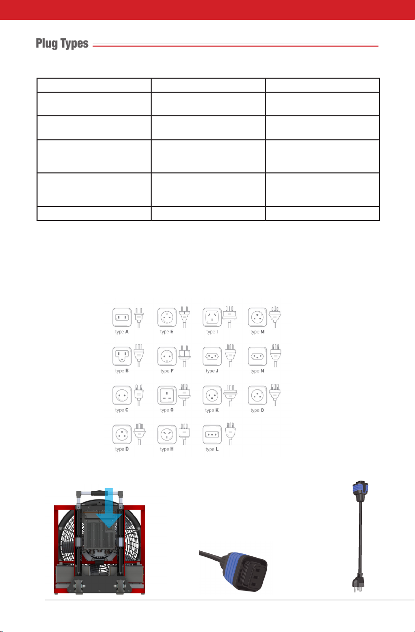
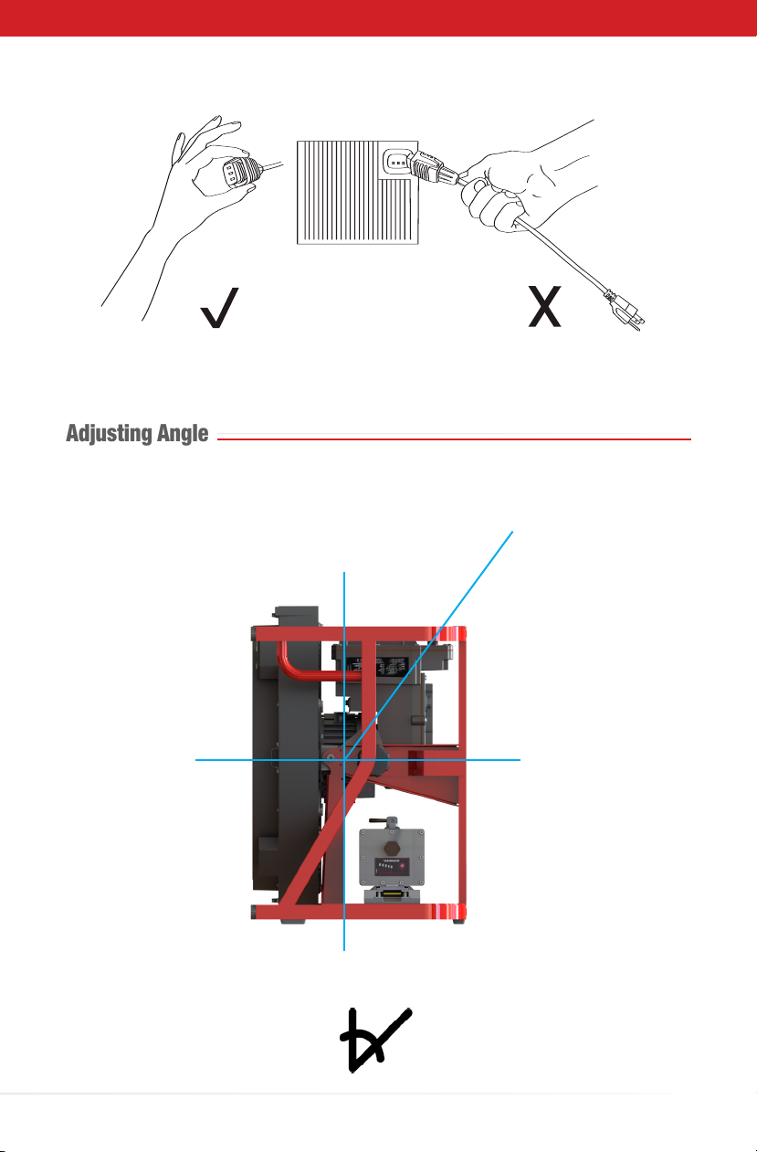
Plug Type .......................................................................................................................... 8
Adjusting Angle ................................................................................................................ 9
Operational Modes ...................................................................................................................... 10
AC Operation .................................................................................................................. 10
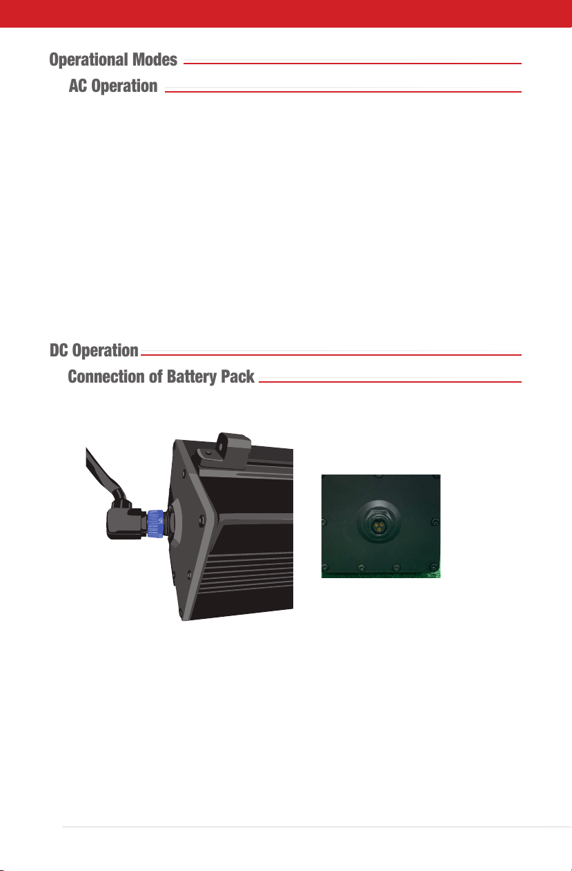
DC Operation .................................................................................................................. 10
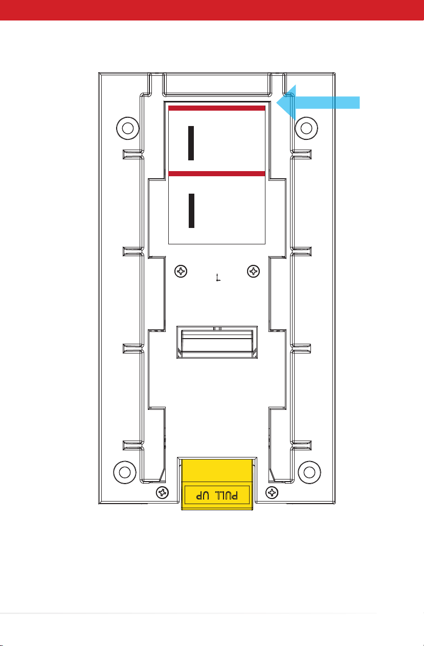
- Connection of Battery Pack ............................................................................ 10-11
- Battery Operation Procedures ...................................................................... 12-13
- Run Time ................................................................................................................ 13
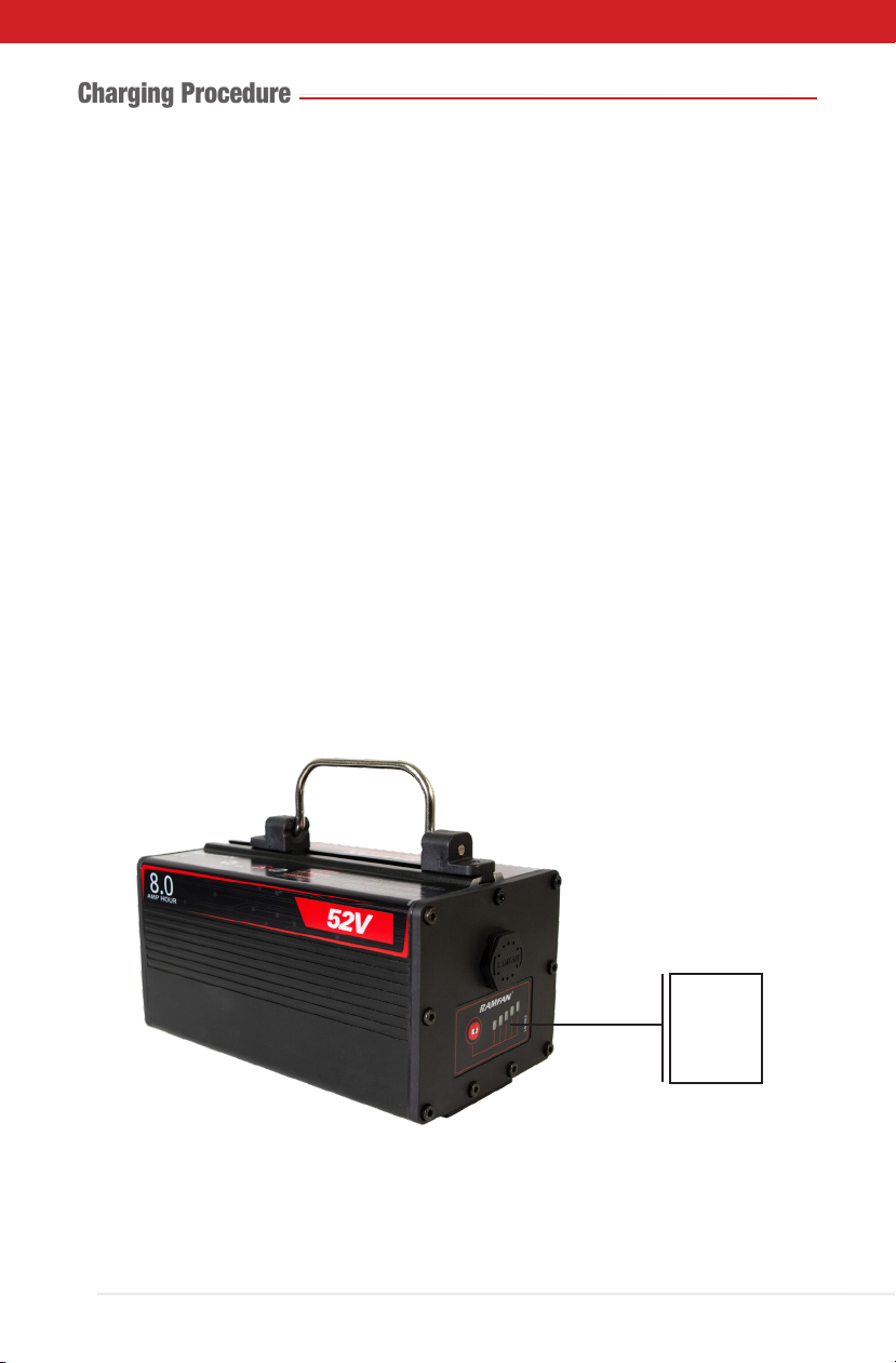
- Charging Procedure .............................................................................................. 14
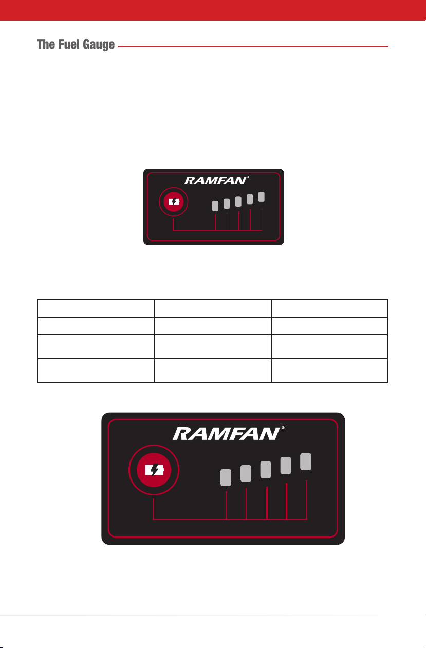
- The Fuel Gauge ..................................................................................................... 15
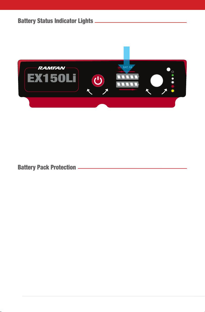
- Status Indicator Lights .......................................................................................... 16
- Battery Pack Protection ....................................................................................... 16
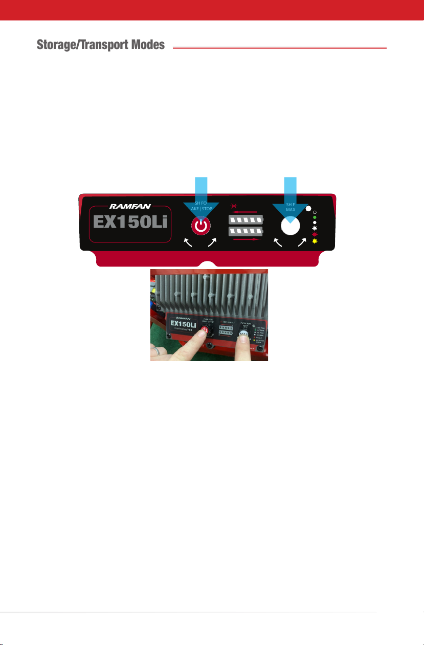
Storage/Transport Modes .......................................................................................................... 17
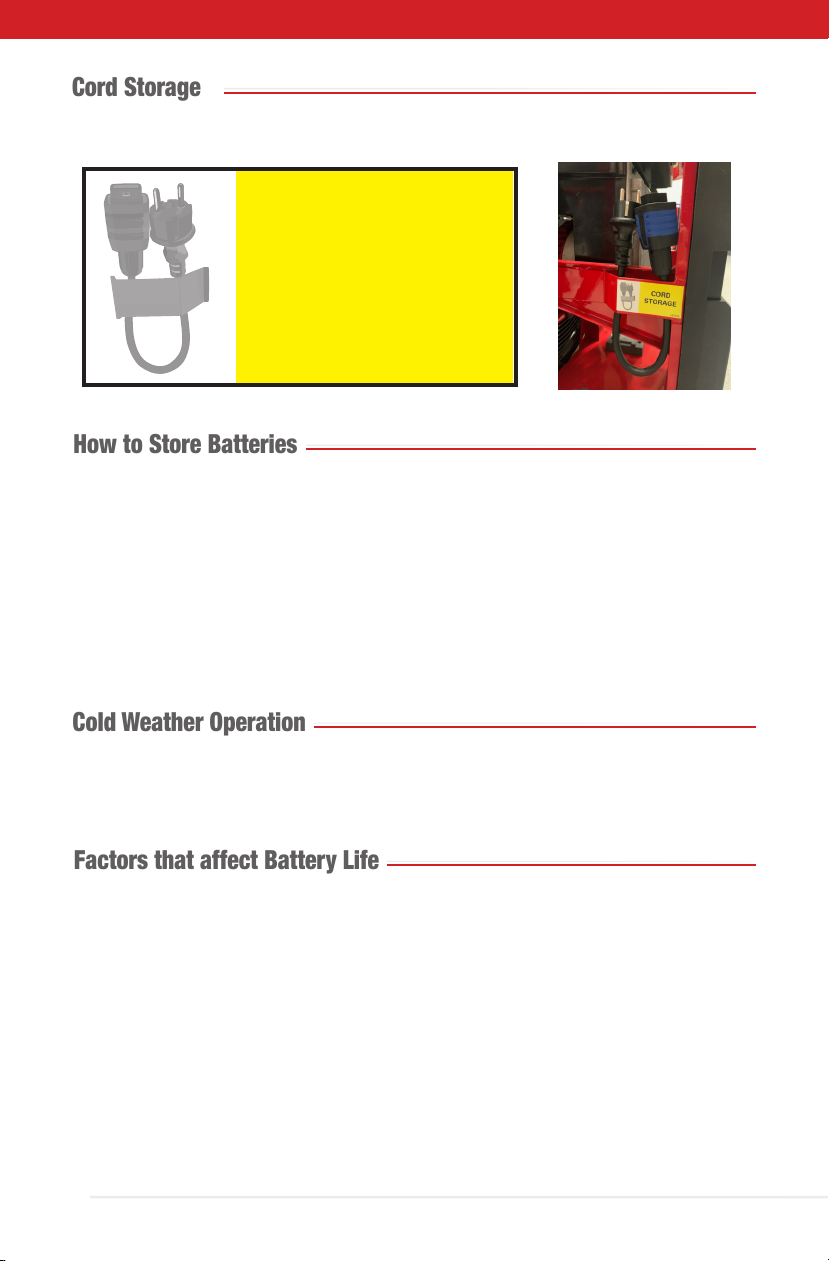
- Cord Storage ......................................................................................................... 18
- How to Store Batteries ......................................................................................... 18
- Cold Weather Operation ...................................................................................... 18
- Factors that aect Battery Life ............................................................................ 18
Maintenance and Disposal ......................................................................................................... 19
Accessories .................................................................................................................................... 19
Certication ................................................................................................................................... 20
Declaration of Conformity ......................................................................................................... 21

3
Introduction
Congratulations on your purchase of the high-end ventilator RAMFAN EX150Li.
WARNING!
Read this manual before starting for the rst time!
You now own an industrial ventilation unit that oers endless possibilities. Before using,
make sure that no damage was done to your ventilator during transport. If this is the case,
do not use the product and immediately contact your authorized Euramco dealer.
For your own safety and that of others, please read this instruction manual carefully before
using the unit.
Anyone involved in installing, operating or servicing the EX150Li must:
• Be a qualied, authorized professional.
• Strictly follow the instructions in this user manual.
Please take the time to read this manual carefully and thoroughly before operating the
ventilator. You should have a good knowledge of its operating conditions and all pertinent
product information.
After you have become familiar with this manual, we recommend that you keep a copy for
future use. All the information found in this manual is subject to change without notice.
Euramco reserves the right to modify and upgrade its range of products, with no obligation
to integrate these changes into products already sold.
If any questions arise concerning any of the information in this manual, Euramco Customer
Service must be consulted:
Euramco Group
2746 Via Orange Way
Spring Valley, CA - 91978
Ph 619.670.9590
Fx 619.670.7345
Toll Free: (800) 472-6326
www.euramco.com
About Euramco
Euramco Group is a leading manufacturer of portable ventilation solutions for the world’s
toughest job sites, with a primary focus on rotating machinery, engineered for superior
uid dynamics, and developing innovative industry-specic drive and control solutions.
Euramco Group sells to defense, reghting, hazardous area, and commercial safety
markets worldwide through ve locations globally.

4
Warning Labels and Safety Instructions
This is the safety-alert symbol.
When you see this symbol on your ventilator or in this manual, be alert to the potential for
personal injury or damage to your equipment. Be sure you understand all safety messages
and always follow recommended precautions and safe operating practices. Important
safety information is presented in this section and throughout the manual:
• Electrical shock hazard. Do not open the unit.
• DO NOT START with signs of visible damage.
• Ventilator is not intended for operation in explosive atmospheres.
• Wear ear protection when close by.
• Keep body parts and loose objects away from in take of ventilator.
• Do not move ventilator while in operation.
• Operate and repair by trained personnel only.
• Always use grounded plug and properly ground AC power receptacle.
• Heat sink becomes hot during charging to some extent. DO NOT touch. Do not place
items over heat sink area.
• Use with approved, good condition extension cord with the ground connector:
Wire Gauge Requirements per ft (m)
0-150 ft (0-50m) AWG 14 (2.5 mm2)
>150 ft (> 50m) AWG 12 (4 mm2)
HOT SURFACE
!
DO NOT TOUCH!
DO NOT PLACE ITEMS OVER
HEAT SINK AREA!
KEEP
FINS
CLEAR
HIGH VOLTAGE
DO NOT OPEN
No User Serviceable Parts
CAUTION!

5
Safety Checklist
√Always purchase from a Euramco's authorized dealer to ensure you are getting real
RAMFAN products, a full product warranty, and the best customer service.
√Flexible electrical cables connected to the equipment may not be used when damaged
√If you are unsure if the equipment is unsafe or if there are signs indicating that the
equipment is defective or damaged, report it and do not use it.
√ Check if the connectors, cables and its connections are in perfect condition.
√Do not use the equipment until the equipment has been fully assembled and
inspected for correct performance in accordance with the Owner's Manual.
√ Fully charge the batteries before the rst use! Safeguard your battery to ensure
continued high performance. It should be recharged after each use.
Unit Description
• The EX150Li is a multi-purpose 18"/46 cm ventilator powered by battery(s) or 90-250V
single phase, 50-60Hz AC power source. Its multipurpose frame can be congured for
PPV, smoke ejector or ducted ventilator use in both normal, horizontal and hanging
positions. The ventilator can be tilted from 0-30° within the frame in PPV mode.
• The motor controller and batteries are water-resistant, IP66 rated.
• The motor is a variable-speed BLDC motor controlled by a microprocessor integrated
with a power supply, dual battery chargers and an LED light driver.
• The EX150Li will run with one or two 52V 8Ah Lithium Ion Battery Packs. The batteries
may be swapped during operation.
• AC voltage can be applied while running on batteries and the ventilator will auto-switch
to AC power. Conversely, the AC power can be removed, and the unit will auto-switch
to battery power, if enough charge remains to power the ventilator.
• The integrated battery chargers will charge one or two fully discharged battery packs in
6 hours or less.
• LED scene lights are integrated into the ventilator shroud and have a 3-intensity
innite switch knob: high, low and o. Turn to change. The LED knob selects the scene
lights output level in a row. Clockwise Progression: O Full Half O.
• A Control Panel on the top of the unit controls all functions.
Parts List
Qty Description
1Ventilator EX150Li with Wheel Kit assembled
2Lithium-ion Battery Pack M1-52V 8Ah
1Power Cord

6
23"
17"
19" 21"
2.3"
4.3"
4.5"
7.8"
Technical Specications
Dimensions
Model EX150Li 18” (46 cm)
Motor 1.9hp (1.4kw)
Order #EL6500 EX150Li with wheel kit assembled (1), 52V 8Ah battery (2) and
power cord (1)
Runtime @ Full speed
DC: 45 min
DC Max: 30 min
AC: Unlimited
AC Input Multiple plug options available
Battery System 52V Lithium-Ion, 832Wh, 16Ah
IP Rating (Motor/
Battery
System/Controller)
IP66 / IP66 / IP66
Weight
2 packs
Without Battery
71 lbs (32 kg)
58 lbs (26 kg)
Dimensions (h x w x d) 23 x 21 x 19 in / 58 x 53 x 48 cm
Approvals
AMCA Vered Airow in
DC Power Supply
12,377 cfm (21,029 m3/hr)
AMCA Vered Airow in
AC Power Supply
11,896 cfm (20,211 m3/hr)

7
Main Interface
Control Panel:
AC PWR
PUSH FOR
WAKE | STOP PUSH FOR
MAX
L
R
DC PWR
DC MAX
FAULT
BAT. FAULT
NO PWR
STORAGE
MODE
Intellisense
TM
E3
LIGHTS SPEED
MAX
1
5
2
6
4
3
Number Symbol Indicate Function
1Wake Button / Emergency Stop Button
Press and hold WAKE button to start.
2Maximum Speed (DC) Button
Press MAX button for 2 seconds.
3LED Scene Lights
On, o, on high or on low.
4Speed Control
Controlled operation from 0 to full speed
5
Battery Status LED Lights
6
Ventilator Status LED Lights
See table below for details.
MAX
MAX
L
R
BAT. FAULT
AC PWR
DC PWR
DC MAX
FAULT
NO PWR
STORAGE
MODE
LIGHTS
SPEED
Color Status Description
O NO PWR Power is o
Green (Solid) AC PWR Ventilator is running on AC Power Supply
White (Solid) DC PWR Ventilator is running on DC Power Supply
White (Flashing) DC MAX Ventilator is running on Maximum speed - DC
Power Supply
Red (Flashing) FAULT Fault on the ventilator
Yellow (Flashing) STORAGE MODE Storage/Transport Mode

8
Plug Types
The EX150Li is suitable for worldwide applications. A voltage converter is not needed. The
unit includes a simple removable cord that allows the unit to operate up to 250 VAC:
Mainly used in Type Order #
USA, Canada, Mexico and
Japan
BEL-CUS-4762
Germany and France (and
most European countries)
E/F EL-CEU-4762
United Kingdom, Ireland,
Malta, Malaysia and
Singapore
GEL-83070-4762
Australia, New Zealand,
Papua New Guinea and
Argentina
IEL-84040-4762
China I EL-84640-4762
If it becomes necessary to use a power cord with another plug standard, order the power
cord that matches the electrical requirements of the country or area. The physical adapter
for the outlet is interchangeable for use in dierent countries and allows you to swap the
cable yourself into the socket.
This is an overview of electric plugs that are in use around the world. If you need a
special solution, just inform your local Euramco representative about the specic.
If you must change the power cord, please disconnect the cord from the electrical outlet
located on the back of the ventilator, as shown below, and replace with another:
How to Install and Remove Power
Cable:
• Cable snaps into place, easy one
hand usage.

9
Adjusting Angle
To adjust the ventilator angle to suit the desired position, unscrew the tilt adjustment knob
and adjust it at the desired angle upwards and then lock it in position by tightening the
knob. The shroud can pivot upwards to a range of 30°.
30°
Tilting Angle
30°
Pull the plug out itself, never by the cord or by wiggling it out of the outlet.

10
Connection of Battery Pack
DC Operation
• Plug the ventilator connector cable (blue) into the battery connector:
• Set the installation index on the battery with the cable, lining up with the cable
connector.
• Press the connector lock and rotate the blue piece clockwise (a quarter turn to the
right) in the most careful way possible.
• Align the edge of the battery pack with holder under the red line where it says, “Align
battery EX150Li” and rmly slide the battery in the direction of the arrow as shown in
the illustration until a loud click is heard.
Operational Modes
• Input Voltage. 90-250VAC, 50/60Hz
• The ventilator is capable of operating seamlessly in countries that supply electricity at
either 120V AC/60 Hz or 240V AC/50 Hz without manual adjustments by the user.
• Operation out of these limits can damage electrical components and will void the
warranty.
1. Connect the fan to an AC power source.
2. Status LED Light will automatically turn green, displaying the status “Ventilator is running
on AC Power Supply”.
3. Start the ventilator by using the Speed Control knob to the desired speed.
Note: You can keep the batteries on their location without charging the battery.
Battery Indicator Lights will turn o because there is no battery charging
when ventilator is running on AC.
4. When the fan is powered o, Status LED Light will automatically turn o after 1 hour and
the battery Indicator Lights will redisplay battery charge level of each battery pack detected.
The ventilator will begin charging the battery packs after 60 minutes of idle time.
5. Battery Packs do not charge while ventilator is running.
AC Operation

11
EX50Li
DATE 08/27/19
ITEM#
LABEL# LB9113
REVISION -
DIMS* 1.5748 x 2.25 in
MATERIAL MainStock: TEC4911 4Mil Vinyl Flex White TC Vinyl UL 50#SCK w/Permanent Adh
COLOR Black, Red
- Label Created 08/27/19
Revision Description Date
HISTORY - LB9113
Example of label placed on batter base
ALIGN
BATTERY
EX150Li
ALIGN
BATTERY
EX50Li
LB9113
ALIGN
BATTERY
EX150Li
ALIGN
BATTERY
EX50Li
LB9113
• Gently pull up the yellow handle to remove the battery from the holder.

12
Battery Operation Procedures
Please full charge battery before rst use
Using One Battery
• The EX150Li allows the option of using one or two battery packs.
• When using one battery, simply plug the battery into either one of the two battery
connectors (left or right).
• Be sure to secure the unused battery connector by placing electrical tape over the
contacts.
• When the system is powered using one battery, the battery indicator light bar on
control panel will only emit light for one battery, when the system is powered on.
Using Two Batteries
• The EX150Li oers a true redundant dual battery system.
• When using two batteries of identical charge level, batteries are connected in parallel to
increase signicantly the total runtime and airow performance.
• When using two battery packs, each pack functions independently and is isolated
from the other so that if one pack should fail (open circuit, short-circuit, or become
discharged) the other battery will provide power to operate the system.
• When using dual batteries, it’s important that both batteries be of the same charge
level and ideally of the same age and condition.
• It’s normal for one battery to discharge slightly more than the other. This is the nature
of a truly redundant isolated battery system.
• The battery that has the higher voltage will discharge at a faster rate (until its voltage
equals the other battery).
• We recommend that use both batteries on the Same State of Charge (or at least as
close as possible). If this is not possible, the controller will eventually bring batteries to
a balanced charge level.
• To keep battery packs healthy for long-term use, a simple implementation of cell-
balancing, internal to the battery pack, includes a FET placed in parallel with each cell
and controlled by a comparator for simple voltage based algorithms that turn-on the
bypass FETs during the onset of voltage dierences, controlled by a microcontroller
for more complex and eective algorithms that can work continuously regardless of
variations of voltage dierences.

13
• When AC is disconnected and Speed Control is o (speed = 0), the controller and
battery(s) will enter a sleep mode to conserve the battery power after 60 minutes of no
activity.
• To wake the ventilator, push and hold WAKE | STOP Button on Control Panel.
Battery Status LED Light will show white solid for the status. The unit will return to
sleep mode if not used within 10 minutes.
• The ventilator starts at the lower speed = 0. Speed will vary by 11 levels - from 11
(highest) to 0 (o). Turn clockwise to increase speed. At level 11 (the highest), if keep
turning the control knob clockwise, the speed will not change, it will stay at highest
speed all the time. To slow down, turn counterclockwise.
• If you want to increase the speed, push and hold the MAX Button Ventilator
Status LED Light will ash white for the status. Remember that this will only work when
2 batteries are connected to the ventilator and when it is operating exclusively on DC
current source (battery).
• The ventilator will operate on one or two battery pack(s). If two battery packs are used
simultaneously, they discharge evenly.
• To STOP the ventilator, push and hold WAKE|STOP Button on Control Panel.
Battery Status LED Light will be unlit.
• Battery(s) may be swapped for charged batteries at any time.
• Reduce run speed to minimum required to increase runtime.
Battery Operation Procedures
MAX
MAX
MAX
Run Time
Run time refers to how long the ventilator on battery power will last under a given load.
We will assume both batteries have full charge beforehand and also 100% eciency (Read
"Factors that aect Battery Life" section):
2 Batteries Speed Level Knob
At maximum speed 45 minutes 11
At maximum speed and DC Max
button activated
30 minutes Max button activated MAX

14
Make sure the battery pack is connect correctly into the ventilator, as described above in
“Connection of Battery Pack”.
• The next step is to leave the ventilator o. During charging, the battery indicator lights
will ash. The battery charge level can be recognized by the number of lights that are
constantly lit.
• If both batteries and AC are connected, the batteries will begin charging after 60
minutes of idle time. If only one single battery is connect, the battery will begin
charging after 120 minutes of idle time.
• Indicator lights will show charge state during charging. Charging should complete in
about 5 hours, with the Battery Status Indicator lights turning green and all the ve
Fuel Gauge lights on the battery turning red. Should the Speed Control be turned
counterclockwise on during the charge, charging will stop, and the ventilator will start.
Charging will begin again after 15 min of idle time.
• After charging is complete, the chargers will maintain the battery(s) by keeping the
ventilator connected to AC.
• While charging, the battery status LED lights will strobe, as well as the battery charge
indicator status lights located on the battery itself. The batteries will be disconnected
at the end of their charge automatically. At the end of charging, the current power is
displayed for 5 minutes and then lights will be turned o.
• If all the Fuel Gauge lights are ashing, this indicates an error condition.
Charging Procedure
Battery
Fuel
Gauge

15
The Fuel Gauge
The Battery Fuel Gauge provides battery status information using ve red LEDs.
Press the Fuel Gauge button to display the lights. The fuel gauge lights will remain lit for
approximately ve seconds.
The numbers represent each LED and the grid is how they're laid out:
12345
Fuel Gauge Lights Diagnosis Solution
LEDs 1-5: Red Solid Remaining Run Time Continue Working
LED 1: Red Flashing
LEDs 2-5: O
Less than 13% run time left Charge Pack
LEDs 1-5: Red Flashing Battery Temperature too
high
Allow Battery to Cool
Less than 13% if bottom light is ashing
35-55%56-76% 77-99% 100%
14-34%

16
Battery Status Indicator Lights
On the control panel there are 2 sets of lights: on the top side of the battery lights indicate
the charge level in the battery attached to the left side of the ventilator, on the bottom side
of the battery lights indicate the charge level in the battery attached to the right side of the
ventilator.
AC PWR
PUSH FOR
WAKE | STOP PUSH FOR
MAX
L
R
DC PWR
DC MAX
FAULT
BAT. FAULT
NO PWR
STORAGE
MODE
Intellisense
TM
E3
LIGHTS SPEED
MAX
If the battery is charging, the green indicator lights will horizontally scroll from left-to- right,
turning solid green when the battery is fully charged.
If the ventilator is running on battery power, the estimated remaining battery time is
shown.
If all the lights ash red, this indicates that the battery has failed and the battery must be
replaced.
Battery Pack Protection
• To protect itself from damage and extend its life, the battery pack's intelligent circuit
monitors current draw and temperature. In extreme situations, the battery pack will
turn OFF the ventilator if the current draw becomes too high. All the fuel gauge lights
will ash.
• Under extreme circumstances, the internal temperature of the battery could become
too high. If this happens, the fuel gauge lights will ash in an alternating pattern and
the tool will not run.
• While a battery undergoes a charge cycle, its temperature rises. To prevent grid
corrosion and eventual battery failure, allow the battery to cool down in between
charging and discharging.

17
Storage/Transport Modes
• Make sure thepower cord is disconnectedbefore activate the Storage/Transport Mode
and 1 or 2 battery pack(s) are connected to the ventilator (atbattery mode).
• To activate Storage/Transport Mode, press and hold theWAKE|STOP and the MAX
buttons at thesame time for 8 seconds or untilthe topStatus LED Light switches to
yellow ash mode (STORAGE MODE).
• Motor automatically runs a very low rpm until it reaches 30% of SoC. Unit will turn o
automatically when it is done. Setting the speed to o will also exit storage/transport
mode.
• The Storage/Transport Function is disabled when the unit is running in AC mode.
Transport Mode (Battery)
All lithium ion cells and batteries must be shipped at a state of charge (SoC) not exceeding
30% of their rated capacity, according to IATA Dangerous Goods Regulations (DGR).
Due to this requirement, the ventilator is equipped with a built-in “Transport Mode”
function.
When this function is activated, the motor automatically runs a very low rpm to let
the battery discharges until it reaches 30% of SoC. The controller monitorsthebattery
voltageand shut down the motor when this SoC level is reached.
Storage Mode (Battery)
The Storage Mode isdesigned to keep your battery maintained during long term storage.
Store lithium batteries at around 30% charge level. The 30 percent charge allows a stable
condition even if it means a level of self-discharge. Some reserve charge is necessary to
keep a battery and its protection circuit operational during long periods of storage.
When Storage Mode is activated, the motor automatically runs a very low rpm to let
the battery discharges until it reaches 30% of SoC. The controller monitorsthebattery
voltageand shut down the motor when this SoC level is reached.
AC PWR
PUSH FOR
WAKE | STOP PUSH FOR
MAX
L
R
DC PWR
DC MAX
FAU LT
BAT. FAULT
NO PWR
STORAGE
MODE
Intellisense
TM
E3
LIGHTS SPEED
MAX

18
Cold Weather Operation
RAMFAN Lithium-Ion battery packs are designed to operate in temperatures below freezing.
A "cold-soaked" battery may not power a unit. To obtain full power, warm up a cold-soaked
battery at room temperature before charging.
Factors that affect Battery Life
• Battery packs will last signicantly longer when run in pairs; there will be a lower amp
draw on each cell.
• Similar to a mechanical device that wears out faster with heavy use, the Depth of
Discharge (DoD) determines the cycle count of the battery. The smaller the discharge
(low DoD), the longer the battery will last. If at all possible, avoid full discharges and
charge the battery more often between uses. Partial discharge on Li-ion is ne. There
is no memory and the battery does not need periodic full discharge cycles to prolong
life. Battery(s) will need to be replaced as they age.
• Keep the ventilator attached to AC while not being used. This will keep them charged
and lengthen their service life. An idle battery will slowly lose charge and possibly
become unusable.
Cord Storage
CORD
STORAGE
After use, store the power cord on the holder on the side of the fan, where there is a
label representation of how to store it:
How to Store Batteries
Temperature range for battery storage:
• Store less than 1 month: -20°C to +60°C (-4°F to +140°F)
• Store less than 3 month: -20°C to +45°C (-4°F to +113°F)
• Store less than 1.5 year : -20°C to +25°C (-4°F to +77°F)
Temperature range for discharge: -20°C to +45°C (-4°F to +113°F)
Temperature range for charge: 0°C to +40°C (+32°F to +104°F)
Maximum non-operational relative humidity for storage: 90% RH

19
Maintenance and Disposal
• DO NOT disassemble the ventilator for maintenance reasons.
• Do not loosen screws on control box without contacting Euramco customer service.
They are torqued to a setting to achieve water tightness. Clean ventilator periodically
to remove accumulated dust or particles from ventilator guards.
• Assembly screws are torqued to a specied value to achieve water tightness.
Completely unravel power cord and place unit on a at, stable surface. Clean ventilator
periodically to remove accumulated dust or particles from ventilator guards, impeller
blade and heat sink in rear of controller (ribbed). Use only biodegradable detergents. If
power washing, avoid controller housing especially gaskets and control panel.
• Contact factory for replacement parts and installation instructions. To order spare
• Always dispose of your battery pack according to federal, state and local regulations.
• Even discharged batteries contain some energy. Before disposing of, use electrical tape
to cover the terminals to prevent the battery pack from short circuit.
• Properly dispose of battery packs when necessary. Contact your local hazardous
materials e-waste collection department for details or proper disposal of rechargeable
batteries.
Accessories
1. Swappable 52V Li-Ion
Battery Pack
Spare Battery (recommend
ordering 2)
Order # M1-52V
4. Hi-Expansion Foam
Adapter
Foam adapter converts EX150Li
into a high expansion foam
generator
Order # HI-X18
2. Vehicle Mount Kit
Custom mount that perfectly ts
ventilator
Order # EL610K
3. EX50Li Mister
Order # EL8111
5. Convert to Conned Space
Rescue Fan
18”/46cm duct (16.4’/5m length)
Order # FDT-185MSR
18”/46cm duct (32.8' / 10m length)
Order # FDT-181MSR
6. Bolt-on Rubber Foot
(Set of 4)
Rubber foot (Set of 4) + Screws for
EX150Li frames

20
Certication
WWW.EURAMCO.COM PROUDLY MADE IN CALIFORNIA
FlowPath™ Control
Euramco Safety Inc.
certifies that the
portable PPV
Blowers shown here
are licensed to bear
the AMCA SEAL.
Euramco Safety Inc. certies that the Portable PPV Blower
shown below is licensed to bear the AMCA Seal. The ratings
shown are based on tests and procedures in accordance with
AMCA Publication 211 and comply with the AMCA Certied
Ratings Program.
Why We Use AMCA
AMCA, The Air Movement and Control Association International,
has been in existence for nearly 80 years and is the world’s only
recognized authority for the development of standards and
measurement of air movement.
Our commitment to AMCA Certication is your veriable assurance that every RAMFAN PPV
Turbo Blower will perform exactly as specied.
Performance certied is for installation type A - Free inlet, Free oulet.
Performance ratings do not include the eects of appurtenances (accessories).
RAMFAN’s re ghting PPV Series outperforms larger blowers in their class with their precision
balanced TurboForce Impellers that maximize airow. These PPV blowers have proven to be eective
in controlling airborne contaminates, replacing interior air, removing heat and supplementing xed
ventilation systems. By pressurizing properly and controlling the resultant ow path, these changes
occur very rapidly. This is accomplished by using these specialized blowers with the power and velocity
to pressurize the interior of a structure or building.
SPECIFICATIONS AND PERFORMANCE RATINGS
2746 Via Orange Way | Spring Valley, CA 91978 USA | (800) 472-6372 | (619) 670-9590
August 2019
AMCA
Euramco Safety Inc.
certifies that the
portable PPV
Blowers shown here
are licensed to bear
the AMCA SEAL.
MODEL SIZE HP DIMENSION (HxWxD) MOTOR
MFG/MODEL NOWEIGHT RPM SETBACK ANGLE AIRFLOW @
FULL SPEED
POWER
SUPPLY
in cm in cm lbs kg ft m tilt cfm m³/hr
EX150Li 18 46 1.8 23x21x19 58x53x48 Euramco EM-E1020 58 26 3550 16 4.9 11˚ 11,896 20,211 AC
EX150Li 18 46 1.8 23x21x19 58x53x48 Euramco EM-E1020 58 26 3600 16 4.9 11˚ 12,377 21,029 DC
Table of contents
Other Euramco Safety Fan manuals