Euresys EureCard PICOLO Tetra User manual

EureCard PICOLO series
PICOLO Tetra, PICOLO Tetra-RC,
PICOLO Tetra-X, PICOLO Tetra-X-RC,
PICOLO Jet-X, PICOLO Jet-X-RC
VEB, VEB 12, MIO
Manual
Copyright ©2005 Euresys s.a.
Liège Science Park
Avenue du Pré-Aily, 14
B-4031 Angleur Belgium
Phone +32 4 367 72 88 • Fax +32 4 367 74 66
Web site: www.euresys.com
This book is part of the documentation
provided with MultiCam.
For more information, refer to the
documentation provided in the latest
MultiCam release.
EureCard Picolo series Manual
Tome 2
January 2005

Copyright ©2005 Euresys s.a.
Printed in Belgium.
WARNING
EURESYS S.A. shall retain all property rights,
title and interest in the hardware or the software,
documentation and trademarks of EURESYS S.A.
All the names of companies and products
mentioned in the documentation may be
the trademarks of their respective owners.
The licensing, use, leasing, loaning, translation,
reproduction, copying or modification of the hardware
or the software, marks or documentation of EURESYS S.A.
contained in this book, is not allowed without prior notice.
EURESYS S.A. may modify the product specifications
or change the information given in this documentation
at any time, in its discretion, and without prior notice.
EURESYS S.A. shall not be liable for any loss of
or damage to revenues, profits, goodwill, data,
information systems or other special, incidental,
indirect, consequential or punitive damages of
any kind arising in connection with the use of
the hardware or the software of EURESYS S.A.
or resulting of omissions or errors in this book.

Table of contents
3
Table of Contents
Part I. Picolo Tetra Product Description............................................................7
1. Product appearance............................................................................................7
2. PCI requirements.................................................................................................8
3. Connectors ..........................................................................................................9
4. Features .............................................................................................................10
5. Picolo Tetra block diagram...............................................................................11
6. Picolo Tetra and Tetra-RC standard compliance............................................12
Part II. Picolo Tetra-X Product Description .................................................... 13
1. Product appearance..........................................................................................13
2. PCI requirements...............................................................................................14
3. Connectors ........................................................................................................15
4. Features .............................................................................................................16
5. Picolo Tetra-X block diagram ...........................................................................18
6. Picolo Tetra-X and Tetra-X-RC standard compliance ....................................19
Part III. Picolo Jet-X Product Description....................................................... 21
1. Product appearance..........................................................................................21
2. PCI requirements...............................................................................................22
3. Connectors ........................................................................................................23
4. Features .............................................................................................................24
5. Picolo Jet-X block diagram...............................................................................26
6. Picolo Jet-X and Jet-X-RC standard compliance............................................27
Part IV. Picolo RC Product Description ........................................................... 29
1. Common characteristics of RC boards ...........................................................29
2. Product appearance of Tetra-RC .....................................................................30
3. Product appearance of Tetra-X-RC..................................................................31
4. Product appearance of Jet-X-RC .....................................................................32
5. PCI requirements...............................................................................................33
6. Connectors ........................................................................................................33
7. 75 ohms solder bridges ....................................................................................34
8. Block diagrams..................................................................................................35
9. Video input routing ...........................................................................................38
Part V. VEB and VEB 12 Product Description................................................ 41
1. Product appearance..........................................................................................41
2. Connectors ........................................................................................................43
3. Features .............................................................................................................44
4. Video input/output routing ...............................................................................45
5. VEB and VEB 12 standard compliance ...........................................................48
Part VI. MIO Module Product Description ...................................................... 49
1. Product appearance..........................................................................................49
2. Connectors ........................................................................................................50
3. Features .............................................................................................................51
4. MIO standard compliance.................................................................................52

Table of contents
4
Part VII. Hardware Installation Procedure ...................................................... 53
1. Warnings............................................................................................................53
2. Hardware installation procedure......................................................................54
3. Picolo RC series hardware installation ...........................................................56
4. Input Video Expansion Bracket hardware installation...................................57
5. Output Video Expansion Bracket hardware installation................................57
6. MIO hardware installation.................................................................................58
Part VIII. MultiCam Installation Guide ............................................................. 61
1. Hardware requirements ....................................................................................61
2. Linux installation...............................................................................................61
3. Windows installation.........................................................................................62
Part IX. Technical Specifications .................................................................... 63
1. Technical specifications for all Picolo products ............................................63
2. Picolo Tetra series technical specifications ...................................................65
3. Picolo Jet-X technical specifications ..............................................................67
4. MIO technical specifications ............................................................................69
Contact Us
5
Contact Us
Euresys
Web site: www.euresys.com
America Asia Japan Europe
Euresys s.a. Japan Euresys s.a.
Euresys inc. Euresys Pte. Ltd.
Representative Office Corporate Headquarters
500 Park Boulevard
Suite 525
627A Aljunied Road
#08-09 BizTech Centre
AIOS Hiroo Building 8F,
Hiroo 1-11-2, Avenue du Pré-Aily, 14
Itasca, Illinois 60143,
U.S.A. Singapore 389842
Shibuya-ku,
Tokyo 150-0012,
Japan
B-4031 Angleur,
Belgium
America
Toll free:
Phone:
Fax:
+1 866-EURESYS
+1 630 250 2300
+1 630 250 2301
Asia
Phone:
Fax:
+65 6748 0085
Japan
Phone:
Fax:
+81 3 5447 1256
Europe
Phone:
Fax:
+32 4 367 72 88

This page is intentionally left blank.

Picolo Tetra Product Description
7
Part I. Picolo Tetra Product Description
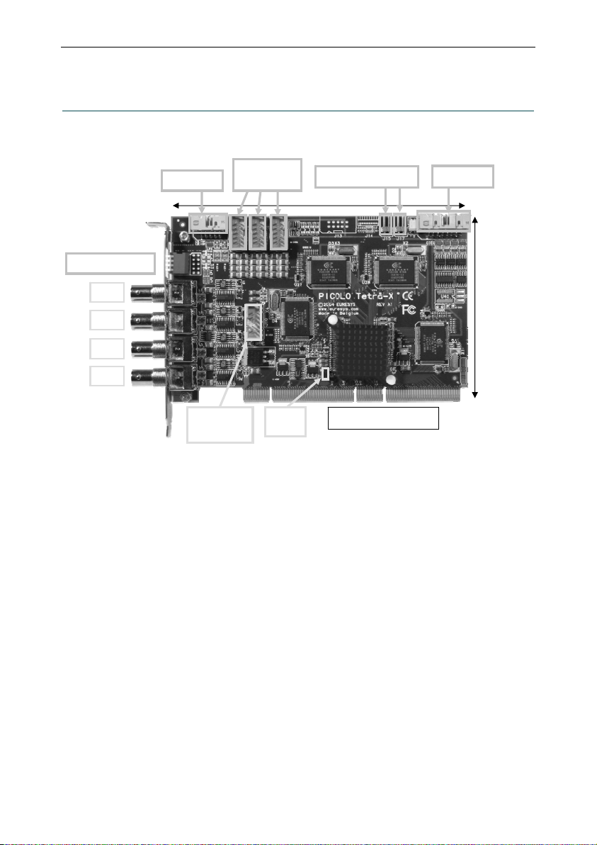
1. Product appearance
Picolo Tetra is a 64-bit, 66 MHz PCI capture board including four color video digitizers. This Picolo board acquires four
real-time video signals in parallel. It may be extended to manage 16 cameras.
Expansion accessories are identical for Picolo Tetra series. Video Expansion Bracket and Video Expansion Bracket 12
are presented in part V. MIO module is described in part VI.
168 mm / 6.61 in
Wide PCI bus connector
107 mm /
4.21 in
VID1
VID3
VID4
75 ohms switches
VEB LINK
(video out)
MIO LINK Digital IO
PC reset headers
VEB LINK
(video in)
1 2 3
VID2

Picolo Tetra Product Description
8
2. PCI requirements
PCI stands for "Peripheral Component Interconnect" and refers to standardized means to install an add-on board
inside a computer.
Picolo Tetra is a medium-size PCI card to be inserted in a standard PCI slot inside a PC. The PCI edge connector is
compliant with the official PCI specification, revision 2.2. It is 64-bit wide, operates at 66 MHz maximum, and supports
3.3 V or 5 V signaling systems.
Picolo Tetra can be used in a 33 MHz or 66 MHz PCI slot and using the PCI slot with 32-bit or 64-bit.
For more information, see “PCI Bus Variation” application note.
Picolo Tetra uses the +5 V, +12 V and -12 V power supply rails provided by the PCI bus.
Typical electrical consumption is as follows:
PCI power rail Current Power
+5 V 1.3 A 6.5 W
+12 V 0.12 A 1.44 W
-12 V 5 mA 0.06 W
Total power consumption is typically 8 W.
Notes:
1. Video Expansion Bracket and Video Expansion Bracket 12 do not consume any power.
2. These PCI characteristics do also apply to Picolo Tetra-RC.
Picolo Tetra Product Description
9
3. Connectors
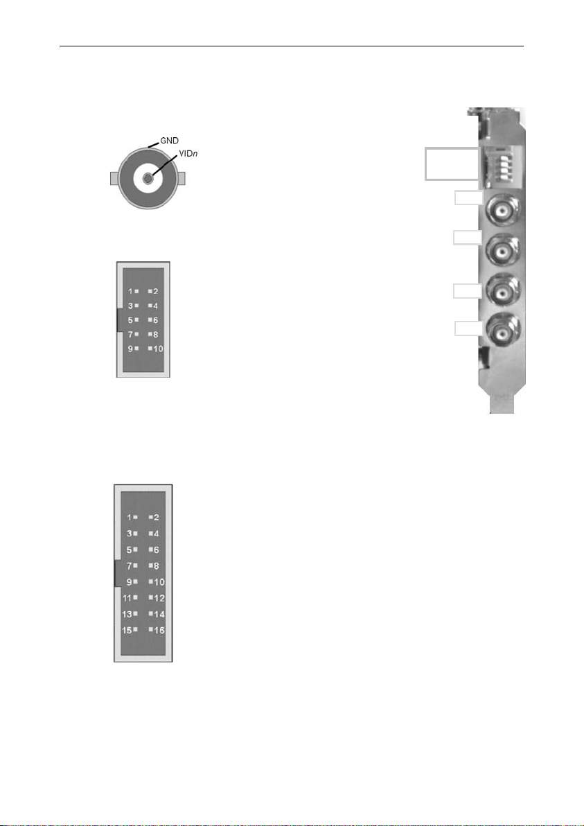
3.1. “VIDn” connector
VID1, VID2, VID3 and VID4 are selectable
color or monochrome composite inputs.
They are terminated with removable
75 ohms loads.
To modify the 75 ohms termination setting,
see “75 ohms switches”.
3.2. “VEB LINK” connectors
Each 10-pin header connector allows to connect one
Video Expansion Bracket with a Picolo Tetra.
Three VEB LINK connectors are used to add video
inputs to a Picolo Tetra. For more details, see “Video
input routing”.
One VEB LINK connector is used for video outputs of
digitalized images. For more details, see “Video output
routing”.
Notes:
1. Each video differential pair is composed of VIDnand GNDn, both connected to digitizer n
where n= 1, 2, 3 or 4.
2. To inform the system of the Video Expansion Bracket existence, simply short-circuit pin 9
“Presence” with pin 10 “Dig. GND”, digital ground of a Picolo Tetra.
3.3. “Digital IO” connector
The “Digital IO” internal connector on the Picolo Tetra has 13
TTL I/O lines that can be used by the MultiCam software
driver as inputs, outputs or trigger lines.
Other Euresys video capture boards use the same connector.
3.4. “MIO LINK” connector
Using flat cables, this 10-pin header connector allows to interconnect a Picolo Tetra to MIO modules.
For more details, see “MIO hardware installation” in part VII.
Reserved
IO1
IO3
IO5
IO7
IO9
IO11
IO13
GND
IO2
IO4
IO6
IO8
IO10
IO12
GND
VID1
VID3
VID2
VID4
75 ohms
switches
1 2 3 4
VID1
VID2
VID3
VID4
Presence
GND1
GND2
GND3
GND4
Dig. GND

Picolo Tetra Product Description
1
0
4. Features
4.1. PC reset headers
Picolo
Tetra
64-bit board
PCI slot
Picolo
Tetra
A reset cable can be connected directly to a "PC
reset header". The watchdog uses a static switch
with an ON resistance of about 35 ohms. The
polarity at the switch input doesn't matter.
In the drawing is illustrated the control of PC reset
by button or by the Picolo Tetra. The switch can
also be used for other purposes than resetting the
computer: for example, it can activate an alarm.
The two "PC reset headers" are equivalent.
See also topic "Using the watchdog" in the electronic documentation.
4.2. 75 ohms switches
OFFON
1 2 3 4
The switch ncontrols the 75 ohms termination of the
corresponding VIDninput, where n= 1, 2, 3 or 4.
In the factory configuration, all video terminations are active.
Therefore, all switches are closed (ON position).
To remove the termination, set the switch to OFF position.
Picolo Tetra Product Description
11
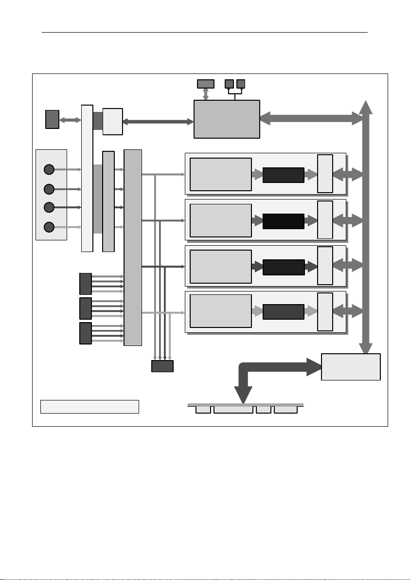
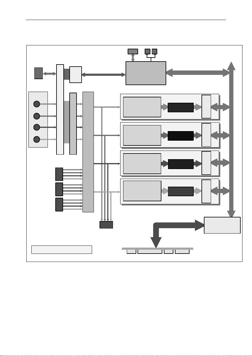
5. Picolo Tetra block diagram
Picolo Tetra Block Diagram
MIO LINK PC reset
headers
PCI control
PIO
Parallel
interface
Video
Common-mode noise removal
Connectors on bracket
VID 1
VID 2
VID 3
VID 4
Transparent
PCI bridge
64 bits, 66 MHz
Digital IO
V
EB LINK
(video in)
V
EB LINK
(video out)
Electromagnetic compatibility network
PCI connector
FIFO buffer 1
630 bytes
PCI
interface
with color decoding,
scaling,
format conversion
Digitizer 1
PCI
interface
FIFO buffer 2
630 bytes
with color decoding,
scaling,
format conversion
Digitizer 2
FIFO buffer 3
630 bytes
PCI
interface
with color decoding,
scaling,
format conversion
Digitizer 3
FIFO buffer 4
630 bytes
PCI
interface
with color decoding,
scaling,
format conversion
Digitizer 4
1
2
3
Quadruple 4-to-1 analog router
Embedded PCI bus
Video input/output routing
The detailed routing is presented in part V, “VEB and VEB12 Product Description”.
Picolo Tetra Product Description
12
6. Picolo Tetra and Tetra-RC standard compliance
This equipment has been tested and found to comply with the limits for a Class B digital device, pursuant to Part 15 of
the FCC Rules.
These limits are designed to provide reasonable protection against harmful interference in a residential installation or
when the equipment is operated in a commercial environment.
This equipment generates, uses and can radiate radio frequency energy and, if not installed and used in accordance
with the instructions, may cause harmful interference to radio communications. However, there is no guarantee that
interference will not occur in a particular installation.
If this equipment does cause harmful interference to radio or television reception, which can be determined by turning
the equipment off and on, the user is encouraged to try to correct the interference by one or more of the following
measures:
•Reorient or relocate the receiving antenna.
•Increase the separation between the equipment and receiver.
•Connect the equipment into an outlet on a circuit different from that to which the receiver is connected.
•Consult the dealer or an experienced radio/TV technician for help.
This equipment has been tested and found to comply with EN55022/CISPR22 and EN55024/CISPR24. To meet EC
requirements, shielded cables must be used to connect a peripheral to the card. This product has been tested in a
typical class B compliant host system. It is assumed that this product will also achieve compliance in any class B
compliant unit.
Concerning video inputs, this equipment has been tested and found to comply with the following tests described in
EN50130-4:
•§ 10, radiated RF immunity ;
•§ 11, conducted RF immunity ;
•§ 12, fast transient immunity.
Notice for USA
Compliance Information Statement (Declaration of Conformity Procedure) DoC
FCC Part 15
Notice for Europe
This product is in conformity with the Council Directive 89/336/EEC amended by
92/31/EEC and 93/68/EEC
Notice for Europe
Standard EN50130-4, immunity requirements for components of fire, intruder and
social alarm systems
Picolo Tetra-X Product Description
1
3
Part II. Picolo Tetra-X Product Description
1. Product appearance
Picolo Tetra-X includes:
•A PCI-X bridge that doubles the throughput compared with Picolo Tetra. The usage of a PCI-X slot is
mandatory to achieve this performance.
•An optimized internal PCI bus between digitizers and PCI-X bridge.
Picolo Tetra-X can be used in PCI-X 66MHz, 100 MHz or 133 MHz slots. It also works in standard PCI slots, 32-bit or
64-bit, up to 66 MHz, 3.3 V or 5 V.
Starting with board revision A1_1, the PCI-X jumper is removed.
Expansion accessories are identical for Picolo Tetra series. Video Expansion Bracket and Video Expansion Bracket 12
are presented in part V. MIO module is described in part VI.
168 mm / 6.61 in
PCI-X bus connector
107 mm /
4.21 in
VID1
VID3
VID2
VID4
75 ohms switches
VEB LINK
(video out)
MIO LINK Digital IO
PC reset headers
VEB LINK
(video in)
1 2 3
PCI-X
jumper

Picolo Tetra-X Product Description
14
2. PCI requirements
PCI stands for "Peripheral Component Interconnect" and refers to standardized means to install an add-on board
inside a computer.
Picolo Tetra-X is a medium-size PCI card to be inserted in a PCI-X slot inside a PC. The PCI edge connector is
compliant with the official PCI specification, revision 2.3 and PCI-X addendum revision 1.0. It is 64-bit wide, operates
at 133 MHz maximum, and supports 3.3 V or 5 V signaling systems.
Picolo Tetra-X can be used in a 66MHz, 100 MHz or 133 MHz PCI-X slot.
Picolo Tetra-X can be used in a 33 MHz or 66 MHz PCI slot and using the PCI slot with 32-bit or 64-bit.
For more information, see “PCI Bus Variation” application note.
Picolo Tetra-X uses the +5 V, +12 V and -12 V power supply rails provided by the PCI bus.
Typical electrical consumption is as follows:
PCI power rail Current Power
+5 V 1.5 A 7.5 W
+12 V 0.12 A 1.44 W
-12 V 5 mA 0.06 W
Total power consumption is typically 9 W.
Notes:
1. Video Expansion Bracket and Video Expansion Bracket 12 do not consume any power.
2. These PCI characteristics do also apply to Picolo Tetra-X-RC.

Picolo Tetra-X Product Description
1
5
3. Connectors
3.1. “VIDn” connector
VID1, VID2, VID3 and VID4 are
selectable color or monochrome
composite inputs. They are
terminated with removable 75 ohms
loads.
To modify the 75 ohms termination
setting, see “75 ohms switches”.
3.2. “VEB LINK” connectors
Each 10-pin header connector allows to connect
one Video Expansion Bracket with a Picolo
Tetra-X.
Three VEB LINK connectors are used to add
video inputs to a Picolo Tetra-X. For more
details, see “Video input routing” in part V.
One VEB LINK connector brings back the 4
video signals being digitized. For more details,
see “Video output routing” in part V.
Notes:
1. Each video differential pair is composed of VIDn and GNDn, both connected to digitizer n
where n= 1, 2, 3 or 4.
2. To inform the system of the Video Expansion Bracket existence, simply short-circuit pin 9
“Presence” with pin 10 “Dig. GND”, digital ground of a Picolo Tetra-X.
3.3. “Digital IO” connector
The “Digital IO” internal connector on the
Picolo Tetra-X has 13 TTL I/O lines that can
be used by the MultiCam software driver as
inputs, outputs or trigger lines.
Other Euresys video capture boards use the
same connector.
3.4. “MIO LINK” connector
Using flat cables, this 10-pin header connector allows to interconnect a Picolo Tetra-X to MIO modules.
For more details, see “MIO hardware installation” in part VII.
Reserved
IO1
IO3
IO5
IO7
IO9
IO11
IO13
GND
IO2
IO4
IO6
IO8
IO10
IO12
GND
VID1
VID3
VID2
VID4
75 ohms
switches
1 2 3 4
VID1
VID2
VID3
VID4
Presence
GND1
GND2
GND3
GND4
Dig. GND

Picolo Tetra-X Product Description
1
6
4. Features
4.1. PC reset headers
Picolo
Tetra
64-bit board
PCI slot
Picolo
Tetra
A reset cable can be connected directly to a "PC
reset header". The watchdog uses a static switch
with an ON resistance of about 35 ohms. The
polarity at the switch input doesn't matter.
In the drawing is illustrated the control of PC reset
by button or by the Picolo Tetra. The switch can
also be used for other purposes than resetting the
computer: for example, it can activate an alarm.
The two "PC reset headers" are equivalent.
See also topic "Using the watchdog" in the electronic documentation.
4.2. 75 ohms switches
OFFON
1 2 3 4
The switch ncontrols the 75 ohms termination of the
corresponding VIDninput, where n= 1, 2, 3 or 4.
In the factory configuration, all video terminations are active.
Therefore, all switches are closed (ON position).
To remove the termination, set the switch to OFF position.
Picolo
Tetra-X

Picolo Tetra-X Product Description
17
4.3. PCI-X jumper
Picolo Tetra-X is compatible with all PCI and PCI-X slots. Initial production boards (rev. A1_0) include a PCI-X jumper.
If present, the factory setting of this jumper is shorted.
Remove the PCI-X jumper if you intend to insert Picolo Tetra-X in a conventional PCI slot.
PCI slot category PCI-X jumper
Conventional PCI
open
PCI-X
shorted
PCI-X
jumper
Picolo Tetra-X Product Description
1
8
5. Picolo Tetra-X block diagram
Picolo Tetra-X Block Diagram
MIO LINK PC reset
headers
PCI control
PIO
Parallel
interface
Video
Common-mode noise removal
Connectors on bracket
VID 1
VID 2
VID 3
VID 4
Digital IO
V
EB LINK
(video in)
V
EB LINK
(video out)
Electromagnetic compatibility network
64 bits, 133 MHz
PCI-X connector
FIFO buffer 1
630 bytes
PCI
interface
with color decoding,
scaling,
format conversion
Digitizer 1
PCI
interface
FIFO buffer 2
630 bytes
with color decoding,
scaling,
format conversion
Digitizer 2
FIFO buffer 3
630 bytes
PCI
interface
with color decoding,
scaling,
format conversion
Digitizer 3
FIFO buffer 4
630 bytes
PCI
interface
with color decoding,
scaling,
format conversion
Digitizer 4
1
2
3
Quadruple 4-to-1 analog router
Transparent
PCI-X bridge
Embedded PCI bus
Video input/output routing
The detailed routing is presented in part V, “VEB and VEB12 Product Description”.

Picolo Tetra-X Product Description
1
9
6. Picolo Tetra-X and Tetra-X-RC standard compliance
This equipment has been tested and found to comply with the limits for a Class B digital device, pursuant to Part 15 of
the FCC Rules.
These limits are designed to provide reasonable protection against harmful interference in a residential installation or
when the equipment is operated in a commercial environment.
This equipment generates, uses and can radiate radio frequency energy and, if not installed and used in accordance
with the instructions, may cause harmful interference to radio communications. However, there is no guarantee that
interference will not occur in a particular installation.
If this equipment does cause harmful interference to radio or television reception, which can be determined by turning
the equipment off and on, the user is encouraged to try to correct the interference by one or more of the following
measures:
•Reorient or relocate the receiving antenna.
•Increase the separation between the equipment and receiver.
•Connect the equipment into an outlet on a circuit different from that to which the receiver is connected.
•Consult the dealer or an experienced radio/TV technician for help.
This equipment has been tested and found to comply with EN55022/CISPR22 and EN55024/CISPR24. To meet EC
requirements, shielded cables must be used to connect a peripheral to the card. This product has been tested in a
typical class B compliant host system. It is assumed that this product will also achieve compliance in any class B
compliant unit.
Concerning video inputs, this equipment has been tested and found to comply with the following tests described in
EN50130-4:
•§ 10, radiated RF immunity ;
•§ 11, conducted RF immunity ;
•§ 12, fast transient immunity.
Notice for USA
Compliance Information Statement (Declaration of Conformity Procedure) DoC
FCC Part 15
Notice for Europe
This product is in conformity with the Council Directive 89/336/EEC amended by
92/31/EEC and 93/68/EEC
Notice for Europe
Standard EN50130-4, immunity requirements for components of fire, intruder and
social alarm systems

This page is intentionally left blank.
This manual suits for next models
8
Table of contents
Other Euresys PCI Card manuals

Euresys
Euresys Coaxlink Mono User manual

Euresys
Euresys 1840 Picolo HD One User manual

Euresys
Euresys Coaxlink Mono User manual

Euresys
Euresys 1630 Coaxlink Mono User manual

Euresys
Euresys Picolo Series User manual

Euresys
Euresys eGrabber 1630 Coaxlink Mono User manual

Euresys
Euresys Grablink Value User manual
Popular PCI Card manuals by other brands


GEFRAN-SIEI
GEFRAN-SIEI ARTDriveG EXP-D6A1R1-AGy instruction manual

StarTech.com
StarTech.com PEX8S1052 instruction manual

SMC Networks
SMC Networks ELITECONNECT SMC2512W-B Specifications

Lava
Lava SSerial-PCI/LP installation manual

Cables to Go
Cables to Go 29055 user guide

Moxa Technologies
Moxa Technologies CP-112UL series Quick installation guide


