GEFRAN-SIEI ARTDriveG EXP-D6A1R1-AGy User manual

...... Manuale Istruzione
Instruction Manual
ARTDriveG
Expansion card
EXP-D6A1R1-AGy

Vi ringraziamo per avere scelto questo prodotto Gefran Siei.
aiutarci a migliorare questo manuale.
Durante il suo periodo di funzionamento conservate il manuale in un luogo sicuro e a disposizione
del personale tecnico.
Il costruttore. si riserva la facoltà di apportare modifiche e varianti a prodotti, dati, dimensioni, in
qualsiasi momento senza obbligo di preavviso.
I dati indicati servono unicamente alla descrizione del prodotto e non devono essere intesi come
proprietà assicurate nel senso legale.
Tutti i diritti riservati.
Thank you for choosing this Gefran Siei product.
We will be glad to receive any possible information which could help us improving this manual.
Keep the manual in a safe place and available to engineering and installation personnel during
the product functioning period.
The manufacturer has the right to modify products, data and dimensions without notice.
The data can only be used for the product description and they can not be understood as legally
stated properties.
All rights reserved

Sommario - Table of Contents
Italiano _____________________________ 4
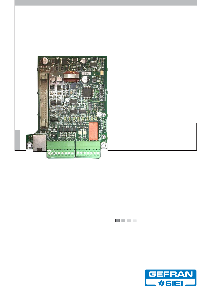
Capitolo 1 - Introduzione ........................................................... 4
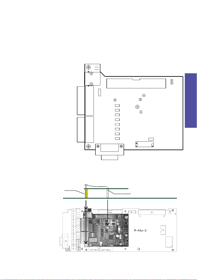
Capitolo 2 - Fissaggio e connessione ....................................... 4
2.1 Connessione ingressi digitali ................................................................ 5
2.2 Connessione uscite digitali ................................................................... 5
2.3 Connessione uscita analogica .............................................................. 6
Capitolo 3 - Alimentazioni ......................................................... 6
3.1 Alimentazione esterna per uscite ingressi e digitali ............................. 6
Capitolo 4 - Ponticelli ................................................................ 6
Capitolo 5 - LED ......................................................................... 7
Capitolo 6 - Funzioni supplementari .......................................... 7
Capitolo 7 - Selezione opzione da AGy ...................................... 7
Capitolo 8 - Caratteristiche tecniche ........................................ 7
8.1 Caratteristiche generali ........................................................................ 7
8.2 Ingressi digitali ..................................................................................... 7
8.3 Uscite digitali ........................................................................................ 8
8.4 Uscite digitali a relè .............................................................................. 8
8.5 Uscite analogiche ................................................................................. 8
8.5.1 Selezione uscita in tensione ....................................................................... 8
8.5.2 Selezione uscita in corrente ....................................................................... 8
English______________________________ 9
Chapter 1 - Introduction ............................................................ 9
Chapter 2 - Fixing and connection ............................................ 9
2.1 Digital input connection ...................................................................... 10
2.2 Digital output connection ................................................................... 10
2.3 Analog output connection .................................................................. 11
Chapter 3 - Power supply ........................................................ 11
3.1 External power supply for digital inputs and outputs .......................... 11
Chapter 4 - Jumpers ................................................................ 11
Chapter 5 - LEDs ...................................................................... 12
Chapter 6 - Additional functions ............................................. 12
Chapter 7 - Option selection via AGy ...................................... 12
Chapter 8 - Technical features ................................................ 12
8.1 General features ................................................................................. 12
8.2 Digital inputs ...................................................................................... 12
8.3 Digital outputs .................................................................................... 13
8.4 Relay digital outputs ........................................................................... 13
8.5 Analog outputs ................................................................................... 13
8.5.1 Selection of the voltage output ................................................................ 13
8.5.2 Selection of the current output ................................................................ 13

—————— EXP-D6A1R1-AGy ——————
4
Italiano
Capitolo 1 - Introduzione
La EXP-D6A1R1-AGy è una delle schede di espansione per i driveAGy che
usano la scheda di regolazione R-AGY o R-AGY2.
La scheda di espansione è composta da:
- 4 ingressi digitali optoisolati 15 ... 30V DC
- 2 uscite digitali optoisolate 15 ... 30V DC 50mA max
- 1 uscita digitale a relè con contatto di scambio 250V AC 5A max
- 1 uscita analogica in tensione (0 ... 10V) oppure in corrente (0 ... 20mA
o 4 ... 20mA)
Figura 1: scheda EXP-D6A1R1-AGy
XR
M1
M2
S4
XPRG
XS
IN1
IN2
IN3
IN4
OUT1
OUT2
NO
NC S3
XOPT
S1
S2
Capitolo 2 - Fissaggio e connessione
Figura 2: fissaggio della scheda di espansione
B (n.1)
C (n.2)
A (n.2)

5
—————— Scheda espansione ——————
Italiano
LaschedaEXP-ENC-AGyvienefornitacon un kit comprendente 2 distanziali
in ottone (A), 1 distanziale in plastica (B) e 2 viti (C) per il fissaggio alla
scheda di regolazione.
1. Spegnere l’azionamento.
2. Toglierela copertura del drive come indicato nel capitolo 5.1 del Manuale
Istruzioni fornito con il drive.
3. Posizionare i distanziali (A e B) sulla scheda di regolazione (vedere
figura2),inserireil connettoreXR (schedadiespansione)nelconnettore
femmina JP13A (nel caso di regolazione R-AGY) o XEXP (nel caso di
regolazione R-AGY2). Su questo connettore sono presenti le
alimentazioni e i segnali.
4. Fissare la scheda con le viti (C).
5. Accendere l’azionamento.
2.1 Connessione ingressi digitali
I 4 ingressi digitali optoisolati hanno un solo comune e possono essere
usati in modalità NPN o PNP. Nella modalità PNP collegare lo 0V
dell’alimentazione al segnale COM e l’interruttore tra il segnale DI EXP n e
il positivo dell’alimentazione. Nella modalità NPN collegare il positivo
dell’alimentazione al segnale COM e l’interruttore tra il segnale DI EXP n e
lo 0V dell’alimentazione.
AGy (standard)
Connettore
Morsetto 4 5 8
Segnale DI 1 DI 2 COM
Parametro drive IPA I.050 IPA I.051
tab 1
INGRESSI DIGITALI (AGy standard)
M1
IPA I.052
6
DI 3
7
DI 4
IPA I.053
AGy L (LIFT)
Connettore
Morsetto 4 5 8
Segnale DI EXP 1 DI EXP 2 COM
Parametro drive (*) IPA I.000…I.012
= [10] DI EXP 1
IPA I.000…I.012
=[11]DIEXP2
tab 1 lift
INGRESSI DIGITALI (AGy L - LIFT)
M1
67
DI EXP 3 DI EXP 4
IPA I.000…I.012
= [12] DI EXP 3
IPA I.000…I.012
= [13] DI EXP 4
(*) La funzionalità degli ingressi digitali espansi è definita dai parametri
I.000 ... I.012
Esempio:per impostareDIEXP1come“Freqsel 1 src”, selezionare
IPA I.003 = [10].
Vedere il manuale AGy-L, Capitolo 12 Lista Parametri - menu INTERFACE.
2.2 Connessione uscite digitali
Vengono considerate uscite digitali sia le uscitedigitalioptoisolatechel’uscita
a relè.
Leuscitedigitalioptoisolatesonocompletamenteseparatee possono essere
usate in modalità NPN o PNP. Nella modalità NPN collegare lo 0V
dell’alimentazione al segnale OUTn- e il carico tra il segnale OUTn+ e il
positivodell’alimentazione.Nellamodalità PNPilpositivo dell’alimentazione
al segnale OUTn+ e il carico tra il segnale OUTn- e lo 0V dell’alimentazione.

—————— EXP-D6A1R1-AGy ——————
6
Italiano
Connettore
Morsetto 9 10 11 12 13 14 15
Segnale OUT1- OUT1+ OUT2- OUT2+ NO NC COM
Parametro drive
tab 2
USCITE DIGITALI
IPA I.150 IPA I.151 IPA I.152
M1
2.3 Connessione uscita analogica
L’uscita analogica può essere usata in tensione o in corrente. La selezione
vieneeffettuata attraverso il ponticello S4posizionatoimmediatamentedietro
i morsetti dell’uscita analogica. Spostando il jumper a sinistra l’uscita è in
tensione mentre verso destra è in corrente. Una serigrafia riassume la
modalità con i simboli “V” e “I”.
Connettore
Morsetto
Segnale
Parametro drive
tab 3
SHIELD OUT ANA1 COM
IPAs I.350 ... I.353
USCITE ANALOGICHE IN TENSIONE E CORRENTE
M2
12 3
Capitolo 3 - Alimentazioni
La scheda richiede l’alimentazione digitale (0V, +5V), analogica (0V, ±15V)
che vengono generate a bordo scheda partendo dalla tensione 24V
proveniente dalla regolazione. Inoltre richiede l’alimentazione per ingressi e
uscite digitali optoisolati che vengono fornite esternamente.
3.1 Alimentazione esterna per uscite ingressi e digitali
L’alimentazione per le uscite digitali serve per alimentare l’uscita
dell’optoisolatore e accetta un range di 15 ... 30V DC. La corrente
dell’alimentatoredeve essere sufficiente al consumo del carico che si applica
alle uscite.
L’alimentazione per gli ingressi digitali serve per alimentare l’ingresso degli
optoisolatori. Ogni ingresso assorbe circa 6mA a 24V.
Capitolo 4 - Ponticelli
La tabella seguente descrive i ponticelli presenti sulla scheda.
Nome
tab 4
Descrizione
“I” Uscita analogica in corrente
“V” Uscita analogica in tensione “V”
Default
Ponticelli scheda EXP-D6A1R1-AGY
S4

7
—————— Scheda espansione ——————
Italiano
Capitolo 5 - LED
Sono presenti 8 led. Hanno la funzione di indicare lo stato di funzionamento
degli I/O digitali. La tabella seguente descrive le indicazioni dei led.
Nome led
IN 1
IN 2
IN 3
IN 4
OUT 1
OUT 2
NO
NC
tab 5
Contatto normalmente chiuso del relè attivo.
Segnalazione
Ingresso digitale 1 attivo.
Ingresso digitale 2 attivo.
Ingresso digitale 3 attivo.
Ingresso digitale 4 attivo.
Uscita digitale 1 attiva.
Uscita digitale 2 attiva.
Contatto normalmente aperto del relè attivo.
Capitolo 6 - Funzioni supplementari
Sulla scheda è presente il connettore XOPT. La sua funzione è prevista
solo per sviluppi futuri.
Capitolo 7 - Selezione opzione da AGy
L’inverter AGy ha la possibilità di collegare due opzioni.
L’abilitazionedelle opzioni avvienetramite i parametri I.700e I.701.La scheda
EXP-D6A1R1-AGY deve essere configurata esclusivamente come opzione
1 con il parametro I.700. Per abilitarla occorre scrivere il codice “2” del
parametro I.700. Per i particolari vedere manuale AGy.
Capitolo 8 - Caratteristiche tecniche
8.1 Caratteristiche generali
Nome scheda _______________________ EXP-D6A1R1-AGY
Tipo scheda _________________________ Opzione I/O vari perAGy
Scheda di regolazione compatibile _______ R AGY o RAGY2
Interfaccia con regolazioneAGy _________ Seriale sincrona
Periodopacchettocomunicazione
conregolazione ______________________ 10ms
Alimentazionidaregolazione ____________ 24V
8.2 Ingressi digitali
Tipo ingresso ________________________ in tensione optoisolato
Numero ingressi _____________________ 4 con un solo comune
Collegamento _______________________ PNP o NPN comune per ogni gruppo
Meccanica __________________________ morsetto estraibile al quale si può
collegare una sezione di 0.14...1.5 mm2
Tensionedi ingresso __________________ 15 ... 30V DC
Corrente di ingresso __________________ 4.5 ... 9mA
Tempo di ritardo hw alla salita ___________ 30ms
Tempo di ritardo hw alla discesa _________ 60ms

—————— EXP-D6A1R1-AGy ——————
8
Italiano
8.3 Uscite digitali
Tipo uscita __________________________ Open collector o open emitter optoisolata
Pull down ___________________________ Assente
Numero uscite _______________________ 2
Collegamento _______________________ NPN o PNP con alimentazione esterna
indipendente per ogni uscita
Meccanica __________________________ morsetto estraibile al quale si può
collegareuna sezione di0.14 ... 1.5 mm2
Tensionedi alimentazione ______________ 15 ... 30V DC
Corrente di uscita_____________________ 50mA maxognuna
Tensione di uscita (UHigh) ______________ Tensione di alimentazione -1V @50mA
Tempo di ritardo hw alla salita ___________ 3ms (carico 1kΩ@ 24V)
Tempo di ritardo hw alla discesa _________ 100ms (carico 1kΩ@ 24V)
8.4 Uscite digitali a relè
Tipo uscita __________________________ Relè con contatto di scambio
Numero uscite _______________________ 1
Meccanica __________________________ morsetto estraibile al quale si può
collegareunasezione di 0.14 ... 1.5mm2
Tensionecontatti _____________________ 250VAC max
Correntecontatti _____________________ 5Amax
Potenza commutabileAC (carico ohmico) __ 1000VAmax
Duratameccanica ____________________ > 30 * 106manovre
8.5 Uscite analogiche
Tipo uscite __________________________ in tensione o in corrente selezionabile
con jumper
Numero uscite _______________________ 1
Collegamento _______________________ 0V in comune con 0V AGy
Meccanica __________________________ morsetto estraibile al quale si può
collegareuna sezione di0.14 ... 1.5 mm2
8.5.1 Selezione uscita in tensione
Tensione di uscita ____________________ 0 ... 10V
Corrente di uscita_____________________ 5mA max
8.5.2 Selezione uscita in corrente
Tensione di uscita ____________________ 0 ... 14V
Corrente di uscita_____________________ 0 ... 20mA max (o 4 ... 20mA)
Impedenza di uscita ___________________ 50 ... 550Ω

9
—————— Expansion card ——————
English
Chapter 1 - Introduction
EXP-D6A1R1-AGy is one of the expansion cards of theAGy drive using the
R-AGY or R-AGY2 regulation card.
The expansion card consists of:
- 4 opto-isolated digital inputs (15 ... 30V)
- 2 opto-isolated digital outputs (15 ... 30V DC 50 mA max)
- 1 digital output with switch contact relay (250V AC 5A max)
- 1 voltage (0 ... 10V) or current (0 ... 20mA or 4 ... 20mA) analog output
Figure 1: EXP-D6A1R1-AGy card
XR
M1
M2
S4
XPRG
XS
IN1
IN2
IN3
IN4
OUT1
OUT2
NO
NC S3
XOPT
S1
S2
Chapter 2 - Fixing and connection
Figure 2: fixing the expansion card
B (n.1)
C (n.2)
A (n.2)

—————— EXP-D6A1R1-AGy ——————
10
English
The EXP-ENC-AGy card is supplied with a kit including 2 brass standoffs
(A), 1 plastic standoff (B) and two screws (C) to fix on the regulation card.
1. Switch the drive off.
2. Remove the drivecoverasshowninchapter 5.1 of the Instruction Manual
supplied with the drive.
3. Place the standoffs (A and B) on the regulation card (see figure 2),
insertthe XR connector(expansioncard)intothe JP13Afemaleconnector
(in case the regulation card is R-AGY) or XEXP (in case the regulation
card is R-AGY2). This connector is supplied with the signals and the
power supply.
4. Fix the card using the screws(C).
5. Switch the drive on
2.1 Digital input connection
The 4 opto-isolated digital inputs have just one common and can be used
both with the NPN or PNP mode. With the PNP mode connect the 0V of the
power supply to the COM signal and the switch between the DI n signal and
the power supply positive sign. With the NPN mode connect the power
supply positive sign to the COM signal and the switch between the DI n
signal and the 0V of the power supply.
AGy (standard)
Connector
Terminal 4 5 8
Signal DI 1 DI 2 COM
Drive parameter IPA I.050 IPA I.051
tab 1g
DIGITAL INPUTS (AGy standard)
M1
IPA I.052
6
DI 3
7
DI 4
IPA I.053
AGy L (LIFT)
Connector
Terminal 4 5 8
Signal DI EXP 1 DI EXP 2 COM
Drive parameter (*)
IPA I.000…I.012
= [10] DI EXP 1
IPA I.000…I.012
=[11]DIEXP2
tab 1 lift
DI EXP 3 DI EXP 4
IPA I.000…I.012
= [12] DI EXP 3
IPA I.000…I.012
= [13] DI EXP 4
DIGITAL INPUTS (AGy L - LIFT)
M1
67
(*) The functionalityofthedigitalinput expansion can be definedthrough
the parameters I.000 ... I.012 .
E.g. : DI EXP 1 as “Freq sel src” set IPA 003 = [10].
See AGy-L manual, Ch. 12 Parameter List - INTERFACE menu .
2.2 Digital output connection
Both the opto-isolated digital outputs and the relay outputs are considered
as digital outputs.
The opto-isolated digital outputs are kept completely separate and can be
used both with the NPN or PNP mode. With the NPN mode connect the 0V
of the power supply to the OUTn- signal and the load between the OUTn+
signal and the power supply positive sign. With the PNP mode connect the
power supply positive sign to the OUTn+ signal and the load between the
OUTn- signal and the 0V of the power supply.

11
—————— Expansion card ——————
English
Connector
Terminal 9 10 11 12 13 14 15
Signal OUT1- OUT1+ OUT2- OUT2+ NO NC COM
Drive parameter
tab 2g
IPA I.150 IPA I.151
DIGITAL OUTPUTS
IPA I.152
M1
2.3 Analog output connection
The analog output can be used both with voltage and current.The selection
isperformed through the S4 jumperpositionedimmediatelyafterthe terminals
of the analog output. Moving the jumper on the right, the result is a voltage
output while on the left is a current output. A serigraphy showing the “V” and
“I” symbols summarizes the two different modes.
Connector
Terminal
Signal
Drive parameter
tab 3g
SHIELD OUT ANA1 COM
IPAs I.350 ... I.353
VOLTAGE AND CURRENT ANALOG OUTPUTS
23
M2
1
Chapter 3 - Power supply
The card requires the digital (0V, +5V) analog (0V, ±15V) power supply
which is generated on the card starting from the 24V voltage deriving from
theregulation. Furthermore it requires the power supplyfor the opto-isolated
digital inputs and outputs which are externally supplied.
3.1 External power supply for digital inputs and outputs
The power supply for the digital outputs is used to power supply the output
of the iptoisolator and accepts a 15 ... 30V DC range. The power supply
current has to be sufficient for the consumption of the load applied to the
outputs.
Thepower supply for the digitalinputsisusedto power supply the optoisolator
input. Each input absorbs about 6mA at 24V.
Chapter 4 - Jumpers
The following table describes the jumper available on the card.
Name
tab 4g
Jumpers of the EXP-D6A1R1-AGY card
S4
Description
“I” Current analog output
“V” Voltage analog output “V”
Default

—————— EXP-D6A1R1-AGy ——————
12
English
Chapter 5 - LEDs
There are 8 LEDs. Their function is to state the functioning condition of the
digital I/Os. The following table describes the LED signals.
LED name
IN 1
IN 2
IN 3
IN 4
OUT 1
OUT 2
NO
NC
tab 5g
Active digital output 2.
Normally open contact of the active relay.
Signal meaning
Active digital input 1.
Normally closed contact of the active relay.
Active digital input 2.
Active digital input 3.
Active digital input 4.
Active digital output 1.
Chapter 6 - Additional functions
The card is supplied with the XOPT connector. Its function is foreseen only
for future developments.
Chapter 7 - Option selection via AGy
The AGy inverter allows to connect two options.
The options are enabled via the I.700 and I.701 parameters. The EXP-
D6A1R1-AGY card has to be configured exclusively as option 1 with the
I.700 parameter. It is enabled by writing the “2” code of the I.700 parameter.
See the AGy manual for further information.
Chapter 8 - Technical features
8.1 General features
Card name __________________________ EXP-D6A1R1-AGY
Card type ___________________________ Various I/O option forAGy
Compatible regulation card _____________ R AGY or RAGY2
Interface withAGy regulation ____________ Serial sinchronous
Period of the communication package with
regulation ___________________________ 10ms
Regulationpower supply _______________ 24V
8.2 Digital inputs
Inputtype ___________________________ voltageopto-isolated
Inputnumber ________________________ 4 with one common
Connection _________________________ PNP or NPN common for each group
Mechanics __________________________ extractable terminal which can be
connectedto a section of 0.14...1.5 mm2
Inputvoltage ________________________ 15 ... 30V DC
Inputcurrent_________________________ 4.5 ... 9mA
Hw delay time on the rise edge __________ 30ms
Hw delay time on the drop wire leading edge 60ms

13
—————— Expansion card ——————
English
8.3 Digital outputs
Outputtype _________________________ Open collector or opto-isolated open
emitter
Pull down ___________________________ Not available
Outputnumber_______________________ 2
Connection _________________________ NPN or PNP with externalpower supply
independent for each output
Mechanics __________________________ extractable terminal which can be
connectedtoasection of 0.14 ...1.5mm2
Power supply voltage __________________ 15 ... 30V DC
Output current _______________________ 50mA max each
Output voltage (UHigh) ________________ Power supply voltage -1V @50mA
Hw delay time on the rise edge __________ 3ms (load: 1kΩ@ 24V)
Hw delay time on the drop wire leading edge __ 100ms (load: 1kΩ@ 24V)
8.4 Relay digital outputs
Outputtype _________________________ Relay with switch contact
Outputnumber_______________________ 1
Mechanics __________________________ extractable terminal which can be
connectedtoasection of 0.14 ...1.5mm2
Contactvoltage ______________________ 250V AC max
Contactcurrent ______________________ 5A max
AC commutable power (ohmic load ) ______ 1000VAmax
Mechanicalduration___________________ > 30 * 106moves
8.5 Analog outputs
Outputtype _________________________ voltage or current output to be selected
with the jumper
Outputnumber_______________________ 1
Connection _________________________ 0V in common with 0V AGy
Mechanics __________________________ extractable terminal which can be
connectedtoasection of 0.14 ...1.5mm2
8.5.1 Selection of the voltage output
Outputvoltage _______________________ 0 ... 10V
Outputcurrent _______________________ 5mAmax
8.5.2 Selection of the current output
Outputvoltage _______________________ 0 ... 14V
Outputcurrent _______________________ 0 ... 20mA max (or 4 ... 20mA)
Output impedance ____________________ 50 ... 550Ω


SIEI worldwide
Germany:
SIEI-AREG – Gemmrigheim
Tel. +49 – 7143 – 9730
E-mail [email protected]
France:
SIEI FRANCE – Saverne
Tel. +33 – 3 – 88 02 14 14
E-mail [email protected]
England:
SIEI UK – Telford
Tel. +44 – 1952 – 604555
E-mail [email protected]
Slovenia:
SIEI EST – Ljubljana
Tel. +386 – 611 614 940
E-mail [email protected]
SIEI
Via Carducci 24
21040 Gerenzano VA – Italia
Tel. +39 – 02.967.601
Fax +39 – 02.968.26.53
Information:
E-mail [email protected]
Technical Assistance:
E-mail [email protected]
Internet
www.sieigroup.com
SIEI worldwide
SIEI – A member of the GEFRAN Group.
GEFRAN S.p.A.
Via Sebina 74
25050 Provaglio d’Iseo (BS) – Italia
Tel. +39 – 030.9888.1
Fax +39 – 030.9839063
E-mail [email protected]
Internet www.gefran.com
Asia:
GEFRAN SIEI ASIA – Singapore
Tel. +65 – 6 – 8418.300
E-mail [email protected]
SIEI ASIA – Shanghai
Tel. +86 – 21 – 6916.9898
E-mail [email protected]
USA:
SIEI AMERICA – Charlotte, NC 28208
Tel. +1 – 704 – 329.0200
E-mail [email protected]
SIEI Customer Service
E-mail [email protected]
Tel. +39 – 02.967.60.500
Fax +39 – 02.967.60.278
1S5F09
Manuale EXP-D6A1R1-AGy_ig
Rev. 0.1 - 5.6.2006
Table of contents
Languages:
Other GEFRAN-SIEI PCI Card manuals