Euroboor LKF.200 Operation and maintenance manual
SAFETY INSTRUCTIONS AND OPERATORS MANUAL
FOR BEVELLING MACHINE
LKF.200


The beveling machine type LKF. 200 are designed for milling steel edges prior
to welding. It is reliable and simple to use. The LKF. 200 machine can be used
for beveling straight and curved steel sheets and pipes. It allows you to bevel
steel edges between 15 and 60 degrees. maximal width of cut is 18 mm.
When equipped with special attachment it can also work on pipes above 150
mm diameter.
Before you start work with the machine,
please read these instructions carefully.
Take special note of safety recommendations.
TECHNICAL DATA
- Power supply: 220÷240 V AC 50÷60 Hz (110÷120 V AC 50÷60 Hz)
- Motor: electric, single phase, induction, with work capacitor.
- Power: 1,1 kW
- Speed: 2820 min
- Maximal instantaneous overload: 12 A (18 A)
- Cut of point: 14 A (22 A)
- Electric safeguard: neutral earthling
- Tool: double milling head with multi-blade inserts
- Cutting speed: around 550 m/min
- Max. width of cut: b=18mm for 45°angle
- Range of angles: 15°to 60°
- Total weight: around 19,5 kg
- Fuse: 2 A
LKF. 200 COMES IN A SET WHICH CONSISTS OF:
- metal box
- beveling machine with a set of inserts
- tool box
- 2 Allen wrenches:
hex s3
hex s6
- milling head fastening tool
- milling head interlock
- milling head puller
- instruction Manual

START UP AND OPERATION
LKF. 200 comes in a ready-to-use state. The only operation that needs to
be carried out is adjusting it to workpiece thickness and the beveling angle.
Precise instructions how to do it are given below in point 5.
Plug machine into mains. Both the plug and the socket must be earthed. Lift
the machine and place it vertically on its horizontal slide, on the edge of your
workpiece, which should be on your right hand side.
Make sure that the tool does not touch the workpiece. You can now turn the
machine on by pressing main switch (#53) to position "I". To switch machine off
press switch (#53) to position "O".
You can now start the motor pressing switch (#54, button "I") what will be
signaled with an amber light coming on (#52). To stop the motor press switch
(#54) again (button "O").
Start sliding the machine slowly to the right, until such a moment that the
tool starts to cut steel but remember - the direction of feed is marked on the
spindle housing (#9). The feed rate depends on the thickness of steel which is
being beveled and on the composition of that steel.
Most steels can be beveled with just one pass.
If the operator attempts to mill too fast and too thick, the overload red
indicator (#51) will start flashing and if motor is loaded even harder power will
be cut off. To start the machine again move the tool away from beveled edge,
than press button "O" switch (#54), and after few seconds you can start the
machine again by pressing button "I" switch (#54)
Operator is permitted to use the machine at the brink of the cut-off point with
overload light coming on and off, but the temperature of the motor should not
exceed 85°C. Higher temperature can permanently damage rotor.
LKF. 200 is designed to work under full load for around 1 hour, after which it
should cool down for about 15 minutes. The motor will not cool down running
free, but it will get even warmer.
Always wear protective glasses!
Inspect the condition of milling inserts regularly and change them when
worn!
Stop machine, if any abnormal signs occur!
Always unplug machine from power supply during any work on
the tool, when adjusting angles or any other work on it.
All repairs should be carried out by authorized service only.

BEVELLING PIPES
Special optional roller attachment (Art. nr LKF.225 ) allows you to bevel pipes
and curves.
1. To prepare the machine for work on pipes take the slide (#17) off the
machine and replace it with the pipe attachment (LKF.225).
2. Move the housing (#9) to its "zero width of cut" position i.e. when
beveling angle is null.
3. Place machine on the edge of pipe, in such a way that the milling tool
touches the work piece (drawing 2). Then loosen bolts from the rollers
of the LKF.225 and move rollers symmetrically towards the pipe so that
they rest on it. fasten both rollers. You can now adjust required
beveling angle.
Pay special attention to the following points:
- Power supply should be in accordance with all local regulations. Its
capacity to earth electrical loads should be tested prior to work.
- Power supply cable should be protected from damage.
- Precise and tight fitting of the milling head and its inserts.
- Correct adjustment of the milling head to the work piece and tighten bolts.

SETTING REQUIRED ANGLE AND WIDTH OF CUT
There are two adjustments mechanisms:
1. for adjusting the beveling angle required,
2. for adjusting the machine to the thickness of steel which is being cut.
- Before you start any adjustments make sure that the machine is
unplugged from the main power.
- To change beveling angle loosen two M8 bolts (#12) located on both
sides of the milling head housing and interlocking vertical and horizontal
slides. Then change position of two slides setting the required angle
according the pitch marked on the side of the housing. After setting the
right angle tighten all bolts (#12).
- The width of cut can be set by turning bolt (#7) which will after the position
of the milling head. Do it by loosening two bolts (#22) located on the side
walls of the housing and turning the bolt (#7). Then tighten (#22) bolts.
The pitch shown on the side of (#9) housing gives only approximate
parameters. Precise beveling width should be adjusted empirically by
appropriate adjustment of the housing (#9).
HOW TO CHANGE INSERTS
1. Machine LKF. 200 is equipped with a double milling head, containing
twelve cermetalic inserts. Recommended inserts are of the following type:
LKS.10, LKS.10T, LKS.10R, LKS.10G
2. I case of average quality construction steel, life expectancy of those
inserts is around 150 running meters per each side of inserts. before you
replace tips for new ones make sure that all four sides of each insert were
used. To do it, undo bolts (#22), take the housing (#9) off the machine.
Use the Allen wrench – size 3 (supplied as standard) to loose bolts (#28)
and remove the inserts (#29). It is normally not necessary to take both
milling heads (#25) off the spindle (#23).
3. When changing tips make sure that all inserts (#29) newly placed in the
milling head (#25) are installed square and that are pushed as far back
(into the holder) as possible. Before pushing new inserts into the milling
head always remove all swarf. drawing No 3 shows how inserts should
overlap each other. Make sure that the necessary gap of 0,2 mm is
always made.
4. If both milling heads (#25) were removed and the replaced on the main
shaft (#23) make sure that they are installed in the right direction and that
tips of each milling head are shifted relatively to each other for smoother
work.
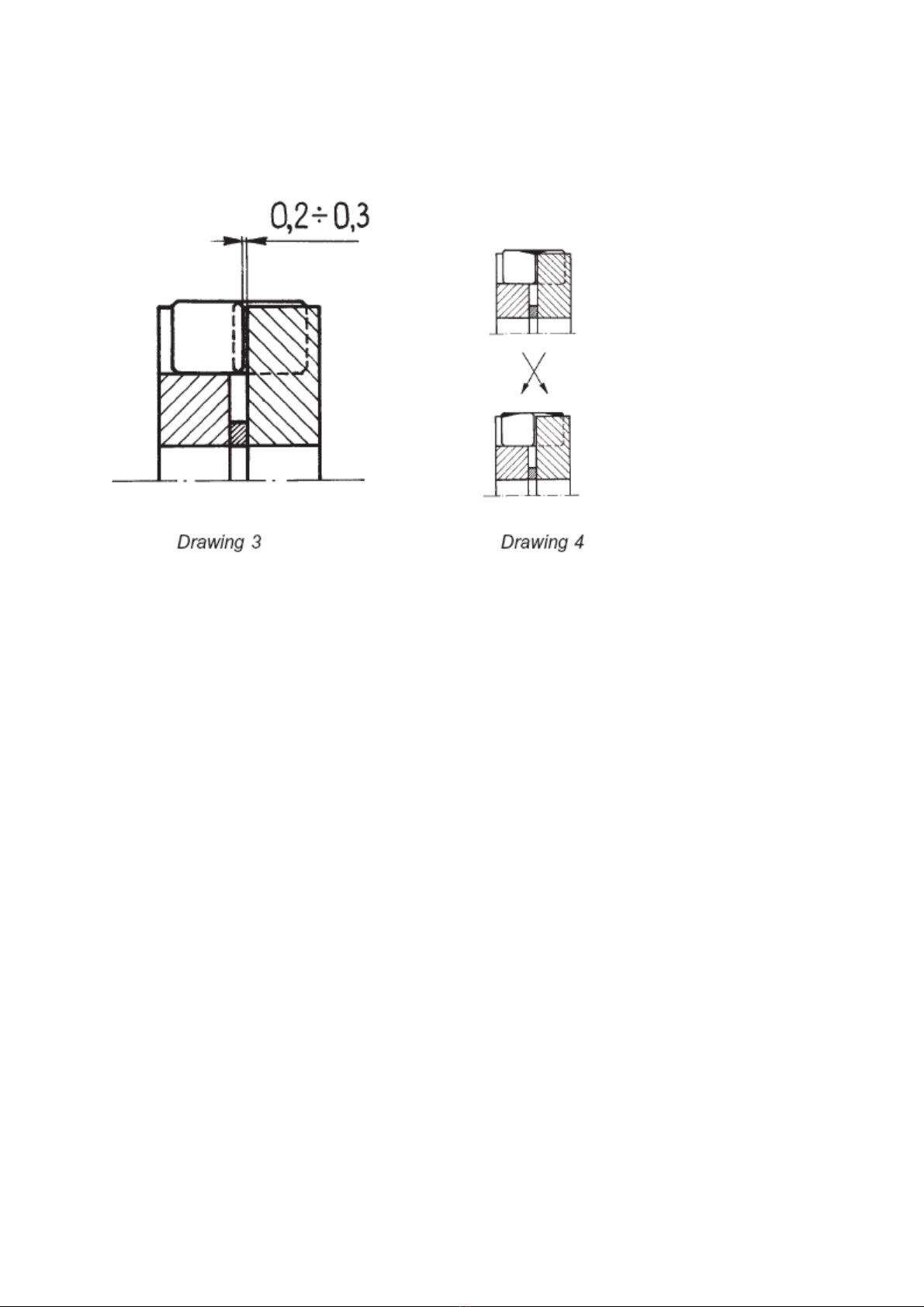
5. If the width of cut is small then swap all inserts according to drawing No4,
thus extending their life even longer.
D.nr. Art. nr. Description
1 LKF.0001 Motor Assembly
2 LKF.0041 Stop pin
3 LKF.0006 Holder set
4 LKF.0011 Cushion Washer
5 LKF.0016 Bolt
6 LKF.0021 Nut
7 LKF.0026 Feed Bolt
9 LKF.0036 Spindle Housing
10 LKF.0086 Slides mounting II
11 LKF.0076 Slides mounting I
12 LKF.0057 Bolt
13 LKF.0066 Spring washer
14 LKF.0071 Washer
15 LKF.0061 Guide Slide I
16 LKF.0056 Bolt
17 LKF.0081 Guide Slide II
18 LKF.0056 Bolt
19 LKF.0060 Roller
LKF.0500 Rolling Guide (#17 + 2x#19)
20 LKF.0071 Washer
21 LKF.0046 Spring washer
22 LKF.0051 Lock Handle
LKF.0051/2 Lock Handle

23 LKF.0126 Milling Head Arbor
24 LKF.0131 Motor key
25 LKF.0136 Milling Head (1pc.)
26 LKF.0141 Milling Head key
27 LKF.0146 Distance ring
28 LKF.0151 Insert Bolt
29 LKS.10 Cutting Plate Gold
LKS.10R Cutting Plate Black (straight edge)
LKS.10T Cutting Plate TiAlN coated
30 LKF.0313 Washer
31 LKF.0301 Safety Washer
32 LKF.0306 Bearing Nut
33 LKF.0011 Cushion Washer
34 LKF.0311 Bolt
35 LKF.0381 Controller Cover
36 LKF.0351 Seal
37 LKF.0396 Internal Insulation
38 LKF.0356 Capacitor
39 LKF.0361 Rubber ring
40 LKF.0389 Nut
41 LKF.0386 Spring washer
42 LKF.0376 Washer
43 LKF.0366 Screw
44 LKF.0391 Seal L120
45 020.0031 Coupling nut
46 LKF.0400 Plastic Nut
47 020.0036 Main Cable
48 LKF.0326 Seal L520
49 LKF.0346 Cover
50 LKF.0316 Controller unit
51 LKF.0331 Red indicator
52 LKF.0341 Amber indicator
53 020.0011 Main Switch (magnet switch)
54 020.0006 On/Off Switch
55 LKF.0401 Cover insulation
56 LKF.0402 Nut for On/Off Switch
57 020.0016 Fuse holder
58 020.0017 Fuse F2A
59 LKF.0336 Screw
not on drawing LKF.0406 Tool Box
not on drawing LKF.0411 Tool for bearing nut
not on drawing LKF.0416 Pusher tool
not on drawing LKF.0421 Puller tool
not on drawing CAS.200/3 Metal case for LKF.200


Table of contents
Other Euroboor Power Tools manuals


Popular Power Tools manuals by other brands


Makita
Makita RP1110 instruction manual

Blue Pneumatic
Blue Pneumatic BP-50 operating instructions

SUHNER MACHINING
SUHNER MACHINING SPINDLEmaster BEX 8 Technical document

Tutco SureHeat
Tutco SureHeat F068462 operating manual

Hitachi
Hitachi N 5010A Instruction and safety manual

Big Daishowa
Big Daishowa BBT40-AG90-CA4SGM-226 Operation manual


