Tutco SureHeat F068462 User manual

J800-258-8290 / 603-418-7648 K: 603-772-1072
Website: www.tutcosureheat.com E-mail: support@tutcosureheat.com
Hot Air Tool Air Heaters
FOR SAFETY & LONG HEATER LIFE, CAREFULLY READ THIS MANUAL BEFORE USE.
Safety
SHOCK HAZARD!
Only qualified individuals should install this heater and related controls.
Follow all applicable electrical codes and use proper wiring.
BURN/FIRE/EXPLOSION HAZARD!
Do not use in hazardous environments, and/or near explosive or reactive gases, or
combustible materials. Avoid contact with the heater or exit accessories during or soon
after operation. DO NOT USE NEAR VOLATILE OR COMBUSTIBLE MATERIALS.

2
Description
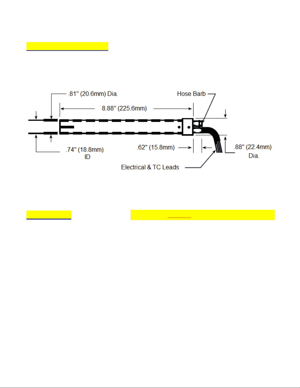
Compact, efficient heater with stainless steel housing and positive hose-barb air connection for heating air or inert
gases to 1400°F (760°C). Built in “K” Thermocouple allows for closed-loop control of temperature to ±1°F of set
point. If operated correctly, the heater will operate continuously for 5000 hours or longer.
Limited Warranty
Tutco SureHeat warrants that all products to be delivered hereunder will be free from defects in material and
workmanship at the time of delivery. Tutco SureHeat’s obligation under this warranty shall be limited to (at its
option) repairing, replacing, or granting a credit at the prices invoiced at the time of shipment for any of said
products. This warranty shall not apply to any such products which shall have been repaired or altered, except
by Tutco SureHeat, or which shall have been subjected. Tutco SureHeat shall be liable under this warranty
only if (A) Tutco SureHeat receives notice of the alleged defect within sixty (60) days after the date of
shipment; (B) the adjustment procedure hereinafter provided is followed, and (C) such products are, to Tutco
SureHeat’s satisfaction, determined to be defective.
THE WARRANTY SET FORTH IN THE PRECEDING PARAGRAPH IS EXCLUSIVE AND IN LIEU OF ALL
OTHER WARRANTIES, EXPRESS OR IMPLIED, INCLUDING, WITHOUT LIMITATION, ANY IMPLIED
WARRANTY OF FITNESS FOR A PARTICULAR PURPOSE OR OF MERCHANTABILITY.
The information contained in this manual is based on data considered to be true and accurate.
Reasonable precautions for accuracy has been taken in the preparation of this manual, however Tutco
SureHeat assumes no responsibility for any omissions or errors, nor assumes any liability for damages that
may result from the use of the product in accordance with the information contained in this manual.
Please direct all warranty/repair requests or inquiries to the place of purchase, and provide the following
information, in writing:
(A) Order number under which products were shipped
(B) Model/Serial Number of product
(C) Reason for rejection
PRODUCTS CAN NOT BE RETURNED TO TUTCO SUREHEAT WITHOUT AUTHORIZATION.
Replacement, repair, or credit for products found to be defective will be made by the place of purchase. All
products found to be not defective will be returned to the Buyer; transportation charges collect or stored at Buyer’s
expense.

3
Heater Models and Parts List
Part
Number Maximum
Wattage Maximum
Volts Maximum
Amperage Minimum Flow
SCFH (SLPM)
F068462 1500 120 13
60 (28)
F068463 2000 240 9
F068464 3500 240 15
F070878 2000 240 9
F071383 3500 240 9
F075145 3500 240 15
Specifications
Maximum Inlet Pressure 60 PSI (4 BAR)
Minimum Inlet Pressure 0.3 PSI (20mBAR)
Maximum Inlet Air Temperature 120°F (50°C)
Maximum Exit Air Temperature 1400°F (760°C) (see page 6 for Performance Curves)
Minimum Airflow 60 SCFH (28 SLPM)
UL File # E177292 (only for those Part #s listed above; otherwise contact factory)
General Information
Environmental Conditions:
Ambient Temperature 32°F to 104°F (0°C to 40°C)
Humidity 0% to 95% R.H.
Ventilation:
Use in a well-ventilated area away from excess dust, dirt, and moisture.
Cleaning:
With unit OFF and unplugged, exterior surfaces may be wiped clean using a dry, lint-free cloth.
Protective Earthing:
Each heater comes with a convenient grounding stud and hardware located at the inlet of the heater for
protective means of earthing.

4
Dimensions/Mounting
NOTE:The inlet side of the heater is located where the electrical leads and thermocouple wires come out of the
housing. Failure to install the heater in its proper orientation can result in heater damage and is not covered
under the manufacturer’s warranty.
Precautions
1. Use filtered air. Avoid grease, oil, or oil vapors, corrosive or reactive gases which will damage heater.
Note: When using compressed air a pressure reduction valve and an oil & water separation unit should be
installed to avoid contaminating the heater and reduce heater life.
2. Operate at safe voltages as shown on the Performance Curves (see page 6). Excess voltage will cause
premature failure.
3. Always have sufficient airflow through the heater before applying power. Otherwise element will overheat
very quickly, and burn out. NOTE: A thermocouple cannot detect temperatures if there is no flow – turn on
flow before applying power, even when a controller with a thermocouple is being used.
4. Use phase angle fired power controllers. On-Off controllers may shorten heater life (or burnout element).
5. For closed-loop control, use exposed junction type “K” thermocouple located within one inch of the heater
exit.
6. For closed-loop control, use a temperature controller with a fast sampling period (<500ms) and minimal
overshoot.
CAUTIO
N
:
DO NO
T
Operate Heater Without Ai
r

5
Installation
Securely mount the heater before wiring.
WARNING: THE INLET AIR/GAS SIDE OF THE HEATER IS LOCATED CLOSEST TO WHERE THE
POWER LEAD CONNECTIONS ARE MADE. INSTALLING THE HEATER IN THE WRONG ORIENTATION
WILL DAMAGE THE HEATER AND CAN CREATE ADDITIONAL HAZARDS AS A RESULT.
1. Securely mount the heater. Do not clamp so tightly as to distort the stainless steel housing.
2. Connect the filtered air source to the heater using ¼” ID high pressure tubing.
3. Connect the two power leads, grounding screw, and thermocouple leads to the appropriate connections. For
“K” thermocouples, the red lead is negative (-), and the yellow lead is positive (+).
4. If a thermocouple is used external to the heater, ensure that it is located within one inch from the heater exit.
Typical Wiring for Hot Air Tools with Closed Loop Control

6
Operation (with Heater)
START-UP
1. Reference the Performance Curves section (see page 6) for operational parameters before attempting to
operate heater(s).
2. Turn on air and set pressure or flow to desired operating level.
3. If using a closed loop system, turn on power to the temperature and power controller, then set the desired
temperature on the temperature controller. If using an open loop system, increase power to the heater
through the power controller until the desired temperature is attained.
SHUT-DOWN
1. Turn off Main Power circuit breaker, or disconnect MAIN POWER line.
2. Allow air to continue to flow for a minimum of 1 minute or until exit air temperature is 300°F (150°C) or less
for safety. Continue airflow longer as necessary to prevent burn hazard to personnel.
3. Turn off air to the system.
Performance Curves
The attached performance curves show exit air temperatures at different airflows and voltages. Pressure
readings (longer dashed lines) are measured at the inlet to the heater with no entrance or exit restrictions. Solid
lines indicate safe, normal-life operating conditions. The shorter dash lines indicate marginal, shorter-life
operating conditions leading to premature burnout. With a known flow (or pressure) at the heater entrance, follow
the flow (or pressure) line across until it meets the desired temperature curve. Drop a line straight down to
intersect the x-axis. This point, along the “Heater volts – true RMS” axis, represents the voltage required to
generate the desired exit air temperature at the chosen flow rate (inlet pressure).

7

8
Troubleshooting and Replacing Heaters
1. Note that “TYPICAL” Element Life is APPROXIMATELY 5000 hours. This is based on heater element
operating at or below temperatures shown on PERFORMANCE CURVE. In addition to normal end of life,
elements can fail due to mechanical damage, or problems with the control system.
2. If an element has failed prematurely, it should be inspected to determine the cause of the element failure.
3. When replacing or troubleshooting heaters, turn off power to the system and be sure to follow lock-out/tag-
out procedures.
a. For Troubleshooting Heater
i.) Use multi-meter to check continuity between:
1. Power terminals H1 to H2
2. Thermocouples positive (+ yellow) to negative (- red)
ii.) If there is continuity on all above tests, check system wiring:
1. Crossed thermocouple wires.
2. Reversed thermocouple wire polarity – note RED is NEGATIVE.
3. Verify inlet air temp is below set point on INLET TEMP controller.
iii.) If there is no continuity on any test, then contact technical support for assistance.
4. Remove entire heater assembly from system. Internal components are typically not replaceable.
5. Reconnect thermocouples, power and ground wires for new/replacement heater.
6. Attach any covers and operate heater as normal.

9
Element Life & Proper Control Setup
(This is published by the element wire manufacturer. It is considered typically and not a guarantee on heater life)
The typical life of an Tutco SureHeat Hot Air Tool is directly based on the temperature of the filament wire.
The curve below shows that 5000 hours of life can be obtained by maintaining a filament temperature below
1900°F. Also note that the element does not fail until it reaches more than 2200°F!
•Tutco SureHeat process air heaters contain high watt-density elements and must be
controlled carefully to prevent element failure.
•Sudden applications of power can damage heater and void warranty.
•Following each of these guidelines will help to ensure safe heater operation.
Start the heater with a 0º(F or C)Set-Point (SV): This will ensure the output signal to the power control
starts off low (0% output) before the contactor is engaged and immediately applying full power.
Use proper closed loop control (PID) settings. Tutco SureHeat typically uses the following PID;
Proportional (P), Integral (I) and Derivative (D); settings as a starting point for stable temperature control.
Some manual tuning may be required for more precise control.
Description: Range: Default:
(P) roportional 90-250 131
(I) ntegral 8-20 9
(D) erivative 0-2 2
Scan/Cycle Rate < 500mSec 200mSec
Incorporate a Ramp Rate for the start-up of the heater. The slower you ramp to your final set-point the
less overshoot and problems you will have. Tutco SureHeat process heaters should be ramped up to
temperature over a period of several minutes. The following are recommended ramp rates based on final
temperature. (For custom ramp rates consult with factory)
Set-Point Temperature Degrees per Minute
Up to 600ºF (up to 300ºC) 360ºF (150ºC)
601-1000ºF (301-500ºC) 240ºF (100ºC)
1001-1400ºF (501-760ºC) 120ºF (50ºC)
Up to1650ºF (up to 900°C) 60ºF (25ºC)

Tutco SureHeat •22 Industrial Drive •Exeter, NH 03833 USA
J800-258-8290 / 603-418-7648 K: 603-772-1072
Website: www.tutcosureheat.com E-mail: support@tutcosureheat.com
The technical data and specifications supplied in this operating manual are subject
to change without prior notice. Contact Tutco SureHeat for additional assistance.
This manual suits for next models
5
Table of contents