Eurolube 16721 User manual

www.eurolube.com 205203 EUROLUBE EQUIPMENT AB
PART NO 16721, 16724, 16813, 16868 / ART.NR. 16721, 16724, 16813, 16868
HIGH VOLUME OIL CONTROL GUN
SERVICE GUIDE
2020-02 ORIGINAL MANUAL
1
General
High volume hose end control gun with ergonomic and
progressive grip for better control of dispensing and
In-line meter both with digital volume meter for oil and
glycol (certain models). Maximum working pressure 100
bar. Please refer to the sales Catalogue for details on
accessories. Or visit our website: www.eurolube.com
WARNING! Do NOT use solvents or other explosive
fluids. Never point a control valve at any portion of
your body or another person. Accidential discharge
of pressure and/or material can result in injury. Read
these instruction carefully before installation, operation
or service.
DO NOT EXCEED MAXIUMUM PRES-
SURE
Allmänt
Handmätare för höga öden med ergonomiskt handtag
och progressiv ventil för optimal ödeskontroll. Digital
volymmätare för olja och glykol (vissa modeller). Maxi-
malt arbetstryck 100 bar. För detaljerad information,
hänvisar vi till vår kompletta produktkatalog, eller vår
hemsida: www. eurolube.com
VARNING! Ventilerna får EJ användas för tappning av
bensin eller andra (explosiva) kemikalier. Rikta aldrig
utloppsmunstycke mot någon kroppsdel eller någon
annan person. Vätska kan lätt tränga in igenom hud och
förorsaka skador. Läs dessa intruktioner innan installa-
tion, användning eller vid service.
ÖVERSKRID EJ MAX ARBETSTRYCK
PART NO / ART.NR 16721, 16724, 16813, 16868
Maximum ow (with extension) / max öde (inkl. utloppsrör) 80 l/min
Pressure drop at max ow / tryckfall vid max öde 3 bar (44 psi)
Max working pressure / max arbetstryck 100 bar (1450 psi)
Temperature operating range / temperaturarbetsområde -10°C – +70°C
Burst pressure / sprängtryck 400 bar (5800 psi) minimum
Fluid inlet / anslutning 3/4” BSP (F/Inv.)
Fluid compatibility / vätskekompabilitet Engine oil, hydraulic oil, antifreeze uid /
motorolja, hydraulolja, glykol
Vikt / weight 2,05 kg (4,52 lbs)
TECHNICAL DATA / TEKNISKA DATA
MEASUREMENTS / MÅTT
130 mm
580 mm
130 mm
506 mm
30°
16721
16724
www.eurolube.com
EUROLUBE EQUIPMENT 205203
PART NO 16721, 16724, 16813, 16868 / ART.NR. 16721, 16724, 16813, 16868
HIGH VOLUME OIL CONTROL GUN
2
General
The control valve has been designed to dispense a variety of uids. These include
engine oils, hydraulic oils and antifreeze uid.
The balanced control valve allows a progressive opening for better control of uid
delivery. The valve can be locked in open position by means of the trigger button.
The control valve includes a trigger guard to prevent accidental opening.
Safety precautions
1. Only use the unit for the purposes for which is intended.
2. Do not alter or modify the unit.
3. Do not exceed the maximum working pressure or temperature. See page of
technical specications.
4. Do not point dispense valve at anyone or at any part of the body. Use the
equipment with uids which are compatible with the moist parts of the equipment.
See the relevant section of technical specications.
5. Observe the manufacturer´s safety warnings for the uids used.
Dispensing
To dispense uid, proceed as follows:
1. Pull the trigger to begin dispensing.
2. Release the trigger to stop dispensing.
3. After use, the nozzle should be closed to prevent leakage onto oors etc.
Locking the trigger
To lock the trigger in dispensing position, proceed as follows:
1. Pull the trigger to its maximum opening (g. 1).
2. Push the lock button (g. 2).
3. Release the trigger holding the button down until it locks (g. 3).
4. Once the desired quantity is dispensed, pull the trigger to its maximum position to
release the lock.
Allmänt
Oljeventilen har utformats för att tappa en mängd olika vätskor. Dessa inkluderar
motoroljor, hydrauloljor och glykol.
Den balanserade ventilen tillåter en progressiv öppning för bättre kontroll av
vätskeleveransen. Ventilen kan låsas i öppet läge med hjälp av en spärr.
Ventilen är utrustad med ett skydd för avtryckaren för att förhindra oavsiktlig öppning.
Säkerhetsanvisningar
1. Använd bara enheten för de ändamål för vilka den är avsedd.
2. Ändra inte eller bygg ej om enheten.
3. Överskrid inte maximalt arbetstryck eller temperatur. Se tekniska specikationer.
4. Rikta inte ventilen mot någon eller mot någon del av kroppen. Använd utrustningen
med vätskor som är kompatibla med våtdelarna i utrustningen. Se relevanta avsnitt
av tekniska specikationer.
5. Beakta vätskeleverantörens säkerhetsvarningar för de vätskor som hanteras.
Tappning av vätska
Gör så här för att tappa vätska:
1. Tryck in avtryckaren för att börja tappningen.
2. Släpp avtryckaren för att stoppa tappningen.
3. Efter användning bör non-drip munstycket stängas för att undvika läckage på golv
och dylikt.
Låsning av avtryckaren
För att låsa avtryckaren:
1. Håll in avtryckaren så mycket det går (g 1).
2. Tryck in låsknappen (g 2).
3. Släpp avtryckaren tills spärren går i (g 3).
4. När önskad volym uppnås, håll in avtryckaren helt för att lossa på spärren.
General
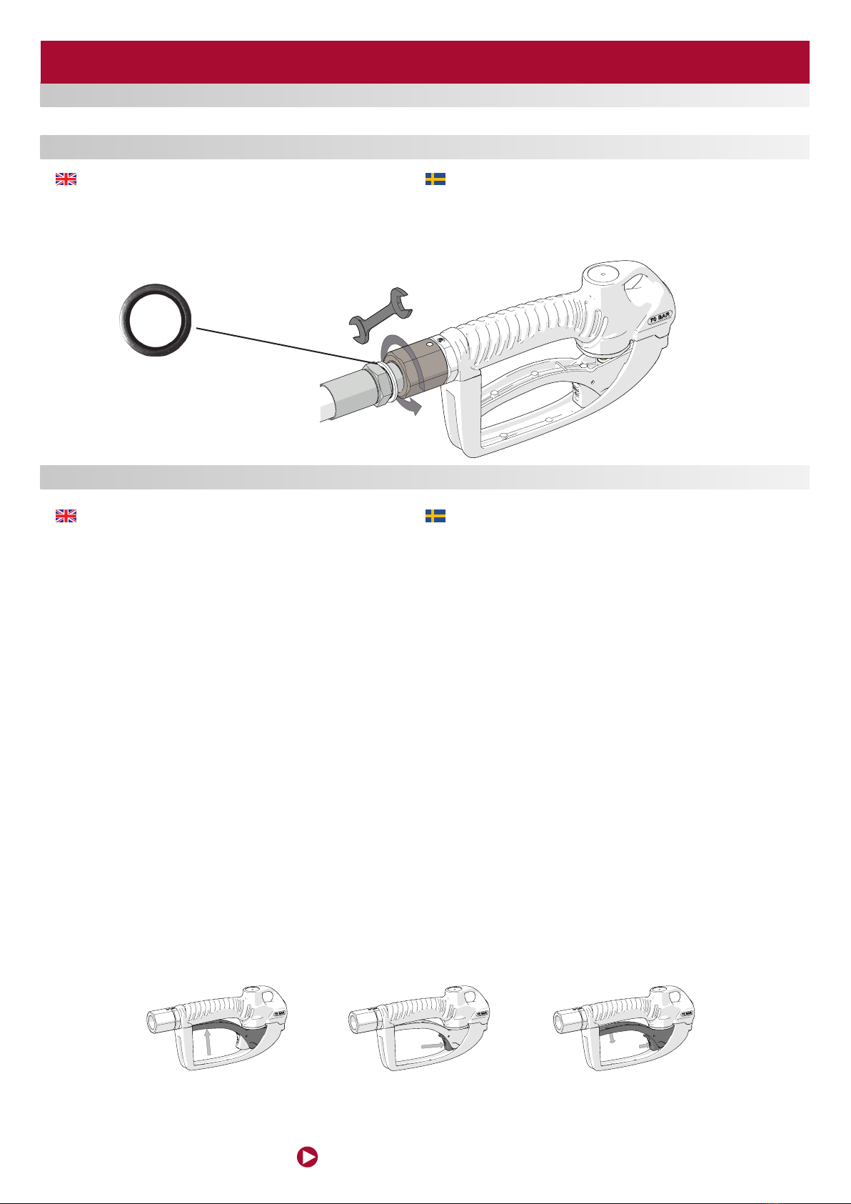
The connection of the extension to the control valve outlet is performed by a 3/4”
bonded seal. Check the tightness to prevent leakage.
To connect the control valve to the uid line, keep xed the control valve body and the
end of the hose while rotate the free end of the swivel until achieves the desired torque.
Sealing should be achieved by means of 3/4” bonded seal (part no 1367422)
Allmänt
Anslutning av utloppsröret sker med hjälp av en 3/4” gummistålbricka. Kontrollera dess
täthet för att undvika läckage.
För att enklast ansluta oljeventilen till vätskeledningen, xera oljeventilens hus och
slangen, och gänga på sviveln på slangen och dra åt tills det blir tätt.
Anslutningen bör tätas med en 3/4” gummistålbricka (art nr 1367422)
INSTALLATION / INSTALLATION
OPERATION / ANVÄNDNING
1367422
FIG 1 FIG 2 FIG 3
www.eurolube.com 205203 EUROLUBE EQUIPMENT
PART NO 16721, 16724, 16813, 16868 / ART.NR. 16721, 16724, 16813, 16868
HIGH VOLUME OIL CONTROL GUN
3
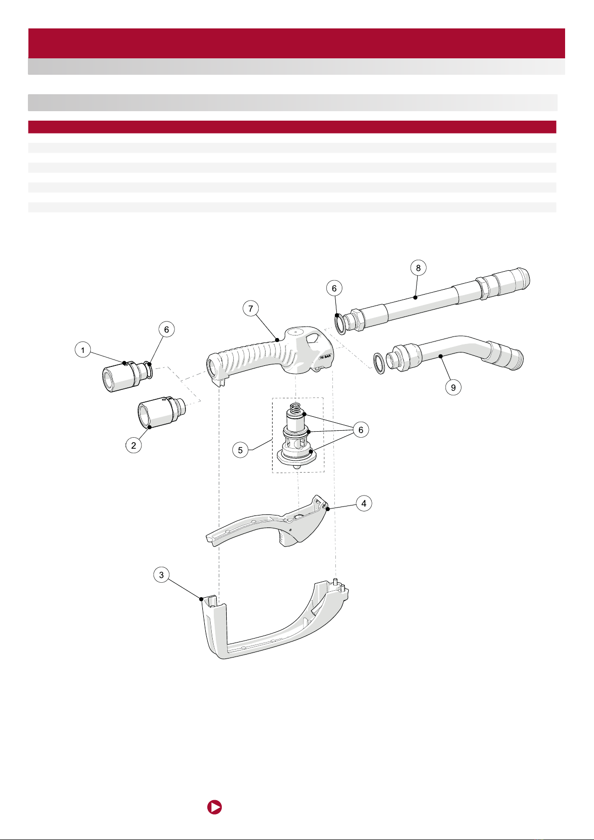
ITEM / POS NAME / BENÄMNING PART NO / ART.NR.
1 Swivel 3/4” / svivel 3/4” 1060101
2 Swivel 1” / svivel 1” 16711
3 Trigger guard / avtryckarskydd 1060102
4 Trigger / avtryckare 1060103
5 Valve / ventil 1060104
6Seal kit / tätningssats 1060105
7Valve body / ventilhus 1060106
8Outlet hose / utloppsslang 1060107
9Outlet tube / utloppsrör 1168690
EXPLODED VIEW / SPRÄNGSKISS
www.eurolube.com
EUROLUBE EQUIPMENT 205203
PART NO 16721, 16724, 16813, 16868 / ART.NR. 16721, 16724, 16813, 16868
HIGH VOLUME OIL CONTROL GUN
4
DEUTSCH
ESPAÑOL ENGLISHSVENSKAFRANÇAIS
Pos. Réf Désignation Qte.
1Vis de carter 8
Couvercle de chambre de mesure 1
2
Joint torique 1
Engrenages ovales 2
Aimant 2
3 2040700
Carte électronique 1
Carter 1
Vis avec pas en plastique PCB 4
Vis de carter en plastique 4
4Carter 1
Vis autotaraudeuse 4
105088
Alentec & Orion AB Grustagsvägen 4, SE-13840, Älta, SWEDEN · info@alentec.se · www.alentec.com
3
PIÈCES DE RECHANGE POUR 25050, 25055, 25052, 25051
8836 889 R. 12/18
GARTEC SRL · Castronno (VA) · Via Olona 4/A · Phone: +39 0332 895026 · Fax: +39 0332 895061 · Email: [email protected]
EN
2018_12_14-12:00
Pos. Part No. Description Qty.
1 369636 Countersunk screw 8
Measuring chamber lid 1
2 369633
O-ring 1
Oval gear 2
Magnet 2
3 369635.700
Electronic card 1
Casing 1
Screw with plastic thread PCB 4
Screw with plastic thread casing 4
SPARE PARTS
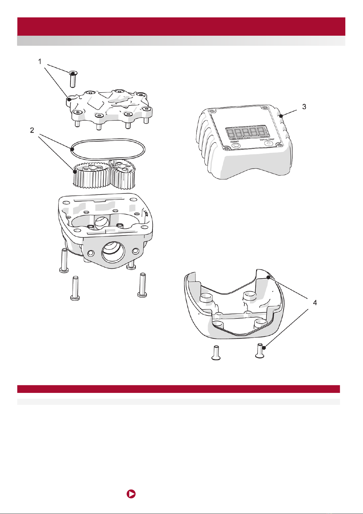
ITEM / POS NAME / BENÄMNING PART NO / ART.NR.
1 Meter chamber cover including 8 screws / täcklock inkl skruvar 8st 1064001
2 Oval gears and O-rings / ovala kugghjul inkl o-ring 1064002
3Cover and circuit board / kåpa med kretskort 1060070

www.eurolube.com 205203 EUROLUBE EQUIPMENT
PART NO 16721, 16724, 16813, 16868 / ART.NR. 16721, 16724, 16813, 16868
HIGH VOLUME OIL CONTROL GUN
5
The calibration process is semi-automatic. To start the process, the meter must be in
partial meter mode (g. 14) and is accessed by simultaneously pressing the buttons
RESET and TOTAL/TRIP for 3 seconds (g. 15). After releasing the buttons the current
calibration factor is shown on the meter (g. 16).
If the screen does not show the correct measuring unit (g. 16) press the TOTAL/TRIP
button (g. 17) successively until displaying the required unit (g. 18). Press RESET (g.
19) to start the calibration process (g. 20).
It now starts to release the desired volume into the container. Remember that you
must release at least 2 litres to perform a good calibration. In the example shown in
the gures it is assumed that 2 litres are released according to the reading on the
calibrated container and that the meter records 2.1 litres (g. 21).
To administer the real quantity released (which is that measured in the calibrated
container or scales), press the RESET button for 1 second (g. 22). The digits start to
ash (g. 23) indicating that the value shown can be modied. Each press of the RESET
button increases the value by 0.1 litres and each press of the TOTAL/ TRIP button (g.
24) reduces this value by 0.1 litres (g. 25).
Once the real value released is set (g. 25) press the RESET button for 1 second (g.
26). The meter shows the new stored calibration factor (g. 27) and then exits the
calibration process. The screen shows the partial meter with the units set during the
calibration process (g. 28). If, during any phase of the calibration process, you wish
to exit without saving the changes made you must press the TOTAL/TRIP button for
1 second. Likewise, if 30 seconds of inactivity elapse during the process, the meter
switches off automatically and exits the calibration process without storing the data.
Kalibreringsproceduren är halvautomatisk. För att starta kalibreringen måste mätaren
stå i normal läge (g. 14). Tryck och håll in TOTAL/TRIP samt RESET knappen i tre
sekunder. När knapparna släpps kommer kalibreringsfaktorn visas i fönstret (g. 16).
Om fel enhet visas i fönstret (g. 16) tryck på TOTAL/TRIP tills önskad enhet visas. Tryck
på RESET (g. 19) för att starta kalibreringsprocessen (g 20).
Fortsätt genom att tappa upp minst två liter i mätcylindern. I följande exempel antas att 2
liter är tappat enligt mätcylindern och att mätaren har registrerat 2,1 liter (g. 21).
För att mata in det faktiska värde som är uppmätt i mätcylindern (eller våg)Tryck och
håll in RESET i en sekund. Siffrorna i displayen kommer att börja blinka för att visa att
de går att ändra. Varje intryckning av RESET kommer att öka värdet med 0,1 liter, varje
tryck på TOTAL/TRIP kommer minska värdet med 0,1 liter.
När det önskade värdet visas i fönstret (i detta fall 2,00), tryck och håll in RESET i en
sekund (g 26). Mätaren kommer nu att visa den nya kalibreringsfaktorn, och sedan
återgå till normalläge. Vill man i något steg avbryta kalibreringsproceduren utan att
spara några ändringar, görs detta genom att hålla in TOTAL/TRIP knappen i en sekund.
Om trettio sekunders inaktivitet inträffar kommer mätaren stängas av och återgå till
normalläge utan att spara ändringar.
CALIBRATION / KALIBRERING
105088
Alentec & Orion AB Grustagsvägen 4, SE-13840, Älta, SWEDEN · info@alentec.se · www.alentec.com
5
ENGLISHSVENSKAFRANÇAISDEUTSCH
ESPAÑOL
To administer the real quantity released (which is that measured in
the calibrated container or scales), press the RESET button for 1
second (fig. 22). The digits start to flash (fig. 23) indicating that the
value shown can be modified. Each press of the RESET button
increases the value by 0.1 litres and each press of the TOTAL/
TRIP button (fig. 24) reduces this value by 0.1 litres (fig. 25).
After the calibration process you will obtain precision within the
range of ±0.5% with the meter. If the meter exceeds this range it
could be due to the following:
• Unsuitable container used for the calibration.
The calibration process is semi-automatic. To start the process, the
meter must be in partial meter mode (fig. 14) and is accessed by
simultaneously pressing the buttons RESET and TOTAL/TRIP for
3 seconds (fig. 15). After releasing the buttons the current
calibration factor is shown on the meter (fig. 16).
If the screen does not show the correct measuring unit (fig. 16)
press the TOTAL/TRIP button (fig. 17) successively until displaying
the required unit (fig. 18).
Press RESET (fig. 19) to start the calibration process (fig. 20).
It now starts to release the desired volume into the container.
Remember that you must release at least 1 litre to perform a good
calibration. In the example shown in the figures it is assumed that
2 litres are released according to the reading on the calibrated
container and that the meter records 2.1 litres (fig. 21).
• The container is not empty before the calibration.
• Air in the fluid which has not been completely removed.
• The values are not properly introduced into the calibration
process.
Once the real value released is set (fig. 25) press the RESET
button for 1 second (fig. 26). The meter shows the new stored
calibration factor (fig. 27) and then exits the calibration process.
The screen shows the partial meter with the units set during the
calibration process (fig. 28).
If, during any phase of the calibration process, you wish to exit
without saving the changes made you must press the TOTAL/TRIP
button for 1 second. Likewise, if 30 seconds of inactivity elapse
during the process, the meter switches off automatically and exits
the calibration process without storing the data.
CALIBRATION
CALIBRATION CAPACITY
CALIBRATION PROCEDURES
Fig. 14 Fig. 15 Fig. 16
Fig. 21
Fig. 17 Fig. 19Fig. 18 Fig. 20
Fig. 22 Fig. 23 Fig. 24 Fig. 25
3"
1"
1"
Fig. 26 Fig. 27 Fig. 28
TOTAL / TRIP
TOTAL / TRIP
TOTAL / TRIP

EUROLUBE EQUIPMENT
Alentec & Orion AB, Grustagsvägen 4, SE-138 40 Älta, Sweden
www.eurolube.com
PART NO 16721, 16724, 16813, 16868 / ART.NR. 16721, 16724, 16813, 16868
HIGH VOLUME OIL CONTROL GUN
6
DECLARATION OF CONFORMITY / DEKLARATION OM ÖVERENSSTÄMMELSE
Benny Carlsson,
Product director (Authorized representative for
Eurolube Equipment / Alentec & Orion AB and
responsible for technical documentation).
Produktansvarig (Auktoriserad representant för
Eurolube Equipment / Alentec & Orion AB och
ansvarig för teknisk dokumentation).
Alentec & Orion AB, Grustagsvägen 4, 138 40 Älta Sweden, declares hereby that the
products:
HIGH VOLUME OIL CONTROL GUN
PART NO 16721, 16724, 16813, 16868 / ART.NR. 16721, 16724, 16813, 16868 are in confor-
mity with the requirements of the Council´s Machinery Directive 2006/42/EC.
Älta February 26, 2020
Alentec & Orion AB, Grustagsvägen 4, 138 40 Älta, deklarerar härmed att produkterna:
HIGH VOLUME OIL CONTROL GUN
PART NO 16721, 16724, 16813, 16868 / ART.NR. 16721, 16724, 16813, 16868 är tillverkade
i överensstämmelse med bestämmelserna i Maskindirektivet 2006/42/EC.
Älta Februari 26, 2020
This manual suits for next models
3
Table of contents


