Euromaid INLCP92BGRCPACK User manual

User Manual
FP
%ODFN*ODVV
:DOO&anopyZLWK5RRI&DYLW\0RWRU
INLCP92BGRCPACK
90cm Black Glass Wall Canopy with External Wall Motor
INLCP92BGEMPACK


2
Content
1…………………………………..………………………………Safet
y
instructions
2…………………………………..………………………………Installation
3…………………………………..………………………………Start using your Rangehood
4…………………………………..………………………………Troubleshooting
5…………………………………..………………………………Maintenance and cleanin
g
6…………………………………..………………………………Environment protection
SAFETY INSTRUCTIONS
This manual explains the proper installation and use of your Rangehood, please read
itcarefully before using even if you are familiar with the product. The manual should be
keptin a safe place for future reference.
These instructions shall also be available in an alternative format, e.g. on a website or
on request from the user in spec sheet format.

3
Things not to do:
ƔDo not try to use the Rangehood
without the grease filters or if the filters
are excessively greasy!
Ɣ'RQRWLQVWDOODERYHDFRRNHUZLWKD
high level grill.
Ɣ'RQRWOHDYHIU\LQJSDQVXQDWWHQGHG
during use because overheated fats or
oils might catch fire.
ƔNever leave naked flames under the
Rangehood.
Ɣ,IWKHRangehood is damaged, do not
attempt to use.
Ɣ'RQRWIODPEpXQGHUWKHRangehood.
Ɣ&$87,21$FFHVVLEOHSDUWVPD\
become hot when used with cooking
appliances.
Ɣ7KHPLQLPXPGLVWDQFHEHWZHHQWKH
supporting surface for the cooking
vessels on the hob and the lowest part
of the Rangehood. (When the
Rangehood is located above a gas
appliance, this distance shall be at
least 75 cm)
Ɣ7KHDLUPXVWQRWEHGLVFKDUJHGLQWRD
flue that is used for exhausting fumes
from appliances burning gas or other
fuels.
Things to always do:
Ɣ,PSRUWDQW$OZD\VVZLWFKRIIWKH
electricity supply at the mains during
installation and maintenance such as
light bulb replacement.
Ɣ7KHRangehood must be installed in
accordance with the installation
instructions and all measurements
followed.
Ɣ$OOLQVWDOODWLRQZRUNPXVWEHFDUULHGRXW
by a competent person or qualified
electrician.
Ɣ3OHDVHGLVSRVHRIWKHSDFNLQJPDWHULDO
FDUHIXOO\&KLOGUHQDUHYXlnerable to it.
Ɣ3D\DWWHQWLRQWRWKHVKDUSHGJHV
inside the Rangehood especially
during installation and cleaning.
Ɣ:KHQWKHRangehood is located above
a gas appliance, the minimum
distance between the supporting
surface for the cooking vessels on the
hob and the lowest part of the
Rangehood WKDWGLVWDQFHPXVWEH
*DVFRRNHUV 75 cm
(OHFWULFFRRNHUV 65 cm
&RDORURLOFRRNHUV 75 cm
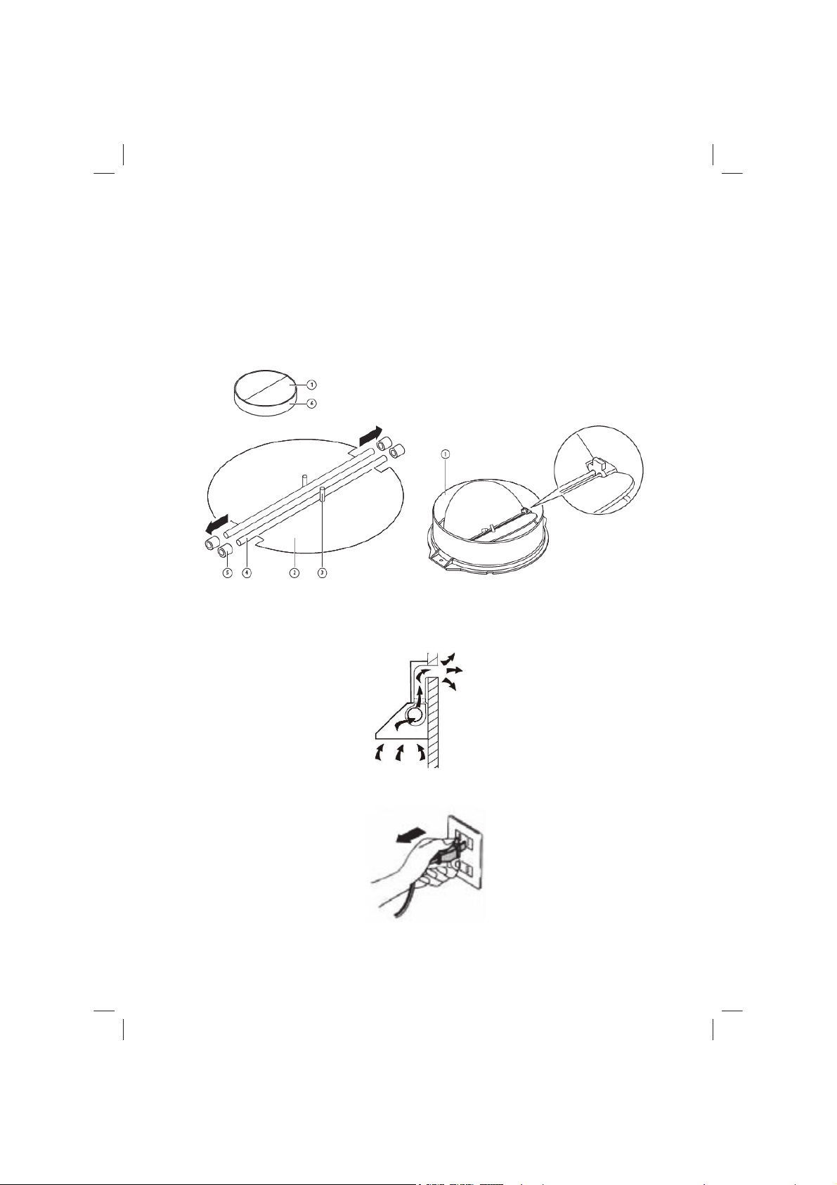
Ɣ0DNHVXUHWKHGXFWLQJKDVQREHQGV
sharper than 90 degrees as this will
reduce the efficiency of the
Rangehood.
Ɣ:DUQLQJ)DLOXUHWRLQVWDOOWKHVFUHZVRU
fixing device in accordance with these
instructions may result in electrical
hazards
Ɣ:DUQLQJ%HIRUHREWDLQLQJDFFHVVWR
terminals, all supply circuits must be
disconnected.
Things to always do:
Ɣ$OZD\VSXWOLGVRQSRWVDQGSDQVZKHQ
cooking on a gas cooker.
ƔWhen in extraction mode, air in the
room is being removed by the
Rangehood3OHDVHPDNHVXUHWKDW
proper ventilation measures are being
observed. The Rangehood removes
odours from room but not steam.

4
ƔRangehood is for domestic use only.
ƔIf the supply cord is damaged, it must
be replaced by the manufacturer, its
service agent or similarly qualified
persons in order to avoid a hazard.
ƔThis appliance is not intended for
use by persons (including children)
with reduced physical, sensory or
mental capabilities, or lack of
experience and knowledge, unless
they have been given supervision or
instruction concerning use of the
appliance by a person responsible for
their safety.
Ɣ:DUQLQJ%HIRUHREWDLQLQJDFFHVVWR
terminals, all supply circuits must be
disconnected.
Things to always do:
Ɣ&DXWLRQ7KHDSSOLDQFHDQGLWV
accessible parts can become hot
GXULQJRSHUDWLRQ%HFDUHIXOWRDYRLG
touching the heating elements.
&KLOGUHQ\RXQJHUWKDQ\HDUVROG
should stay away unless they are
under permanent supervision.
Ɣ7KHUHVKDOOEHDGHTXDWHYHntilation of
the room when the Rangehood is
used at the same time as appliances
burning gas or other fuels.
Ɣ7KHUHLVDILUHULVNLIFOHDQLQJLVQRW
carried out in accordance with the
instructions
Ɣ5HJXODWLRQVFRQFHUQLQJWKHGLVFKDUJH
of air have to be fulfilled.
Ɣ&OHDQ\RXUDSSOLDQFHSHULRGLFDOO\E\
following the method given in the
FKDSWHU0$,17(1$1&(
Ɣ)RUVDIHW\UHDVRQSOHDVHXVHRQO\WKH
same size of fixing or mounting screw
which are recommended in this
instruction manual.
Ɣ5HJDUGLQJWKHGHWDLOVDERXWWKHPHWKRG
and frequency of cleaning, please
refer to maintenance and cleaning
section in the instruction manual.
Ɣ&OHDQLQJDQGXVHUPDLQWHQDQFHVKDOO
not be made by children without
supervision.
ƔWhen the Rangehood and appliances
supplied with energy other than
electricity are simultaneously in
operation, the negative pressure in the
URRPPXVWQRWH[FHHG3D[-5
bar).
Ɣ:$51,1*'DQJHURIILUHGRQRWVWRUH
items on the cooking surfaces.
Ɣ$ steam cleaner is not to be used.
Ɣ1(9(5WU\WRH[WLQJXLVKDILUHZLWK
water, but switch off the appliance and
then cover flame e.g. with a lid or a
fire blanket.

5
IMPORTANT INFORMATION
Points to consider for installation
1. %HIRUHLQVWDOODWLRQSOHDVHHQVXUHWKHDUHDLVFOHDQWRDYRLGVXFWLRQRIWKH
remaining bits of debris and dust.
2. 3OHDVHHQVXUHWKDWWKHIDQPRWRULVILUPO\VHFXUHGWRHLWKHUDIODWVXUIDFHVXFK
DVDQ0')SDQHODIIL[HGDFURVVWKHFHLOLQJUDIWHUVRUIL[HGWRWKHFHLOLQJUDIWHUV
themselves. Ensure the fan motor is level and there is no vibration when in use.
3. The location of the fan unit shall allow access for maintenance and repair.
3HUPDQHQWIL[HGPHDQVRIDFFHVVLVUHTXLUHGZKHUHWKHIDQXQLWORFDWLRQLV
beyond the extent of normal steps or ladders.
4. $IWHULQVWDOODWLRQPDNHVXUHWKDWWKHPDLQERG\LVOHYHOWRDYRLd grease
collection at one end.
5. 3OHDVHQRWHWKHGLPHQVLRQVRIWKHIDQPRWRUIRULQVWDOODWLRQSXUSRVHV
6. The fan motor should be secured using the supplied brackets and screws.

6
INSTALLATION - ROOF CAVITY MOTOR VERSION
Schematic diagram
1. &RQQHFW WKH Rangehood main body with the external cabinet by control wire, to
achieve power on and off, and also speed switching.
2. The control wire is separated into 3 parts, the first two parts are fixed onto the main
body and external cabinet, while the middle part is extension wire.
3. The Rangehood main body and the external cabinet will exhaust the smoke to
outdoor after installing the expansion pipe.

7
MOUNTING OF THE V-FLAP
If the Rangehood GRHVQRWKDYHDQDVVHPEOHG9-flap 1, you should mount the half-
parts to its body. The LPDJHVRQO\VKRZDQH[DPSOHRIKRZWRPRXQWWKH9-flap, the
outlet may be various according to different models and configuration.
7RPRXQWWKH9-IODS\RXVKRXOG
• Mount two half-parts 2 into the body 6
• a pin 3 should be top oriented;
• the axis 4 should be inserted in the holes 5 on body;
• repeat all the operations for the 2nd half-part
INSTALLATION
If you have an outlet to the outside, your Rangehood can be connected as below
picture by means of an extraction duct (enamel, aluminium, flexible pipe or non-
flammable material with an interior diameter of 220mm)
%HIRUHLQVWDOODWLRQWXUQWKHXQLWRIIDQGXQSOXJLWIURPWKHRXWOHW

8
2. The Rangehood should be placed at a distance of 65~75cm above the cooking
surface for best effect.
3. Install the hook on a suitable place once the installation height is fixed, and keep it
in line. The fixed position of the inside chimney bracket is the place of chimney.
See pic 2.
4. 1) Equip the outlet connecting cover onto the cabinet top, and VFUHZSFVPP
screws to fix it.
2) Install the outlet seal ring and outlet, and IL[WKHPZLWKSFVPPscrews,
see pic 3. Then hang the hood on the hook. See pic 4.

9
5. )L[WKHRXWVLGHFKLPQH\EUDFNHWRQWKHRXWVLGHFKLPQH\E\SFVPPVFUHZV
and be sure that the inside chimney can be adjusted the height in it freely, put the
chimneys onto the Rangehood. See pic 5.
6. Equip the chimneys, fix the outside chimney bracket with 2 pcs 4*40mm screws, and
use 2 pcs 4*30mm screws to fix the hood body. See pic 6.
7. 8QVFUHZWKHSFV67PPscrews, and dismantle the outlet mesh cover, see
pic 7. 1RWH7KHUHLVQRQHHGWRXQVFUHZWKHVFUHZVVKRZLQJRQSLF
Install the outlet seal ring and outlet, using WKHSFV67PPVFUHZVLQVWHSWR
fix them. See pic 9.
9. Install case installation bracket, and fix with 4 pcs M4 screws, spring washers and
gaskets. See pic 10.

10
10.Screw 4 pcs 4*30mm screws to fix the external cabinet onto the ceiling. See pic 11
& 12.
11.Install the expansion pipe and fix it with cable tie. See pic 13.
12.Equip the expansion pipe to the outlet, and fix with cable tie. Lead one end of the
expansion pipe which install on the external cabinet outlet to the RXWVLGH%RWK end
of the motor extension wire should connect with the external cabinet control wire and
the control wire of the main body top. The plastic base of the control wire should be
plugged to the bottom, and make the buckle to tight status. See pic 14.

11
1RWH<RXQHHGWRORRVHn the connecting wire before repair, follow WKHVWHSVDVEHORZ
a. Rotate the lock catch of the connecting wire following the arrow direction.
b. 3XOORXWWKHFRQQHFWRU
13.$GMXVWWKHKHLJKWRIWKHLQVLGHFKLPQH\WRWKHSRVLWLRQRIWKHLQVLGHFKLPQH\EUDFNHW
DQGIL[RQLWE\SFV67PPscrews. See pic 15.
14.Installation is finished. See 3LF
HINTS FOR EXHAUST DUCT INSTALLATION
The following rules must be VWULFWO\IROORZHGWRREWDLQRSWLPDODLUH[WUDFWLRQ
• Keep expansion pipe short and straight.
• Do not reduce the size or restrict expansion pipe.
• When using expansion pipe always install the pipe pulled taut to minimize pressure
loss.
)DLOXUHWRREVHUve these basic instructions will reduce the performance and increase
noise levels of the Rangehood.
$Q\LQVWDOODWLRQZRUNPXVWEHFDUULHGRXWE\DTXDOLILHGHOHFWULFLDQRUFRPSHWHQW
person.

12
INSTALLATION - EXTERNAL WALL HUNG MOTOR VERSION
Schematic diagram
1. &RQQHFWWKH5DQJHKRRGPDLQERG\ZLWKWKHH[WHUQDOFDELQHWE\FRQWUROZLUHWR
achieve power on and off, and also speed switching.
2. The control wire is separated into 3 parts, the first two parts are fixed onto the main
body and external cabinet, while the middle part is extension wire.
3. The Rangehood main body and the external cabinet will exhaust the smoke to
outdoor after installing the expansion pipe.

13
MOUNTING OF THE V-FLAP
If the Rangehood does not have an DVVHPEOHG9-flap 1, you should mount the half-
SDUWVWRLWVERG\7KHLPDJHVRQO\VKRZDQH[DPSOHRIKRZWRPRXQWWKH9-flap, the
outlet may be various according to different models and configuration.
7RPRXQWWKH9-IODS\RXVKRXOG
• Mount two half-parts 2 into the body 6
• a pin 3 should be top oriented;
• the axis 4 should be inserted in the holes 5 on body;
• repeat all the operations for the 2nd half-part
INSTALLATION
If you have an outlet to the outside, your Rangehood can be connected as below
picture by means of an extraction duct (enamel, aluminium, flexible pipe or non-
flammable material with an interior diameter of 220mm)
%HIRUHLQVWDOODWLRQWXUQWKHXQLWRIIDQGXQSOXJLWIURPWKHRXWOHW

14
2. The Rangehood should be placed at a distance of 65~75cm above the cooking
surface for best effect.
3. Install the hook on a suitable place once the installation height is fixed, and keep it
in line. The fixed position of the inside chimney bracket is the place of chimney. See
pic 2.
4.1) Equip the outlet connecting cover onto the cabinet top, and screw SFVPP
screws to fix it.
,QVWDOOWKHRXWOHWVHDOULQJDQGRXWOHWDQGIL[WKHPZLWKSFVPPVFUHZV
see pic 3. Then hang the hood on the hook. See pic 4.

15
5. )L[WKHRXWVLGHFKLPQH\EUDFNHWRQWKHRXWVLGHFKLPQH\E\SFVPPVFUHZV
and be sure that the inside chimney can be adjusted the height in it freely, put the
chimneys onto the Rangehood. See pic 5.
6. Equip the chimneys, fix the outside chimney bracket with 2 pcs 4*40mm screws,
and use 2 pcs 4*30mm screws to fix the hood body. See pic 6.
7. Install the wall mounted bracket, and fix with 4 pcs M4 screws, spring washers and
gaskets. See pic 7.
Equip the expansion pipe, and use stainless steel hoRSWRIL[LW6HHSLF
9. 0DNHDijPPKROHRQWKHZDOODQGOHWWKHH[SDQVLRQSLSHDQGPRWRUFRQQHFWLQJ
wire to across the wall together. Screw 4 pcs wall plugs into the wall, and then fix the
cabinet on the wall with 4 pcs 4*30mm screws. See pic 9.

16
10. Install the expansion pipe onto the main body outlet and fix it with cable tie.
&RQQHFWWKHPRWRUH[WHQVLRQZLUHERWKHQGZLWKWKHH[WHUQDOFDELQHWFRQWUROZLUHDQG
main body top control wire. The plastic base of the control wire should be plugged to
the bottom, and make the bucket to tight status. See pic 10.
1RWH<RXQHHGWRORRVHQWKHFRQQHFWLQJZLUHEHIRUHUHSDLUIROORZWKHVWHSVDVEHORZ
c. Rotate the lock catch of the connecting wire following the arrow direction.
d. 3XOORXWWKHFRQQHFWRU
g

17
11. $GMXVWWKHKHLJKWRIWKHLQVLGHFKLPQH\WRWKHSRVLWLRQRIWKHLQVLGHFKLPQH\
EUDFNHWDQGIL[RQLWE\SFV67PPVFUHZV6HHSLF
12. ,QVWDOODWLRQLVILQLVKHG6HH3LF
HINTS FOR EXHAUST DUCT INSTALLATION
The following rules PXVWEHVWULFWO\IROORZHGWRREWDLQRSWLPDODLUH[WUDFWLRQ
• Keep expansion pipe short and straight.
• Do not reduce the size or restrict expansion pipe.
• When using expansion pipe always install the pipe pulled taut to minimize pressure
loss.
)DLOXUHto observe these basic instructions will reduce the performance and increase
noise levels of the Rangehood.
$Q\LQVWDOODWLRQZRUNPXVWEHFDUULHGRXWE\DTXDOLILHGHOHFWULFLDQRUFRPSHWHQW
person.
•Do not connect the ducting system of the hood to any existing ventilation system
which is being used for any other appliance, such as warmer tube, gas tube, hot wind
tube.
•The angle of the bend of the expansion pipe should not be less than 120º; you must
direct the pipe horizontally, or, alternatively, the pipe should go up from the initial point
and should be led to an outer wall.
•Ensure the expansion pipe selected for installation complies with relevant standards
and is fire retardant.

18
:$51,1*
¾)RUVDIHW\UHDVRQSOHDVHXVHRQO\the same size of fixing
or mounting screw which are recommended in this
instruction manual.
¾)DLOXUHWRLQVWDOOWKHVFUHZVRUIL[LQJGHYLFHLQDFFRUGDQFH
with these instructions may result in electrical hazards.
Start Using Your Rangehood
LED touch control
1. 3UHVVWKH“3RZHU” button, the button controls the “on” & “off” of the hood.
2. 3UHVVWKHEXWWRQ“Speed” time after time, the motor runs as low / mid / high / low /
mid…, the speed runs circularly; and the LED display will indicate as 1-2-3-1-2…
circularly.
3. 3UHVV“Light” button, the light is on, press this button again, the light is RII3OHDVH
note the Lamp is not under control of the on/off button.
4. When the hood is working, if press the “Timer” button, the hood will go into the status
of acquiescent working (acquiescent time is 9mins), and then, LED display will be
VKRZQGHFUHDVLQJE\1, when time is up, the hood will be off automatically
and the lamp will extinguish. If pressing “Timer” button, the hood will go in or go out
“Timer” function.

19
TROUBLESHOOTING
Fault Possible Cause Solution
Light on, but motor
does not work
)DQVZLWFKWXUQHGRII Select a fan switch position.
)DQVZLWFKIDLOHG &RQWDFWservice centre.
Motor failed &RQWDFWVHUYLFHcentre.
Light does not
work, motor does
not work
House fuses blown Reset/Replace fuses.
3RZHUFRUGORRVHRU
disconnected
Refit cord to power outlet.
Switch power outlet on.
Lights not working
Insufficient suction
%URNHQ)DXOW\JOREHV Replace globes as per this
instruction.
The distance between the
Rangehood and the gas top is
too far
Refit the Rangehood to the
correct distance.
The Rangehood
inclines
The fixing screw not tight
enou
g
h
Tighten the hanging screw and
make it horizontal.
NOTE:
$Q\HOHFWULFDOUHSDLUVWRWKLVDSSOLDQFHPXVWFRQIRUPWR\RXUORFDOVWDWHDQG
federal ODZV3OHDVH contact the service centre if in any doubt before
undertaking any of the DERYH$OZD\V disconnect the unit from the power
source when opening the unit.
M$,17(1$1&($1'&/($1,1*
&DXWLRQ
%HIRUHPDLQWHQDQFHRUcleaning is carried out, the
Rangehood should be disconnected from the main power
supply. Ensure that the Rangehood is switched off at the wall
socket and the plug removed.
• External surfaces are susceptible to scratches and
abrasions, so please follow the cleaning instructions to
ensure the best possible result is achieved without damage.
GENERAL
&OHDQLQJDQGPDLQWHQDQFHVKRXOGEHFDUULHGRXWwith the appliance cold especially
when FOHDQLQJ$YRLG leaving alkaline or acid substances (lemon juice, vinegar etc.) on
the surfaces.
STAINLESS STEEL
The stainless steel must be cleaned regularly (e.g. Weekly) to ensure long life
expectancy. Dry ZLWKDFOHDQVRIWFORWK$specialised stainless steel cleaning fluid may
be used.
127(
Ensure that wiping is done along with the grain of the stainless steel to prevent any
unsightly crisscross scratching patterns from appearing.
This manual suits for next models
1
Table of contents
Other Euromaid Tent manuals