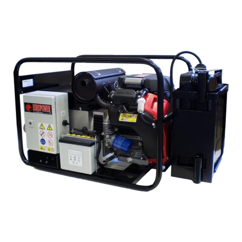
EuroPower EP30DE User manual

EUROPOWER USER MANUAL www.EUROPOWERGenerators.com
EP30DE KU/MA-EP34TDE KU/LS-EP34TDE KU/MA-EP44TDE KU/LS-EP44TDE KU/MA
Pag.1/22
Datum:29/07/2014 Rev.: 01 Uitv: LV Goedkeurder: WB Ref: EP30DE_EP34TDE_EP44TDE-110414rev01-EN
EP30DE - EP34TDE - EP44TDE
Content:
0. INTRODUCTION
1. SAFETY INSTRUCTIONS
2. CE-MARK, NOISE LABEL AND PICTOGRAMS
3. SHORT DESCRIPTION OF THE GENERATING SET
4. DESCRIPTION OF THE CONTROL PANEL
5. USE OF THE GENERATING SET
6. INCORPORATION OF THE GENERATING SET
7. PARTS LIST
8. ELECTRICAL SCHEMES
9. BUILDING-IN DIMENSIONS
10.MAINTENANCE
11.TRANSPORT AND STORAGE
12.SEARCHING FOR DEFAULTS (engine)
ORIGINAL INSTRUCTION MANUAL

EUROPOWER USER MANUAL www.EUROPOWERGenerators.com
EP30DE KU/MA-EP34TDE KU/LS-EP34TDE KU/MA-EP44TDE KU/LS-EP44TDE KU/MA
Pag.2/22
Datum:29/07/2014 Rev.: 01 Uitv: LV Goedkeurder: WB Ref: EP30DE_EP34TDE_EP44TDE-110414rev01-EN
0. INTRODUCTION
Please read this manual carefully before using the generating set. If you act as
stated in this manual, your generating set will guarantee you a smooth
functioning for years.
First read the engine and alternator manual. These manuals are supplied with
each generating set and explain the use, the maintenance and the dangers in case
of improper use.
If you have any questions concerning your generating set please contact
EUROPOWER Generators through www.europowergenerators.com.
All data in this manual are based on the standard versions of
EP30DE/EP34TDE/EP44TDE with Kubota V3300/ V3800DIT engine.
Generating sets with options can have slightly different data. Contact your
dealer for more information.
1. SAFETY INSTRUCTIONS
Read and understand the owner’s manual before using the generator, opening
it or working on it. This can prevent personal injury or equipment damage.
When this manual is not 100% clear to you, please consult an authorised
dealer.
Place the generator on a levelled surface.
When the generator is tilted, fuel spillage may result.
Place the generator, when in use, at least 1m away from buildings or other
equipment.
Keep children and pets away from the generator when it is in operation.
Diesel is extremely flammable and explosive under certain conditions.
Refuel only in a well-ventilated area with the engine stopped.
Do not smoke or allow flames or sparks in the area where the engine is
refuelled or where diesel is stored.
Wipe up spilled fuel at once.
Avoid repeated or prolonged contact with skin or breathing of vapour.
Use automotive diesel (diesel number 2 according to EN590) with a cetane
number of 40 or higher, and with a max. sulphur level of 0,5%.
It is allowed to use the generating set in the rain (according to EN60529-
protection class IP23). This means that the generating set can support
water in the form of rain till max. 60° in respect of the perpendicular
line. Do not use the generating set in the snow. Only use it in spaces
where there is no explosion hazard.
The generator is a potential source of electrical shocks when misused. Do
not operate the generator with wet hands.
Connections for standby power to a building’s electrical system must be
made by a qualified electrician and must comply with all applicable laws
and electrical codes.
Never connect the generating set to the public mains or any other
electrical power source! Improper connections can allow electrical current
from the generator to back feed into the utility lines. Such back feed may
electrocute utility company workers, and when utility power is restored,
the generator may explode, burn or cause fires in the building’s
electrical system.
The muffler becomes very hot during operation and remains hot for a while
after stopping the engine.
Be careful not to touch the muffler while it is still hot.
Let the engine cool down before storing the generator indoors.
To prevent scalding, pay attention to the warning marks attached to the
generator.

EUROPOWER USER MANUAL www.EUROPOWERGenerators.com
EP30DE KU/MA-EP34TDE KU/LS-EP34TDE KU/MA-EP44TDE KU/LS-EP44TDE KU/MA
Pag.3/22
Datum:29/07/2014 Rev.: 01 Uitv: LV Goedkeurder: WB Ref: EP30DE_EP34TDE_EP44TDE-110414rev01-EN
Keep in mind the maximum weight a person is allowed to carry if you move
the generating set by hand.
Make sure the generator operates in a well-ventilated room. In case of
insufficient cooling and/or ventilation severe damage can occur. Exhaust
gases also contain poisonous carbon monoxide.
Never use the generator when the cover plates are removed from the engine
or alternator.
Do not wear loose clothes near the generator.
Let maintenance be carried out by trained technicians only. For example,
according to art. 233 of the Belgian AREI –General Regulation on
Electrical Installations - this means that maintenance can only be carried
out by “warned persons” (code BA4) or “authorised persons” (code BA5).
If local rules differ, the most rigid of both rules should be followed.
Never work on the generator while it is still running.
Never connect appliances that need more power than the generator can
provide. This could seriously damage the generator.
Be very careful while using a welder on any type of generator. Welders
might damage the alternator. Always consult a EUROPOWER specialist first
to make sure that the power of the generating set matches the requested
power of the welder.
If the appliance you want to connect is of an electronic kind (computer,
radio, TV, plastic welder, …), always consult a EUROPOWER specialist
first. Such appliances might not work or even break down in combination
with some alternators. Alternators with a low harmonic distortion are best
suited for connection of electronic appliances.
Never let a diesel engine run for a long time (= more than 30 min.) at no
load or at a very low load (<15%). This can damage the engine severely!
2. CE-MARK, NOISE LABEL AND PICTOGRAMS
2.1. CE-marking and noise label: these are examples of a EUROPOWER type
indication plate and a noise label. The type indication plate can be found on
every generator. The noise label only appears on generators that comply with the
European Standard 2000/14/EC. More information on this can be found in the
EUROPOWER documentation or on our web site www.europowergenerators.com.
2.2. Pictograms: some of these pictograms are typical for a certain option or
special type of generating set. Therefore not all pictograms necessarily appear
on the standard generating set.

EUROPOWER USER MANUAL www.EUROPOWERGenerators.com
EP30DE KU/MA-EP34TDE KU/LS-EP34TDE KU/MA-EP44TDE KU/LS-EP44TDE KU/MA
Pag.4/22
Datum:29/07/2014 Rev.: 01 Uitv: LV Goedkeurder: WB Ref: EP30DE_EP34TDE_EP44TDE-110414rev01-EN
EP(S)WATER_D
(2)
-
Here you can fill the tank with diesel. Remove the fuel filler cap and
check the fuel level. Refuel carefully to avoid fuel spillage. Do not fill
the tank to the top. You might have to lower the fuel level, depending
on operating conditions. After refuelling, reinstall the fuel filler cap
and tighten it securely. Spilled fuel causes environmental damage.
Wipe up spilled diesel at once.
(3)
-
Diesel drain plug. By loosening this plug you can drain the fuel tank
if necessary. Spilled diesel causes environmental damage. Wipe up
spilled diesel at once. If you will not use the drained diesel again,
you have to get rid of it in a correct and environmentally friendly way.
Respect the local regulations. Do not pour diesel into the ground or
down the drain.
(4)
-
Here you can fill the oil by loosening the oil filler cap or dipstick. Fill
carefully to avoid oil spillage. Spilled oil should be wiped up
immediately in a correct and environmentally friendly way. Respect
the local regulations. Do not pour oil onto the ground or down the
drain.
(5)
-
After removing the hatch, you can refill the radiator.
Warning: risk of burns! Stop the generating set en let it cool down
before removing the pressure cap. Loosen the pressure cap to
release the pressure. Do not refill the radiator when the engine has
just run and is still warm. Wait until the engine cooled down and then
refill the radiator.
Hot coolant and steam can cause a serious and even deathly injury.
(11)
-
WARNING! –Electric shock hazard.
(12)
-
Never connect the generator to an installation which is also
connected to a public mains. Improper connections can allow
electrical current from the generator to back feed into the utility lines.
Such back feed may electrocute utility company workers, and when
utility power is restored, the generator may explode, burn or cause
fires in the building’s electrical systems.
(13)
-
Here an earth pin can be connected. Follow the instructions in this
manual concerning the use of an earth pin.

EUROPOWER USER MANUAL www.EUROPOWERGenerators.com
EP30DE KU/MA-EP34TDE KU/LS-EP34TDE KU/MA-EP44TDE KU/LS-EP44TDE KU/MA
Pag.5/22
Datum:29/07/2014 Rev.: 01 Uitv: LV Goedkeurder: WB Ref: EP30DE_EP34TDE_EP44TDE-110414rev01-EN
(22)
-
WARNING! –Hot surface. Can cause burns. Hot engine and hot
exhaust system can cause serious and even lethal injuries. Never
work on the generating set before it has sufficiently cooled down.
(23)
-
Do not smoke nor allow sparks or flames near the generating set,
the fuel pipe, the fuel filter, the fuel pump or other possible sources
of spilled fuel or fuel vapours.
(24)
-
Fuel is highly flammable and explosive and you can be burnt or
seriously injured when refuelling. Turn the engine off and let it cool
down before refuelling.
(25)
-
The engine‘s exhaust gases contain poisonous carbon monoxide.
You can be killed or seriously hurt. Do not run the engine in a closed
environment. The exhaust system should be leak-tight and it should
be inspected regularly.
(26)
-
Rotating parts can cause serious and even deathly injuries. Do not
let the engine run unless all protection covers, shields and grids are
in place.
Make sure the incoming and outgoing air flow is not obstructed.
(27)
-
Only use a hoist according to local safety regulations.
Never allow sharp bends in lifting cables and chains.
It is strictly forbidden to dwell or stay in the risk zone under a lifted
load. Never lift the unit over people or residential areas. Never leave
a load hanging on a hoist. Lifting acceleration and retardation shall
be kept within safe limits.
To lift heavy parts, a hoist of ample capacity, tested and approved
according to local safety regulations, shall be used.
Lifting hooks, eyes, shackles, etc. shall never be bent and shall only
have stress in line with their design load axis.
The capacity of a lifting device diminishes when the lifting force is
applied at an angle to its load axis.
For maximum safety and efficiency of the lifting apparatus all lifting
members shall be applied as near to perpendicular as possible.
A hoist has to be installed in such a way that the object will be lifted
perpendicular.
If that is not possible, the necessary precautions must be taken to
prevent load-swinging, e.g. by using two hoists, each at
approximately the same angle not exceeding 30° from the vertical.

EUROPOWER USER MANUAL www.EUROPOWERGenerators.com
EP30DE KU/MA-EP34TDE KU/LS-EP34TDE KU/MA-EP44TDE KU/LS-EP44TDE KU/MA
Pag.6/22
Datum:29/07/2014 Rev.: 01 Uitv: LV Goedkeurder: WB Ref: EP30DE_EP34TDE_EP44TDE-110414rev01-EN
(28)
-
WARNING! –Consult the instruction and maintenance manual of the
engine and the alternator before carrying out maintenance.
Improper maintenance, or failure to correct a problem before
operation, can cause a malfunction in which you can be seriously
hurt or killed.
Always follow the inspection and maintenance recommendations
and schedules mentioned in the instruction and maintenance
manual of the engine and the alternator.

EUROPOWER USER MANUAL www.EUROPOWERGenerators.com
EP30DE KU/MA-EP34TDE KU/LS-EP34TDE KU/MA-EP44TDE KU/LS-EP44TDE KU/MA
Pag.7/22
Datum:29/07/2014 Rev.: 01 Uitv: LV Goedkeurder: WB Ref: EP30DE_EP34TDE_EP44TDE-110414rev01-EN
3. SHORT DESCRIPTION OF THE GENERATING SET
EP30DE
EP34TDE
EP44TDE
GENERATING SET:
Power
Unit
3-phase (400V)
Max. power @ Cos0,8
kVA / kW
-
33 / 26,4
44 / 35.2
Max. current
A
-
38
51
Cont. power @ Cos0,8
kVA / kW
-
30 / 24
40 / 32
Cont. current
A
-
34
46
1-phase (230V)
Max. power
kVA / kW
30 / 30
10.5 / 10.5
14 / 14
Max. current
A
130
46
61
Cont. power
kVA / kW
28 / 28
10.5 / 10.5
14 / 14
Cont. current
A
122
46
61
Voltage 3/ 1
V
230
400/230
400/230
Frequency
Hz
50
Dimensions L x W x H
cm
160 x 96 x 105
Weight
(oil and coolant incl.)
kg
…
… (LSA42.3) /
640(ECP28)
666(LSA42.3) /
725(ECP32)
Noise level measured
(75% charge) guaranteed*
dB(A)@
7m
LWA
79
*
77
*
79
*
Tank
litre
76
Autonomy at charge of
75%
hour
10
12.5
10
Battery
V / Ah
12 / 88
Engine protections
In case of low oil pressure, high water temperature, breaking of the fan belt
or damaged 12V alternator, (low fuel level)**
ENGINE:
Type
KUBOTA
V3800DIT
KUBOTA V3300
KUBOTA
V3800DIT
Number of revolutions
rpm
1500
Power stand-by
kW
42
27.5
42
Displacement
cm³
3769
3318
3769
Consumption at full load
litre/hour
7.7
6.1
7.7
Oil capacity
litre
13,2
Coolant capacity
litre
9,3
ALTERNATOR:
Type
Version with Mecc-
Alte: ECP32-3S/4
with AVR
(brushless)
Version with
Leroy-Somer:
LSA42.3VS3
AREP with AVR
SYS.2 (brushless)
Version with Mecc-
Alte: ECP28-VL/4
with AVR
(brushless)
Version with
Leroy-Somer:
LSA42.3S5 AREP
with AVR SYS.2
(brushless)
Version with Mecc-
Alte: ECP32-3S/4
with AVR
(brushless)
(*)This generating set does not comply with the European Noise Directive
2000/14/EG: see also “Mounting instructions” to be found with “Declaration of
Incorporation according to 2006/42/EG”.

EUROPOWER USER MANUAL www.EUROPOWERGenerators.com
EP30DE KU/MA-EP34TDE KU/LS-EP34TDE KU/MA-EP44TDE KU/LS-EP44TDE KU/MA
Pag.8/22
Datum:29/07/2014 Rev.: 01 Uitv: LV Goedkeurder: WB Ref: EP30DE_EP34TDE_EP44TDE-110414rev01-EN
** See chapter 4 Description of the control panel
The main components of the generating set are: the water-cooled KUBOTA diesel
engine (1500rpm), the alternator, the control panel, the ECU (electronic control
unit –only on EP30DE / EP44TDE), integrated fuel tank and the chassis.
For engine and alternator specifications we refer to the engine and alternator
manual supplied with each generating set.
Specifications for the control panel can be found in chapter 4.
The Kubota V3800DIT engine (only on EP30DE / EP44TDE) has an electronic speed
regulation. The ECU will compare the engine speed coming from the speed sensor
to a reference speed that has been determined in advance (1500rpm). If necessary
it will activate the actuator by means of a pulsating signal. This way, the
engine speed remains stable at 1500 rpm.
The ECU also takes care of the starting procedure (automatic preheating time,
activation time of the starting motor, start interruption with running engine),
it has an emergency stop function (when the speed is too high, the oil pressure
is too low, the coolant temperature is too high and the charging current of the
battery is too low or when the battery is broken (= battery charging control))
and a failure diagnosis function (by means of signal lamps).
The chassis of the generator serves as fuel tank (content 76 litres) and
contains the fuel filler cap, the mechanic fuel level meter, the fuel drain cap
(for cleaning of fuel tank), 4 fixation holes (for fixed mounting of the
genset), the battery support and the fixing support for the (manual) oil drain
pump. In the bottom plate of the chassis there is an inspection hole for the oil
drain screw on the crank case cover.
4. DESCRIPTION OF THE CONTROL PANEL
The control panel consists of:
DSE4420 control module (1)
Emergency stop (2)
The control panel consists of:
Relay 12V/70A (EP30DE/44TDE) +
relay 12V/30A (A)
1
2
3
4
5
6
6
A
B
C
D
E
F
G
H
I

EUROPOWER USER MANUAL www.EUROPOWERGenerators.com
EP30DE KU/MA-EP34TDE KU/LS-EP34TDE KU/MA-EP44TDE KU/LS-EP44TDE KU/MA
Pag.9/22
Datum:29/07/2014 Rev.: 01 Uitv: LV Goedkeurder: WB Ref: EP30DE_EP34TDE_EP44TDE-110414rev01-EN
Contact switch with 3 positions
"REMOTE AUTO START/OFF/MAN START"
with removable key. In position
"MAN START" you cannot start the
generating set through a remote
switch. To start through a remote
switch, put the key in position
"REMOTE AUTO START".
Red button: failure button
(EP30DE/44TDE) (4)
Pilot lamp yellow: failure button
(EP30DE/44TDE) (5)
Sockets (6):
EP30DE: 1 x schuko 16A 230V + 1 x
3p CEE 63A 230V
EP34TDE: 1 x 3p CEE 63A 230V + 1 x
5p CEE 63A 400V
EP44TDE: 1 x 3p CEE 63A 230V + 1 x
5p CEE 63A 400V
Thermal-magnetic protections (B)
Earth leakage protection (earth
pin included) (C)
12V fuse 50A (start circuit) +
100A (Kubota glow relay) (D)
ECU (Electronic Control Unit)
(EP30DE/44TDE) (E)
Relay 12V/100A (Kubota glow
relay) (EP30DE/44TDE) (F)
230V AC fuses 2A (3x) (G)
12V fuses 5A and 15A
(EP30DE/EP44TDE) + 5A and 40A
(2x) (EP34TDE) (H)
Connector remote control (I)
On the control panel of the EP30DE/EP34TDE/EP44TDE there is space left for the
optional mounting of:
1 frequency meter and 3 amp. meters (for the EP30DE 1 amp. meter)
modular insulation protection control relay (instead of earth leakage
protection)
For generating sets with options (e.g. volt meter selector switch (not for
EP30DE), automatic start/stop system, star-delta switch (not for EP30DE) …)
there can be small differences! Please contact your dealer for info on parts for
these options. Other options are only possible if mounted when generator is
being built, not afterwards.

EUROPOWER USER MANUAL www.EUROPOWERGenerators.com
EP30DE KU/MA-EP34TDE KU/LS-EP34TDE KU/MA-EP44TDE KU/LS-EP44TDE KU/MA
Pag.10/22
Datum:29/07/2014 Rev.: 01 Uitv: LV Goedkeurder: WB Ref: EP30DE_EP34TDE_EP44TDE-110414rev01-EN
4.1. Nr. 1: Control module DSE4420 with key switch:
Below you can find a short explanation about the DSE4420 control module.
Picture 2.
Description LED lights 1 to 7 (Picture 2) on DSE4420 control module.
Nr.
Description
1
Red LED lights up when output voltage of generating set is available.
2
Red LED will light up together with LED 1 when generating set is
connected to the load.
3
Red LED will light up after you pressed the green button “I”.
4
Red LED will light up when the control module is in AUTO mode.
5
(optional) Red LED will light up when mains is connected to the load.
6
(optional) Red LED lights up when mains is available.
7
Red LED, warning/alarm indicator. This LED will light up when the
DSE4420 has detected a warning or an alarm.
-Remark: The generating set can be started in two ways:
o1. With the key switch (item 3, Picture 17) in position "MAN START".
In this position you should press the green button "I" once to start
the generating set. Automatic starting trials (maximum 9) will be
executed. In position "MAN START" the generator cannot be started
via an external contact remotely. To do this, you have to put the
key switch in position "REMOTE AUTO START".
Main status display
Display scroll button
Off (0) - AUTO - ON (1)
Information button
1
2
3
6
5
4
7

EUROPOWER USER MANUAL www.EUROPOWERGenerators.com
EP30DE KU/MA-EP34TDE KU/LS-EP34TDE KU/MA-EP44TDE KU/LS-EP44TDE KU/MA
Pag.11/22
Datum:29/07/2014 Rev.: 01 Uitv: LV Goedkeurder: WB Ref: EP30DE_EP34TDE_EP44TDE-110414rev01-EN
o2. With the ignition key in position "REMOTE AUTO START". The
generating set can be started via an external contact at a distance.
The generating set itself will also undertake maximal 9 attempts to
start. LED (Nr.4) next to the "AUTO" button will light up as soon as
the “AUTO” mode has been activated.
-The generating set can be stopped (with the ignition key in position “MAN
START”) by pressing the red button "0" once. Do not forget to turn the key
switch to position "0". By doing so, you cut off the power supply from the
DSE4420 control module.
-With the key switch in position "REMOTE AUTO START", the external contact
will give a signal to the DSE4420 control module to stop the generating
set. The generating set can be stopped as well by pressing the red button
“0” in “AUTO” mode.
-By pressing the scroll button you can browse the following
parameters:
oCheck voltage between phase and zero and between phases (not for
EP30DE)
oFrequency
orpm
orunning hours of the generating set
obattery voltage
o24h clock (automatic reset when voltage is taken away from DSE4420).
-Views on status display: the status display is divided in following
subareas:
Inst.
icon
Instrumentation
Units
Alarm
icon
Active
config
/FPE,
event
index
Instrumentation
Units
Mode
icon
Instrumentation
Units
oMeasured value icon
Icon
Graphic
Details
Generator
Generator voltage and Hz.
Engine speed
Engine speed (only with electronic speed
governor EDC4).
Hours run
Engine running hours.
Battery voltage
Measured battery voltage.
Instrumentation
icon (1).
Active
configuration (2).
Instrumentation +
units (3 + 4).
Mode icon (6).
1
2
3
4
5
6
5
Picture 3.

EUROPOWER USER MANUAL www.EUROPOWERGenerators.com
EP30DE KU/MA-EP34TDE KU/LS-EP34TDE KU/MA-EP44TDE KU/LS-EP44TDE KU/MA
Pag.12/22
Datum:29/07/2014 Rev.: 01 Uitv: LV Goedkeurder: WB Ref: EP30DE_EP34TDE_EP44TDE-110414rev01-EN
Engine
temperature
Measured cooling water temperature.
Oil pressure
Measured oil pressure.
Event log
Appears when the event log is being
displayed.
oMode icon:
Icon
Graphic
Details
Auto
Appears when the engine is at rest and
the unit is in auto mode.
By pushing the button (information), you can switch from the parameter
screen to the event log.
By pushing the button you go back to the previous screen. The most recent
event is shown first. When you switch from parameter screen to event log, it is
always the most recent event which is shown first.
In the left corner underneath the event log screen, you can see the number of
the event which is shown on the screen.
Only the last 5 events are saved in the DSE4420 module.
Example of engine stop alarm displayed on event log screen:
-When there is a warning/alarm, the indicator led will light up. The
general status screen will show one of the icons from the table
underneath. When there are multiple alarms, they are shown alternatively
on the status screen.
Icon
Description
External input alarm
Auxiliary Digital inputs can be user
configured as Digital inputs and will
display the relevant icon.
Fail to start
The engine doesn't start after maximum 9
starting attempts.
Fail to stop
The module has detected a condition that
indicates that the engine is running when
it has been instructed to stop.
External input
alarm 1.
Number of engine running hours
when the
event was logged (99hrs 9mins).
Event log icon.
Event number.
Picture 4.

EUROPOWER USER MANUAL www.EUROPOWERGenerators.com
EP30DE KU/MA-EP34TDE KU/LS-EP34TDE KU/MA-EP44TDE KU/LS-EP44TDE KU/MA
Pag.13/22
Datum:29/07/2014 Rev.: 01 Uitv: LV Goedkeurder: WB Ref: EP30DE_EP34TDE_EP44TDE-110414rev01-EN
Low Oil Pressure Warning
The module detects that the engine oil
pressure has fallen for more than 10 sec.
below the low oil pressure alarm setting
level.
High Coolant Temperature
Warning
The module detects that the engine coolant
temperature has exceeded for more than 10
sec. below the high engine temperature
alarm setting level.
Under speed warning (only
for electronic speed
governor - EDC4)
The engine speed has fallen for more than
10 sec. below the underspeed alarm setting.
Over speed warning (only
for electronic speed
governor - EDC4)
The engine speed has risen above 1710rpm.
Charge alternator failure
The charge alternator voltage is to low,
measured on the L/D+ connection on the
alternator. De used values are: 6V (12V
system) / 12V (24V system).
Low fuel level sensor
Only on 24V system. The low fuel level
sensor has detected that the fuel level has
fallen below a pre-set value. Still 10% of
the fuel tank is filled. The generating set
will not be shut down.
On 12V system, the orange lamp on the fuel
level meter (item 4, Picture 15) will light
up.
Battery low/high voltage
The battery voltage is to low/high
following a pre-set value.
Under voltage: 12V > 1min. / 24V > 1min.
Over voltage: 14,6V > 1min. / 29,2V > 1min.
Alternator low voltage
shutdown
The alternator output voltage has fallen
for more than 10 sec. below the pre-set
alarm setting.
Alternator high voltage
shutdown
The alternator output voltage has risen for
more than 10 sec. above the pre-set alarm
setting.
Under Frequency Shutdown
The alternator under frequency has fallen
for more than 10 sec. below the pre-set
alarm setting.
Over Frequency Shutdown
The alternator over frequency has risen for
more than 10 sec. above the pre-set alarm
setting.
Emergency Stop
The emergency button is pushed in.
This is a failsafe (normally closed to
battery negative) input and will
immediately stop the generating set should
the signal be removed from digital input A.
PAY ATTENTION: The emergency stop negative
signal must be present at digital input A
on the module DSE4420, otherwise the
generating set will shut down.
CAN ECU Data fail (only
for electronic speed
governor - EDC4)
The module is configured for CAN operation
and does not detect data on the engine Can
data link, the engine shuts down.
CAN ECU Shutdown
The engine ECU has detected a shutdown

EUROPOWER USER MANUAL www.EUROPOWERGenerators.com
EP30DE KU/MA-EP34TDE KU/LS-EP34TDE KU/MA-EP44TDE KU/LS-EP44TDE KU/MA
Pag.14/22
Datum:29/07/2014 Rev.: 01 Uitv: LV Goedkeurder: WB Ref: EP30DE_EP34TDE_EP44TDE-110414rev01-EN
warning/alarm (only for
electronic speed governor
- EDC4)
alarm/warning and has informed the DSE4420
module of this situation. The exact error
is also indicated on the DSE4420 module’s
display.
Error report on main status
display
Description
Low fuel level switch
Picture 5.
When the fuel tank level is under the
minimum level for more than 5 sec., the
DSE4420 module will shut down the generator
automatically. The error code as shown on
the left will appear together with a red
exclamation mark. You need to refuel before
starting again. In case you start without
refueling, the generator will automatically
stop after 7 seconds.
Low coolant level switch.
Picture 6.
When the level of the cooling liquid goes
below the minimum level for more than 5
seconds, the DSE4420 module will turn off
the engine. The error code as shown on the
left will appear together with a red
exclamation mark. You need to refill the
cooling liquid before starting again. In
case you start without refueling, the
generator will automatically stop after 7
seconds.
-You have to differentiate between warnings and critical alarms.
oWarnings: will not affect the operation of the generating set. They
serve to draw the operator’s attention to an undesirable condition.
Warnings will not stop the engine.
The following warning can occur:
Engine alternator charge failure
You can eliminate the warning by switching the OFF-ON button to the
OFF position, and by switching it back to the ON position after a
few seconds.
oCritical alarms: will stop the engine and will draw the operators
attention to an undesirable condition. These critical alarms have to
be examined and have to be solved. Afterwards the DSE3110 module has
to be reset.
The following critical warnings can occur:
Low oil pressure
High engine temperature
Generator under voltage
Generator over voltage
Generator under frequency
Generator over frequency
Emergency stop
Low fuel level
You can eliminate the critical warning by switching the OFF-ON
button to the OFF position, and by switching it back to the ON
position after a few seconds.
-When you start the generator through the green button "I" or through an
external contact (remote), the DSE4420 module will start its program. The
DSE4420 module will first check whether there are critical alarms or not.
During this process you can see the following moving icon:

EUROPOWER USER MANUAL www.EUROPOWERGenerators.com
EP30DE KU/MA-EP34TDE KU/LS-EP34TDE KU/MA-EP44TDE KU/LS-EP44TDE KU/MA
Pag.15/22
Datum:29/07/2014 Rev.: 01 Uitv: LV Goedkeurder: WB Ref: EP30DE_EP34TDE_EP44TDE-110414rev01-EN
-The DSE4420 module executes a maximum of 9 starting attempts.
-When there are no alarms after starting the generator, the display will
show the icon of a moving engine underneath:
4.2. Thermal magnetic protections:
Each socket is protected separately. See electrical scheme.
on the type indication plate of the generator you can find more
information about the power/maximum admissible charging current of the
generator.
in case of overload, the thermal-magnetic protection in the control panel
shall be switched off after a short period of time. Check the load, reduce
it if necessary and switch on the thermal-magnetic protection again.
in case of short-circuit, the thermal-magnetic protection will switch off
immediately! Check what caused the short-circuit and switch on the protection
again afterwards.
4.3. Earth leakage protection:
The earth leakage protection cuts a circuit automatically in case there is a
leakage between phase and earth during a preset time.
The earth leakage protection protects people (users) against electric shocks
when they are in direct contact. For more explanation in relation to the earth
leakage breaker and settings we refer to chapter 5.8. Safety for the users.
4.4. Connector remote control:
This standard 4 pole connector (on picture 1) can be used to start the generator
from a distance. Turn the screw cap loose and connect the male connector
(supplied loose) to the female connector.
5. USE OF THE GENERATING SET
CAUTION! The generating sets EP30DE/34TDE/44TDE are equipped with a 12V
electric fuel pump. This pump may not “run dry”. If the engine stops because of
fuel deficiency, turn the contact key to position “OFF” as fast as possible.
5.1 Before starting:
-Check the oil level.
-Check the fuel level.
-Check the coolant level in the expansion tank.
-Make sure the emergency stop is unlocked.
-Make sure the charge is disconnected.
-Make sure the fuel cock is open. You can find this fuel cock on the water
separator.
Picture 7.
Picture 8.

EUROPOWER USER MANUAL www.EUROPOWERGenerators.com
EP30DE KU/MA-EP34TDE KU/LS-EP34TDE KU/MA-EP44TDE KU/LS-EP44TDE KU/MA
Pag.16/22
Datum:29/07/2014 Rev.: 01 Uitv: LV Goedkeurder: WB Ref: EP30DE_EP34TDE_EP44TDE-110414rev01-EN
OPEN
CLOSED
5.2. Starting the generating set:
-Starting on the generator itself:
oPut the 3-position key switch in position "MAN START".
oPush the green button "I" on the control module DSE4420.
oThe control module DSE4420 will start the engine automatically
(maximum 9 starting attempts).
-Starting via an external contact (at distance):
oMake sure that the remote control connector (item 9, Picture 15) is
connected.
oPut the 3-position key switch in position "REMOTE AUTO START".
oThe control module DSE4420 will start the engine automatically
(maximum 9 starting trials).
oLet the engine warm up for a couple of minutes before charging the
generating set.
oConnect the charges.
5.3. Charging the generating set:
-Let the engine run for 5 minutes to warm up before charging.
-On the type label of the generating set you can find the current data/
admitted power charge of the generating set.
-In case of overload, the thermal-magnetic protection, mounted in the
control panel, shall switch off after a short time. Check and reduce the
charges if necessary. Switch on the protection afterwards.
-In case of short-circuit, the thermal-magnetic protection shall switch off
immediately! Try to find out the cause of the short-circuit. Switch on the
protection afterwards.
-Never let the diesel engine run for a long time (= more than 30 min.) at
no load or at a very low load (<15%). This can damage the engine severely.
-Check the voltages, frequency and currents regularly.
5.4. Stopping the generating set:
-Disconnect the charge.
-Before stopping the generating set, let the engine run for a few minutes
at no load to cool down.
-Stopping on the generator itself:
oStop the generating set by pressing the red button “0” on the
DSE4420 control module once.
oPut the key switch with three positions in position “0” when the
generating set has stopped.
-Stopping via an external contact (at distance):
oThe external contact will give a signal to the DSE4420 control
module to stop the generating set when the key switch is in position
“REMOTE AUTO START”. The generating set also can be stopped in
position “AUTO” through the red button “0”.

EUROPOWER USER MANUAL www.EUROPOWERGenerators.com
EP30DE KU/MA-EP34TDE KU/LS-EP34TDE KU/MA-EP44TDE KU/LS-EP44TDE KU/MA
Pag.17/22
Datum:29/07/2014 Rev.: 01 Uitv: LV Goedkeurder: WB Ref: EP30DE_EP34TDE_EP44TDE-110414rev01-EN
5.5. Cooling:
-Make sure the aspiration of cooling air by the engine and alternator is
not obstructed.
-Make sure the warm engine and alternator cooling air and the exhaust gases
can be adrifted freely.
-Make sure the generator operates in a well-ventilated room!
5.6. Protections:
-Engine: low oil level protection, cooling water temperature protection,
overspeed, low battery charging current and starting protection.
-Alternator: thermal-magnetic protection and earth leakage protection.
5.7. Maintenance (see also chapter 10):
All maintenance points (air filter, oil drain, oil fill cap, oil filter,
fuel filters/water separator, radiator filler cap, expansion tank) are very
good accessible. For normal maintenance activities, check the engine
manual. In case of engine or alternator defect, consult your EUROPOWER
dealer.
5.8. Safety for the users:
The standard version of the generating set is delivered with earth leakage
protection and thermal-magnetic protection and is connected following the
IU electrical scheme.
This means that for connection of charges class 1 (charges with earth) and
for charges class 2 (charges with double insulation, to be recognized by
the “double square” pictogram on the machine) there is no limitation in the
quantity of charges connected at the same time on the generating set.
Contact your distributor for details on the above subject.
Still you have to respect the minimum square (mm²) and maximum length of
the cables you are using (switching off of the thermal-magnetic protection
in case of short-circuit).
The working of the earth leakage protection can only be guaranteed if the
added earth pin with 4 metres of earthing cable is connected to the
generating set (see symbol ‘earthing’ on the generating set). The earth pin
has to be drawn into the soil completely to guarantee a good functioning.
The spreading resistance of the earth electrode has to be measured by a
recognized organism.
Table: Recommendation of minimum cable section (in mm²) and maximum cable
length (in m) in function of the current (in A):
Cable length
Cable length
Cable length
Current (A)
0 - 50 meter
> 50 - 100 meter
> 100 - 150 meter
6
1.5mm²
1.5mm²
2.5mm²
8
1.5mm²
2.5mm²
4mm²
10
2.5mm²
4mm²
6mm²
12
2.5mm²
6mm²
10mm²
16
2.5mm²
10mm²
10mm²
18
4mm²
10mm²
10mm²
24
4mm²
10mm²
16mm²
26
6mm²
16mm²
16mm²
36
6mm²
25mm²
25mm²
50
10mm²
25mm²
35mm²

EUROPOWER USER MANUAL www.EUROPOWERGenerators.com
EP30DE KU/MA-EP34TDE KU/LS-EP34TDE KU/MA-EP44TDE KU/LS-EP44TDE KU/MA
Pag.18/22
Datum:29/07/2014 Rev.: 01 Uitv: LV Goedkeurder: WB Ref: EP30DE_EP34TDE_EP44TDE-110414rev01-EN
6. INCORPORATION OF THE GENERATING SET
Consult your EUROPOWER dealer or EUROPOWER Generators.
See the “Mounting instructions” to be found with “Declaration of Incorporation
according to 2006/42/EG” for generating sets that do not have the EC Declaration
of Conformity IIA.
7. PARTS LIST
This parts list is based on the standard versions of the EP30DE –EP34TDE -
EP44TDE. For generating sets with options (e.g. insulation protection, remote
control, automatic start/stop system, …) there can be small differences! Please
contact your dealer for info on parts for these options.
7.1
GENERATOR
Article n°
Description
100002000
FUEL LEVEL METER G/LL43/435 6/4”
110000015
RUBBER DRAIN CAP RADIATOR
120140200
SILENT BLOC BRB110 M12
169850115
BATTERY CABLE + L=1150mm, 50mm² COMPLETE
169950045
BATTERY CABLE –L=450mm, 50mm² COMPLETE
169999983
BATTERY 88Ah 12V MAINTENANCE FREE
170001014
SUCTION HOSE AIR FILTER (EP30DE/44TDE)
170001015
TUBE L = 70mm, DIA.EXT.60mm
170001020
TUBE L = 150mm, DIA.EXT.60mm (EP30DE/44TDE)
170001090
SUCTION HOSE AIR FILTER (EPS34TDE)
185400061
EXHAUST dia. 50/40mm/31-50HP (EP34TDE)
185400067
EXHAUST dia. 60/50mm/50-68HP (EP30DE/44TDE)
186001000
OIL DRAIN PUMP
186001001
HOSE FOR OIL DRAIN PUMP
186001005
ADAPTER M12X1.25 INSIDE M22X1.5 OUTSIDE for 186001001
186001006
BANJO BOLT M12 * 1.25
186001007
METAL SEAL WITH RUBBER 22*29mm
201110322
LEROY SOMER ALTERNATOR LSA42.3VS3 –SYSTEM 2 (EP34TDE KU/LS2)
201110402
LEROY SOMER ALTERNATOR LSA42.3S5 –SYSTEM 2 (EP44TDE KU/LS2)
202141030
MECC ALTE ALTERNATOR ECP28-VL/4 (EP34TDE KU/MA)
202151040
MECC ALTE ALTERNATOR ECP32-3 S/4 (EP30DE/44TDE KU/MA)
301110401
KUBOTA ENGINE V3300 1500tpm (EP34TDE)
301110601
KUBOTA ENGINE V3800DIT 1500tpm (EP30DE/44TDE)
910000023
TREADED BAR M6-ZN L=240mm
910000025
U-PROFILE ALU 15*15mm L=400mm
910000242
CHASSIS
910999570
FAN PROTECTION PART 2
910999591
FILLING MATERIAL 65mm ALTERNATOR (EP34TDE KU/MA)
910999592
FILLING MATERIAL 45mm ALTERNATOR (EP34TDE KU/LS2)
910999595
FILLING MATERIAL 25mm ALTERNATOR (EP30DE/44TDE KU/MA)
910999535
ENGINE SUPPORT LEFT
910999536
ENGINE SUPPORT RIGHT
910999602
FAN PROTECTION PART 1
910999741
RADIATOR SUPPORT LEFT
910999742
RADIATOR SUPPORT RIGHT
910999810
EXTERIOR PROTECTION GRID RADIATOR
910999831
SUPPORT DIESEL PUMP
910999934
AIR FILTER SUPPORT

EUROPOWER USER MANUAL www.EUROPOWERGenerators.com
EP30DE KU/MA-EP34TDE KU/LS-EP34TDE KU/MA-EP44TDE KU/LS-EP44TDE KU/MA
Pag.19/22
Datum:29/07/2014 Rev.: 01 Uitv: LV Goedkeurder: WB Ref: EP30DE_EP34TDE_EP44TDE-110414rev01-EN
914000031
CONTROL PANEL EP30TDE COMPLETE
914000034
CONTROL PANEL EP34TDE COMPLETE
914000044
CONTROL PANEL EP44TDE COMPLETE
A109
DIESEL PUMP 12VDC
A172
WATER SEPARATOR
7.2
CONTROL PANEL
170000037
FUSE 40 A U/S EL CONNEX (EPS34TDE)
170000038
FUSE HOLDER FOR FUSE 60/80ª (EP30DE/44TDE)
170000045
FUSE 15 A U/S EL CONNEX (EP30DE/44TDE)
170000047
FUSE 5 A U/S EL CONNEX
170000096
RELAY 12V –70A NO (EP30DE/44TDE)
170000099
RELAY 12V - 30A MAKE-AND-BREAK CONTACT
170000156
FUSE 50A U/S EL CONNEX (EP30DE/44TDE)
170000157
FUSE 100A U/S EL CONNEX (EP30DE/44TDE)
170000250
RAIL CLAMP FOR FUSE US-EL C. 1-40A
170000251
COVER PLATE FOR RAIL CLAMP 170000250
174001350
DIN RAIL L = 350mm
175001026
CANOPY 500x400x155mm
180000000
SCHUKO SOCKET (EP30DE)
180995000
FUSEHOLDER FOR FUSE 180995001
180995001
FUSE 2A FOR FUSEHOLDER 180995000
180999900
RAIL CLAMP SPRING PRESSURE 0.5 - 4mm²
180999901
RAIL CLAMP SPRING PRESSURE 1.5 - 6mm²
180999915
BRIDGE (2-way) INSULATED FOR 180999900
180999918
BRIDGE (2-way) INSULATED FOR 170000250
180999995
RAIL CLAMP 35mm2 EARTHING
180999999
RAIL CLAMP 35mm2 (EP30DE)
181000000
RAIL CLAMP 6mm2
181000002
RAIL CLAMP 10mm2 (EP30DE/44TDE)
181000003
RAIL CLAMP 16mm2 (EP30DE/44TDE)
181000008
END CLAMP for DIN RAIL
181001016
THERMAL-MAGNETIC PROTECTION 2P 16A C-characteristic (EP30DE)
181001032
THERMAL-MAGNETIC PROTECTION 2P 32A C-characteristic (EP34TDE)
181001040
THERMAL-MAGNETIC PROTECTION 2P 40A C-characteristic (EP44TDE)
181001063
THERMAL-MAGNETIC PROTECTION 2P 63A C-characteristic (EP30DE)
181001100
THERMAL-MAGNETIC PROTECTION 2P 100A C-characteristic (EP30DE/44TDE)
181002607
LED COMPLETE 12V AC/DC YELLOW IP65 (max. 20mA) (EP30DE/44TDE)
181002632
EMERGENCY BUTTON RED
181002633
ADAPTOR
181002635
BUTTON RED (without adaptor) (EP30DE/44TDE)
181002638
SWITCH 3 POSITIONS + 2 KEYS (without adaptor)
181002639
CONTACT NC
181002640
CONTACT NO
181004032
THERMAL-MAGNETIC PROTECTION 4P 32A C-characteristic (EP34TDE)
181004040
THERMAL-MAGNETIC PROTECTION 4P 40A C-characteristic (EP44TDE)
181001124
CUT-OUT COIL FOR THERMAL PROTECTION (EP30DE)
181030363
SOCKET CEE 3P 63A 230V STRAIGHT
181030563
SOCKET CEE 5P 63A 400V STRAIGHT (EP34/44TDE)
183000009
EARTH LEAKAGE PROTECTION 4P 40A 30mA 6kA (EP34TDE)
183000022
EARTH LEAKAGE PROTECTION 4P 63A 30mA 6kA (EP44TDE)
183000040
EARTH LEAKAGE PROTECTION ADJUSTABLE 30mA-30A, 0-10 sec (EP30DE)
183000042
TOROIDAL CURRENT TRANSFORMER FOR 183000040 (EP30DE)
208000013
DEEP SEA DSE4420 ENGINE CONTROL MODULE
910999728
SUPPORT ECU (EP30DE/44TDE)
A13800003
GLOW RELAY 12V-100A FOR V3800DIT (EP30DE/44TDE)

EUROPOWER USER MANUAL www.EUROPOWERGenerators.com
EP30DE KU/MA-EP34TDE KU/LS-EP34TDE KU/MA-EP44TDE KU/LS-EP44TDE KU/MA
Pag.20/22
Datum:29/07/2014 Rev.: 01 Uitv: LV Goedkeurder: WB Ref: EP30DE_EP34TDE_EP44TDE-110414rev01-EN
7.3
MAINTENANCE PARTS
130000016
FUEL PRE-FILTER DIA. 8mm (11µm)
398013300
AIR CLEANER ELEMENT INNER ELEMENT
398013301
AIR CLEANER ELEMENT OUTER ELEMENT
398110000
FILTER ELEMENT for WATER SEPARATOR
398111703
FUEL FILTER ELEMENT
398213300
OIL FILTER
A13300001
VALVE COVER SEAL (EP34TDE)
A13800001
FAN BELT
A13800002
VALVE COVER SEAL (EP30DE/44TDE)
8. ELECTRICAL SCHEMES
See the EUROPOWER electrical schemes and the alternator manual enclosed.
9. BUILDING-IN DIMENSIONS
See enclosed drawing
10. MAINTENANCE
10.1. Alternator:
The alternators are maintenance-free. A periodic check of the alternator is not
necessary. A regular visual control of the different alternator parts –and
especially of the rotor bearing - at every engine maintenance is enough.
10.2. Engine:
See engine manual for maintenance intervals.
- In the factory, the engine has been filled with coolant for usage up to -30°C.
The specification of this coolant is BS6580/92 –SAE J1034.
Only use coolant with this specification!
- In the factory, the engine has been filled with 15W40 oil (for temperatures up
to -10°C).The minimum specification of this oil has to be API SJ/CF-4.
- If the ambient temperature is lower, 10W40 oil (up to -20°C) or 5W40 oil
(up to -30°C) should be used. Here the minimum specification also has to be
API SJ/CF-4.
11. TRANSPORT AND STORAGE
To prevent fuel spillage when transporting or during temporary storage, the
generator should be secured upright in its normal operating position, with the
engine switch in position “OFF”.
When transporting the generators:
Close the fuel cock (if there is any)
Do not overfill the tank (there may not be any fuel in the filler neck).
Do not use the generator while it is placed in a vehicle.
Take the generator off the vehicle and use it in a well-ventilated place.
Before storing the unit for an extended period ( > 2 months):
Make sure the storage area is free of excessive humidity and dust.
BOVENZIJD
E
This manual suits for next models
2
Table of contents
Other EuroPower Portable Generator manuals
Popular Portable Generator manuals by other brands
Siemens
Siemens SINAMICS S120 Equipment manual

Black Max
Black Max BM10500 Series Operator's manual
Linz electric
Linz electric SPW10 AC Operation and maintenance
Vante
Vante 4600 instruction manual

HOESCH
HOESCH Comfort Planning, installation and operating manual
Mase Generators
Mase Generators IS 10 T Use and maintenance manual
