EuroPower EP10000E H/MA User manual

www.EUROPOWERgenerators.com
EP10000E-EP12000TE-IP54-EP13500TE-EP12000E-EP16000TE-
EP14000E-EP18000TE
Pg. 1 / 13
Doc.nr.:0004598
Opsteller: MH Revisie:02 Revisor: BL
Opsteldatum: 15/04/2020 Goedkeurder: GD Revisiedatum: 28/06/2021
EP10000E H/MA –EP12000TE-IP54 H/So
EP12000TE-IP54 H/GTS–EP13500TE H/S
EP12000E H/S –EP16000TE H/S
EP14000E H/S –EP18000TE H/S
Content:
0. INTRODUCTION
1. SAFETY INSTRUCTIONS
2. CE-MARK, NOISE LABEL AND PICTOGRAMS
3. SHORT DESCRIPTION OF THE GENERATING SET
4. DESCRIPTION OF THE CONTROL PANEL
5. USE OF THE GENERATING SET
6. INCORPORATION OF THE GENERATING SET
7. PARTS LIST
8. ELECTRICAL SCHEMES
9. BUILDING-IN DIMENSIONS
10.MAINTENANCE
11.TRANSPORT AND STORAGE
ORIGINAL INSTRUCTION MANUAL

www.EUROPOWERgenerators.com
EP10000E-EP12000TE-IP54-EP13500TE-EP12000E-EP16000TE-
EP14000E-EP18000TE
Pg. 2 / 13
Doc.nr.:0004598
Opsteller: MH Revisie:02 Revisor: BL
Opsteldatum: 15/04/2020 Goedkeurder: GD Revisiedatum: 28/06/2021
0. INTRODUCTION
Please read this manual carefully before using the generating set. If you
act as stated in this manual, your generating set will guarantee you a
smooth functioning for years.
First read the engine and alternator manual. These manuals are supplied
with each generating set and explain the use, the maintenance and the
dangers in case of improper use.
If you have any questions concerning your generating set, please contact
EUROPOWER Generators through www.europowergenerators.com.
All data in this manual are based on the standard versions of the EP10000E
–EP12000TE-IP54 - EP13500TE with Honda GX630 engine, EP12000E - EP16000TE
with Honda GX690 engine and EP14000E –EP18000TE with Honda iGX800 engine.
Generating sets with options can have slightly different data. Contact your
dealer for more information.
1. SAFETY INSTRUCTIONS
•Read and understand the owner’s manual before using the generator,
opening it or working on it. This can prevent personal injury or
equipment damage. When this manual is not 100% clear to you, please
consult an authorised dealer.
•Place the generator on a levelled surface.
When the generator is tilted, fuel spillage may result.
Place the generator, when in use, at least 1m away from buildings or
other equipments.
Keep children and pets away from the generator when it is in
operation.
•Gasoline is extremely flammable and explosive under certain
conditions.
Refuel only in a well-ventilated area with the engine stopped.
Do not smoke or allow flames or sparks in the area where the engine
is refuelled or where gasoline is stored.
Wipe up spilled fuel at once.
Avoid repeated or prolonged contact with skin or breathing of vapour.
•If you decide to use a gasoline containing alcohol (gasohol), be sure
its octane rating is at least as high as that recommended by
EUROPOWER. There are two types of ‘gasohol’: one containing ethanol,
and the other containing methanol. Do not use gasohol that contains
more than 10% ethanol.
Do not use gasoline containing methanol (methyl or wood alcohol) that
does not also contain cosolvents and corrosion inhibitors for
methanol. Never use gasoline containing more than 5% methanol, even
if it has cosolvents and corrosion inhibitors.
•Fuel system damage or engine performance problems resulting from the
use of fuels that contain alcohol is not covered by the warranty.
EUROPOWER cannot endorse the use of fuels containing methanol since
evidence of their suitability is as yet incomplete.
Before buying fuel from an unfamiliar station, try to find out if the
fuel contains alcohol. If it does, confirm the type and percentage of
alcohol used. If you notice any undesirable operating symptoms while
using a gasoline that contains alcohol, or one that you think
contains alcohol, switch to a gasoline of which you know that it does
not contain alcohol.

www.EUROPOWERgenerators.com
EP10000E-EP12000TE-IP54-EP13500TE-EP12000E-EP16000TE-
EP14000E-EP18000TE
Pg. 3 / 13
Doc.nr.:0004598
Opsteller: MH Revisie:02 Revisor: BL
Opsteldatum: 15/04/2020 Goedkeurder: GD Revisiedatum: 28/06/2021
•Use automotive gasoline with a pump octane number of 86 or higher, or
a research octane number of 91 or higher. Unleaded gasoline is
preferred to minimize combustion chamber deposits.
•It is allowed to use the generating set in the rain (according to
EN60529-protection class IP23). This means that the generating set
can support water in the form of rain till max. 60° in respect of the
perpendicular line. Do not use the generating set in the snow. Only
use it in spaces where there is no explosion hazard.
•The generator is a potential source of electrical shocks when
misused. Do not operate the generator with wet hands.
•Connections for standby power to a building’s electrical system must
be made by a qualified electrician and must comply with all
applicable laws and electrical codes.
Never connect the generating set to the public mains or any other
electrical power source! Improper connections can allow electrical
current from the generator to back feed into the utility lines. Such
back feed may electrocute utility company workers, and when utility
power is restored,
the generator may explode, burn or cause fires in the building’s
electrical system.
•The muffler becomes very hot during operation and remains hot for a
while after stopping the engine.
Be careful not to touch the muffler while it is still hot.
Let the engine cool down before storing the generator indoors.
To prevent scalding, pay attention to the warning marks attached to
the generator.
•Keep in mind the maximum weight a person is allowed to carry if you
move the generating set by hand.
•Make sure the generator operates in a well-ventilated room. In case of
insufficient cooling and/or ventilation severe damage can occur.
Exhaust gases also contain poisonous carbon monoxide.
•Never use the generator when the cover plates are removed from the
engine or alternator.
•Do not wear loose clothes near the generator.
•Let maintenance be carried out by trained technicians only. For example,
according to art. 233 of the Belgian AREI –General Regulation on
Electrical Installations - this means that maintenance can only be
carried out by “warned persons” (code BA4) or “authorised persons”
(code BA5).
If local rules differ, the most rigid of both rules should be followed.
•Never work on the generator while it is still running.
•Never connect appliances that need more power than the generator can
provide. This could seriously damage the generator.
•Be very careful while using a welder on any type of generator. Welders
might damage the alternator. Always consult a EUROPOWER specialist
first to make sure that the power of the generating set matches the
requested power of the welder.
•If the appliance you want to connect is of an electronic kind
(computer, radio, TV, plastic welder, …), always consult a EUROPOWER
specialist first. Such appliances might not work or even break down
in combination with some alternators. Alternators with a low harmonic
distortion are best suited for connection of electronic appliances.
www.EUROPOWERgenerators.com
EP10000E-EP12000TE-IP54-EP13500TE-EP12000E-EP16000TE-
EP14000E-EP18000TE
Pg. 4 / 13
Doc.nr.:0004598
Opsteller: MH Revisie:02 Revisor: BL
Opsteldatum: 15/04/2020 Goedkeurder: GD Revisiedatum: 28/06/2021
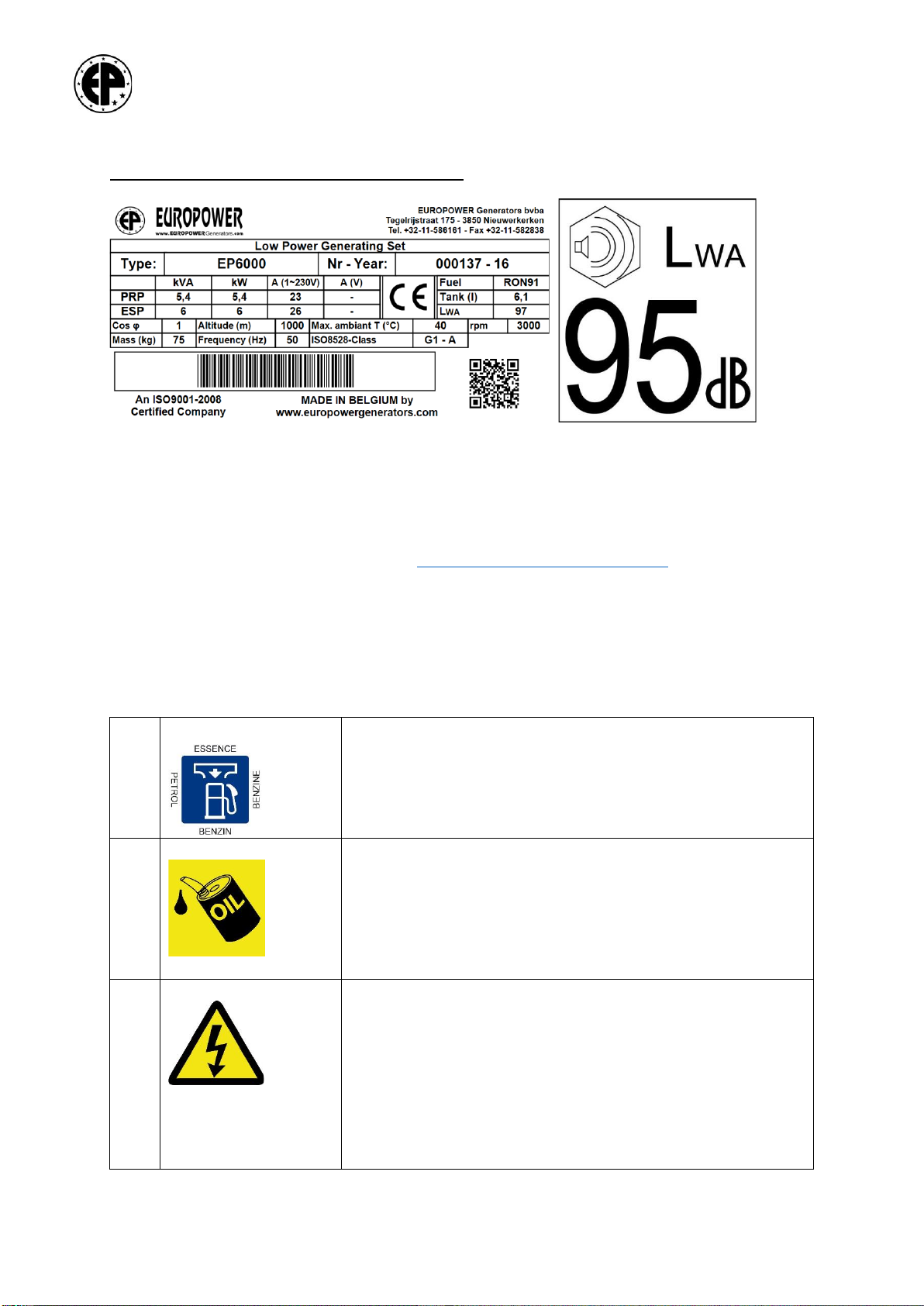
2. CE-MARK, NOISE LABEL AND PICTOGRAMS
2.1. CE-marking and noise label:
These are examples of a EUROPOWER type indication plate and a noise label.
The type indication plate can be found on every generator. The noise label
only appears on generators that comply with the European standard
2000/14/EC. More information on this can be found in the EUROPOWER
documentation or on our web site www.europowergenerators.com.
2.2. Pictograms:
Some of these pictograms are typical for a certain option or special type
of generating set. Therefore, not all pictograms necessarily appear on the
standard generating set.
EP_B
(1)
-
Here you can fill the tank with fuel. Remove the fuel filler cap and
check the fuel level. Refuel carefully to avoid fuel spillage. Do not
fill the tank to the top. You might have to lower the fuel level,
depending on operating conditions. After refuelling, reinstall the
fuel filler cap and tighten it securely. Spilled fuel causes
environmental damage. Wipe up spilled gasoline at once.
(4)
-
Here you can fill the oil by loosening the oil filler cap or dipstick.
Fill carefully to avoid oil spillage. Spilled oil should be wiped up
immediately in a correct and environmentally friendly way.
Respect the local regulations. Do not pour oil into the ground or
down the drain.
(11)
-
WARNING! –Electric shock hazard.
www.EUROPOWERgenerators.com
EP10000E-EP12000TE-IP54-EP13500TE-EP12000E-EP16000TE-
EP14000E-EP18000TE
Pg. 5 / 13
Doc.nr.:0004598
Opsteller: MH Revisie:02 Revisor: BL
Opsteldatum: 15/04/2020 Goedkeurder: GD Revisiedatum: 28/06/2021
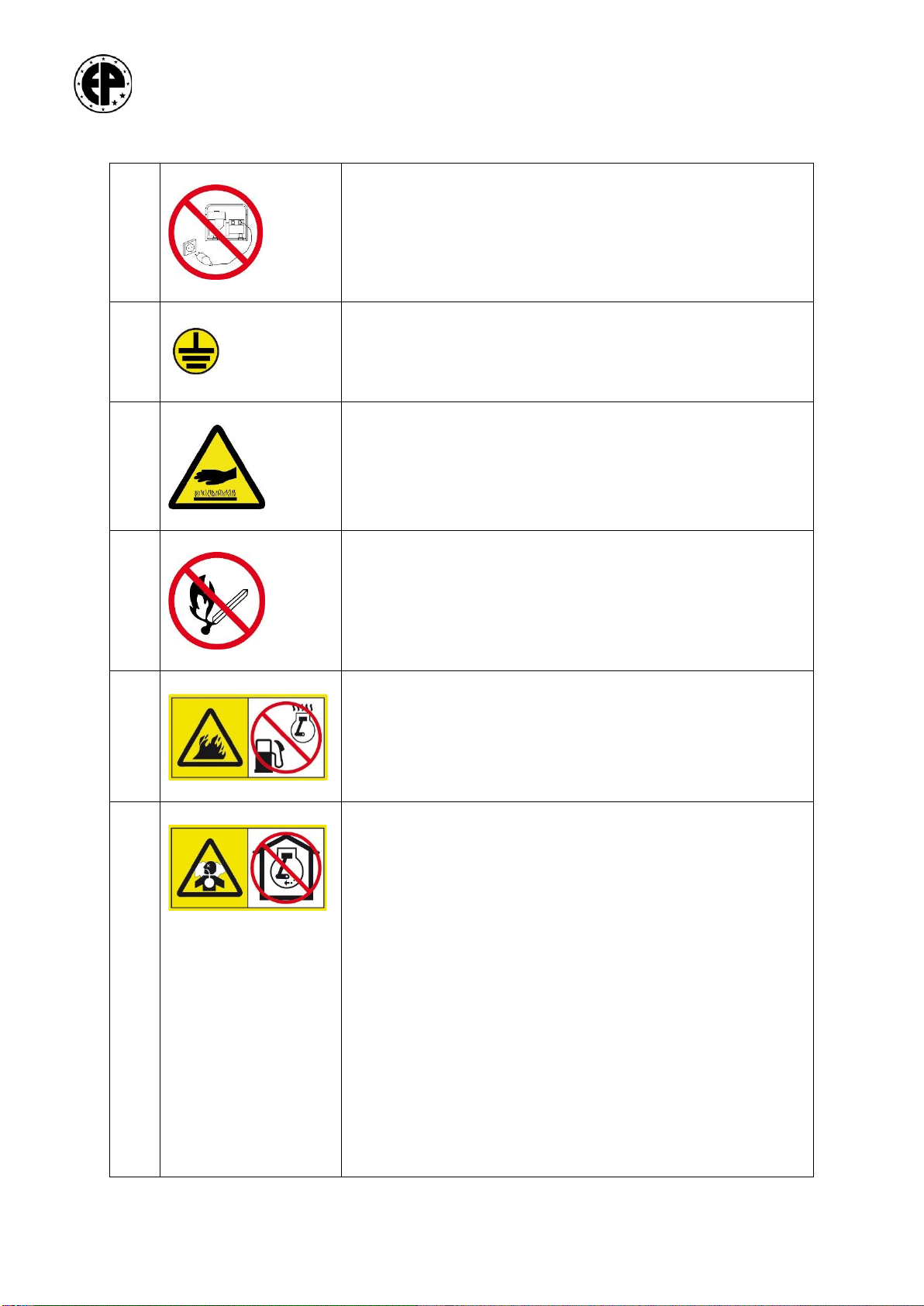
(12)
-
Never connect the generator to an installation which is also
connected to a public mains. Improper connections can allow
electrical current from the generator to back feed into the utility
lines.
Such back feed may electrocute utility company workers, and
when utility power is restored, the generator may explode, burn or
cause fires in the building’s electrical systems.
(13)
-
Here an earth pin can be connected. Follow the instructions in
this manual concerning the use of an earth pin.
(22)
-
WARNING! –Hot surface. Can cause burns. Hot engine and hot
exhaust system can cause serious and even lethal injuries. Never
work on the generating set before it has sufficiently cooled down.
(23)
-
Do not smoke nor allow sparks or flames near the generating set,
the fuel pipe, the fuel filter, the fuel pump or other possible
sources of spilled fuel or fuel vapours.
(24)
-
Fuel is highly flammable and explosive and you can be burnt or
seriously injured when refuelling. Turn the engine off and let it cool
down before refuelling.
(25)
-
The engine‘s exhaust gases contain poisonous carbon monoxide.
You can be killed or seriously hurt. Do not run the engine in a
closed environment. The exhaust system should be leak-tight and
it should be inspected regularly.

www.EUROPOWERgenerators.com
EP10000E-EP12000TE-IP54-EP13500TE-EP12000E-EP16000TE-
EP14000E-EP18000TE
Pg. 6 / 13
Doc.nr.:0004598
Opsteller: MH Revisie:02 Revisor: BL
Opsteldatum: 15/04/2020 Goedkeurder: GD Revisiedatum: 28/06/2021
(27)
-
Only use a hoist according to local safety regulations.
Never allow sharp bends in lifting cables and chains.
It is strictly forbidden to dwell or stay in the risk zone under a lifted
load. Never lift the unit over people or residential areas. Never
leave a load hanging on a hoist. Lifting acceleration and
retardation shall be kept within safe limits.
To lift heavy parts, a hoist of ample capacity, tested and approved
according to local safety regulations, shall be used.
Lifting hooks, eyes, shackles, etc. shall never be bent and shall
only have stress in line with their design load axis.
The capacity of a lifting device diminishes when the lifting force is
applied at an angle to its load axis.
For maximum safety and efficiency of the lifting apparatus all
lifting members shall be applied as near to perpendicular as
possible.
A hoist has to be installed in such a way that the object will be
lifted perpendicular.
If that is not possible, the necessary precautions must be taken to
prevent load-swinging, e.g. by using two hoists, each at
approximately the same angle not exceeding 30° from the vertical.
(28)
-
WARNING! –Consult the instruction and maintenance manual of
the engine and the alternator before carrying out maintenance.
Improper maintenance, or failure to correct a problem before
operation, can cause a malfunction in which you can be seriously
hurt or killed.
Always follow the inspection and maintenance recommendations
and schedules mentioned in the instruction and maintenance
manual of the engine and the alternator.
3. SHORT DESCRIPTION OF THE GENERATING SET
Type: EP10000E H/MA: 10 kVA max. / 9 kVA cont. –39 A 1x230 V
Type: EP13500TE H/S: 13.5 kVA max. / 12 kVA cont. –20 A 1x230 V / 14 A
3x400 V
Type: EP12000TE-IP54 H/So: 12.5kVA max. / 11kVA cont. - 17A 1x230V / 13A
3x400V
Type: EP12000TE-IP54 H/GTS: 12.5kVA max. / 11kVA cont. - 23A 1x230V / 13A
3x400V
Type: EP12000E H/S: 12 kVA max. / 10.8 kVA cont. –47 A 1x230 V
Type: EP16000TE H/S: 16 kVA max. / 14.4 kVA cont. –23 A 1x230 V / 16 A
3x400 V
Type: EP14000E H/S: 13.5 kVA max. / 12 kVA cont.–52A 1x230V
Type: EP18000TE H/S: 17.5 kVA max. / 16 kVA cont.–23A 1x230V / 18A
3x400V
Weight:

www.EUROPOWERgenerators.com
EP10000E-EP12000TE-IP54-EP13500TE-EP12000E-EP16000TE-
EP14000E-EP18000TE
Pg. 7 / 13
Doc.nr.:0004598
Opsteller: MH Revisie:02 Revisor: BL
Opsteldatum: 15/04/2020 Goedkeurder: GD Revisiedatum: 28/06/2021
- EP10000E H/MA: 146 kg, EP12000TE-IP54: 148 kg, EP13500TE H/S: 149 kg
- EP12000E H/S: 150 kg, EP16000TE H/S: 155 kg
- EP14000E H/S: 162 kg, EP18000TE H/S: 165 kg
All TYPES:
Frequency: 50 Hz
Engine:
- EP10000E-EP12000TE-IP54-EP13500TE:
HONDA GX630, 2 cylinder, 688 cm³, 3000 rpm, air-cooled
- EP12000E-EP16000TE:
HONDA GX690, 2 cylinder, 688 cm³, 3000 rpm, air-cooled
-EP14000E-EP18000TE:
HONDA iGX800, 2 cylinder, 779 cm³, 3000 rpm, air-cooled, injection
Fuel tank: 20 litres
Dimensions: L = 102cm (83cm without tank), W = 55cm, H = 60cm
Noise level:
EP10000E/EP13500TE/EP12000TE/EP12000E/EP16000TE: LwA100
EP14000E/EP18000TE: LwA 101
This generating set does not comply with the European Noise Directive
2000/14/EG: see also “Mounting instructions” to be found with “Declaration
of Incorporation according to 2006/42/EG”.
The main components of the generating set are: GX630/GX690/iGX800 air-
cooled gasoline engine (3000rpm) with starting control panel, the
alternator, the alternator control panel, the fuel tank and the frame.
For engine and alternator specifications we refer to the engine and
alternator manual supplied with each generating set.
Specifications for the control panel can be found in chapter 4.
4. DESCRIPTION OF THE CONTROL PANEL
The engine control panel contains:
-Starting key
-Hour counter
-Low oil level LED
(For EP14000E and EP18000TE, the LED functions also as an Error
Indication, see also the engine manual for more information)
-Choke knob (not for EP14000E and EP18000TE)
-Fuse(s):
oOnly for EP10000E/EP13500TE/EP12000TE/EP12000E/EP16000TE:
▪30A fuse (12V circuit protection - inside the engine
control panel)
oOnly for EP14000E and EP18000TE (the fuses are on the side of
the engine, next to the oil dipstick)
▪30A fuse (load current)
▪15A fuse (main)
-Throttle lever (only for EP10000E, EP12000TE-IP54 and EP13500TE)
The alternator control panel contains:
-Thermal-magnetic breaker
-2 sockets
-A.I.S.-module (Automatic Idle System) (only for EP12000E, EP16000TE,
EP14000E and EP18000TE)

www.EUROPOWERgenerators.com
EP10000E-EP12000TE-IP54-EP13500TE-EP12000E-EP16000TE-
EP14000E-EP18000TE
Pg. 8 / 13
Doc.nr.:0004598
Opsteller: MH Revisie:02 Revisor: BL
Opsteldatum: 15/04/2020 Goedkeurder: GD Revisiedatum: 28/06/2021
-Switch A.I.S. OFF / ON (only for EP12000E, EP16000TE, EP14000E and
EP18000TE).
5. USE OF THE GENERATING SET
-Operating points: 2 sockets with thermal-magnetic protection, A.I.S.
switch (only for EP12000E, EP16000TE, EP14000E and EP18000TE),
starting key, choke knob and throttle lever (only for EP10000E,
EP12000TE-IP54 and EP13500TE).
5.1. Starting the engine:
-check the oil level
-check the fuel level
-open the fuel cock
OPEN
-pull the choke button when the engine is cold (not for EP14000E and
EP18000TE)
-move the throttle lever to the MAX. position (only for EP10000E,
EP12000TE-IP54 and EP13500TE)
-switch A.I.S. OFF (only for EP12000E, EP16000TE, EP14000E and
EP18000TE)
-first put the starting key in the position “ON” (initiation injection
system) (only for EP14000E and EP18000TE)
-start the engine with the starting key
-close the choke slowly after a few seconds (not for EP14000E and
EP18000TE)
-let the engine warm up for a few minutes before charging
-as soon as the generating set has been started you can turn on the
A.I.S. system (= switch in the ON position, only for EP12000E,
EP16000TE, EP14000E and EP18000TE)
-connect the users.
5.2. Charging the generating set:
-on the type indication plate of the generating set you can find the
maximum charging current of the generating set
-in case of overcharge, the thermal-magnetic protection in the control
panel will switch off after some time. Check the load, reduce it if
necessary and switch on the thermal-magnetic protection again
-in case of short-circuit, the thermal-magnetic protection will switch
off immediately! First check the cause of the short-circuit and then
switch on the protection again.

www.EUROPOWERgenerators.com
EP10000E-EP12000TE-IP54-EP13500TE-EP12000E-EP16000TE-
EP14000E-EP18000TE
Pg. 9 / 13
Doc.nr.:0004598
Opsteller: MH Revisie:02 Revisor: BL
Opsteldatum: 15/04/2020 Goedkeurder: GD Revisiedatum: 28/06/2021
5.3. Stopping the generating set:
-let the generating set cool down at no load for a few minutes before
stopping the engine
-stop the engine with the starting key
close the fuel cock.
CLOSE
5.4. Automatic Idle System (only for EP12000E, EP16000TE, EP14000E and
EP18000TE):
-to switch on the A.I.S. system you have to turn the switch to the ON
position
-the generating set will automatically turn to a reduced speed (2300
200rpm for GX690 and 2000 rpm for iGX800) when there is no load
connected, or when the load has been removed. When a minimum load
(100 to 200W) is connected it will return to its nominal speed
(3000rpm).
Note:
-it can happen that the A.I.S. function does not react on some small
(electronic) charges. When this occurs, turn off the A.I.S. system by
turning the switch to OFF position
-“OFF DELAY” is set at 60 sec (-25% + 50%).: this means that the
engine will automatically turn to a reduced speed +/- 60 sec after
switching off the charge. This is to prevent excessive ON/OFF
switching of the engine.
-the “OFF DELAY”-regulator is sealed. It is forbidden to change this
setting.
5.5. Cooling
-make sure that there are no obstructions at the fresh air intake
grid, which provides cooling air for the engine and the
alternator.
-make sure that the hot cooling air from the engine and the
alternator, as well as the exhaust gasses, can easily be abducted.
-never let the generator run in an inappropriately ventilated room!
(danger of CO poisoning)
5.6. Protections:
-engine: low oil level protection
-alternator: thermal-magnetic protection.
www.EUROPOWERgenerators.com
EP10000E-EP12000TE-IP54-EP13500TE-EP12000E-EP16000TE-
EP14000E-EP18000TE
Pg. 10 / 13
Doc.nr.:0004598
Opsteller: MH Revisie:02 Revisor: BL
Opsteldatum: 15/04/2020 Goedkeurder: GD Revisiedatum: 28/06/2021
5.7. Maintenance (see also chapter 10):
All maintenance points (air cleaner, oil level dipstick, oil drain
bolt, oil filler cap, oil filter, fuel filter, valves, spark plugs) are
very good accessible. For normal maintenance activities, check the
engine manual. For engine or alternator repair, consult your dealer.
5.8. Safety for the users:
The standard version of the generating sets EP10000E –EP12000TE-IP54 -
EP13500TE - EP12000E - EP16000TE - EP14000E –EP18000TE are connected
following the IU electrical scheme. This means that for connection of
charges class 1 (charges with earth) there is a maximum of 1 charge
only, and for charges class 2 (charges with double insulation, to be
recognized by the “double square” pictogram on the machine) there is no
limitation in the quantity of charges connected at the same time on the
generating set. Contact your distributor for details on the above
subject.
Still you have to respect the minimum square (mm²) and maximum length
of the cables you are using (to assure the correct switching off of the
thermal-magnetic protection in case of short-circuit).
Insulation protection or earth leakage protection are available as an
option.
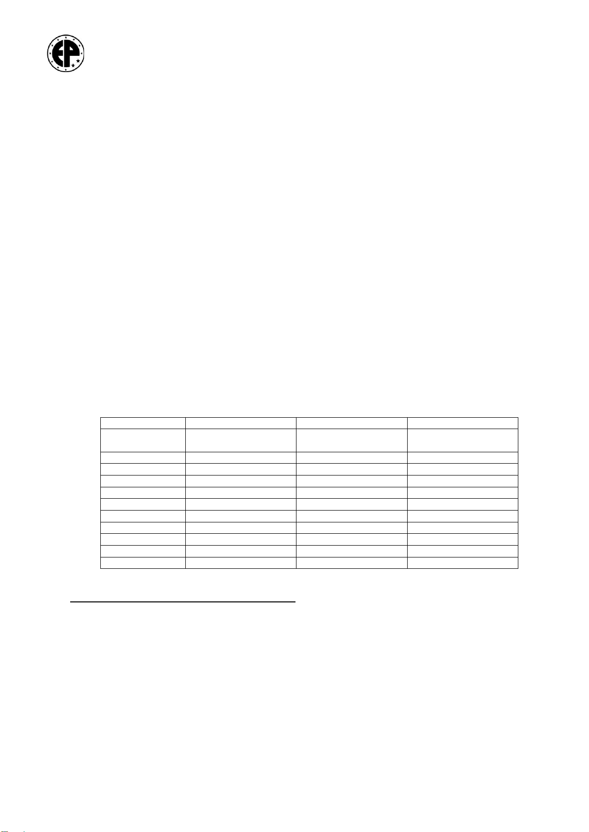
Table: of minimum cable section (in mm²) and maximum cable length (in
m) in function of the current (in A)
Cable length
Cable length
Cable length
Current in A
0 to 50 metres
> 50 to 100
metres
> 100 to 150
metres
6
1.5mm²
1.5mm²
2.5mm²
8
1.5mm²
2.5mm²
4mm²
10
2.5mm²
4mm²
6mm²
12
2.5mm²
6mm²
10mm²
16
2.5mm²
10mm²
10mm²
18
4mm²
10mm²
10mm²
24
4mm²
10mm²
16mm²
26
6mm²
16mm²
16mm²
36
6mm²
25mm²
25mm²
50
10mm²
25mm²
35mm²
6. INCORPORATION OF THE GENERATING SET
Consult your EUROPOWER dealer or EUROPOWER Generators.
See the “Mounting instructions” to be found with “Declaration of
Incorporation according to 2006/42/EG” for generating sets that do not have
the EC Declaration of Conformity IIA.

www.EUROPOWERgenerators.com
EP10000E-EP12000TE-IP54-EP13500TE-EP12000E-EP16000TE-
EP14000E-EP18000TE
Pg. 11 / 13
Doc.nr.:0004598
Opsteller: MH Revisie:02 Revisor: BL
Opsteldatum: 15/04/2020 Goedkeurder: GD Revisiedatum: 28/06/2021
7. PARTS LIST
This parts list is based on the standard versions of the EP10000E –
EP12000TE-IP54 - EP13500TE - EP12000E –EP16000TE - EP14000E –EP18000TE
generating set. For generating sets with options (e.g. insulation
protection, remote control, automatic start/stop system…) there can be
small differences! Please contact your dealer for info on parts for these
options.
Art. nr. Description
7.1. GENERATING SET
120000050 silent-bloc A 50/40 M1028 (alternator)
120001043 silent-bloc B 40/30 M823 (engine)
170000000 battery 12V 24 Ah
170000026 protection battery clamp (black)
199000058 support high box RI 300200120
199000090 cap for jerrycan
199000096 jerrycan 20 litres
199000098 frame for jerrycan
202000010 S20F-200/A 12kVA 230V Mecc-Alte alternator (EP10000E)
217000012 FK2MFS 12 kVA 230V Sincro alternator (EP12000E)
217000014 FK2MGS 13.5kVA 230V Sincro alternator (EP14000E)
217000113 FT2MES 13.5kVA 230/400V Sincro alternator (EP13500TE)
217000116 FT2MFS 16kVA Sincro alternator (EP16000TE)
217000118 FT2MGS 18kVA 230/400V Sincro alternator (EP18000TE)
217714139 SSG132LA2-R IP54 AVR 12kVA 230/400V SAEJ609B 3000tpm
(EP12000TE-IP54-So)
218000112 DWG 12,5/6-2EE IP54 12,5/6kVA 230/400V GTS alternator
(EP12000TE-IP54-GTS)
300000221 GX630R VEP4 3000rpm Honda engine (EP10000E–EP12000TE-IP54 –
EP13500TE)
300000251 GX690R VXE4 3000rpm Honda engine (EP12000E–EP16000TE)
300000281 iGX800 VX-E4-OH 3000rpm Honda engine (EP14000E–EP18000TE)
910000018 U-profile Alu 210mm, battery fixation
910000026 rod M6 210mm, battery fixation
910000115 frame type 6
7.2. CONTROL PANEL
175001008 metal box 300200120 mm, IP66
180000000 socket, Schuko type 16A 230V, with lateral earth pins
180000001 socket, Schuko type 16A 230V, with central earth pin
181000000 terminal 6mm² (EP12000E-EP12000TE-IP54 -EP13500TE-EP16000TE-
EP14000E-EP18000TE)
181000004 terminal 6mm², earthed (EP12000E-EP12000TE-IP54 -EP13500TE-
EP16000TE-EP14000E-EP18000TE)
181000005 terminal 10mm², earthed (EP10000E)
181001016 thermal-magn. protection 2-poles 16A, C-character (EP10000E-
EP12000E-EP14000E)
181001032 thermal-magn. protection 2-poles 32A, C-character (EP10000E-
EP12000E-EP14000E)
181001040 thermal-magn. protection 2-poles 40A, C-character (EP14000E)
181002636 2 position switch –for AIS system (EP12000E-EP16000TE-
EP14000E-EP18000TE)
181002640 normal open contact for 181002636 (EP12000E-EP16000TE-
EP14000E- EP18000TE)

www.EUROPOWERgenerators.com
EP10000E-EP12000TE-IP54-EP13500TE-EP12000E-EP16000TE-
EP14000E-EP18000TE
Pg. 12 / 13
Doc.nr.:0004598
Opsteller: MH Revisie:02 Revisor: BL
Opsteldatum: 15/04/2020 Goedkeurder: GD Revisiedatum: 28/06/2021
181003013 thermal-magn. protection 3-poles 13A, C-character
(EP12000TE-IP54 -EP13500TE)
181003016 thermal-magn. protection 3-poles 16A, C-character (EP16000TE)
181004020 thermal-magn. protection 4-poles 20A, C-character (EP18000TE)
181030332 CEE socket, blue 3 poles 32A 230V (EP10000E-EP12000E-
EP14000E)
181030516 CEE socket, red 5 poles 16A 400V (EP12000TE-IP54 -EP13500TE-
EP16000TE)
181030532 CEE socket 5 poles 32A 400V (EP18000TE)
390401051 ecologizer unit (A.I.S) (EP12000E–EP16000TE-EP14000E-
EP18000TE)
7.3. MAINTENANCE PARTS
217990050 diode + varistor + condensator (EP12000E)
217990074 brushes with holder FT (with 1 diode bridge)
390700056 brushes with holder FT (with 2 diode bridges)
398000630 air cleaner element GX630/GX690/iGX800
398200630 oil filter GX630/GX690/iGX800
399000030 condensator 30µF (EP12000E)
399000035 condensator 35µF (EP12000E)
A00002000 spark plug GX630/GX690
A00002001 gasoline filter 20µm GX630/GX690
A00002014 valve cover seal GX630/GX690/iGX800
A00002200 spark plug iGX800
A00002201 gasoline filter 10µm iGX800
-brushes DWG12.5/6-2EE (EP12000TE-IP54)
390400012 diode D2/125 25A (EP10000E)
-varistor (EP10000E)
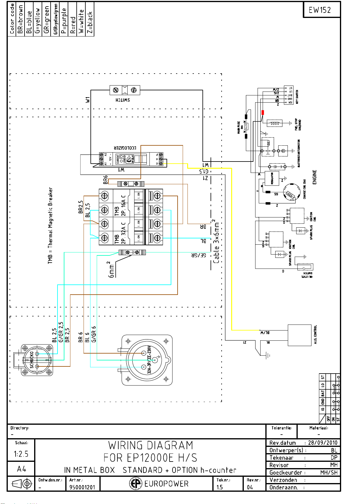
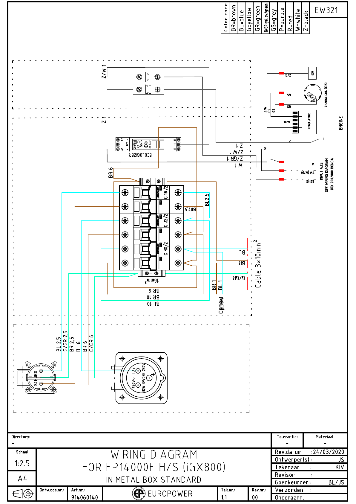
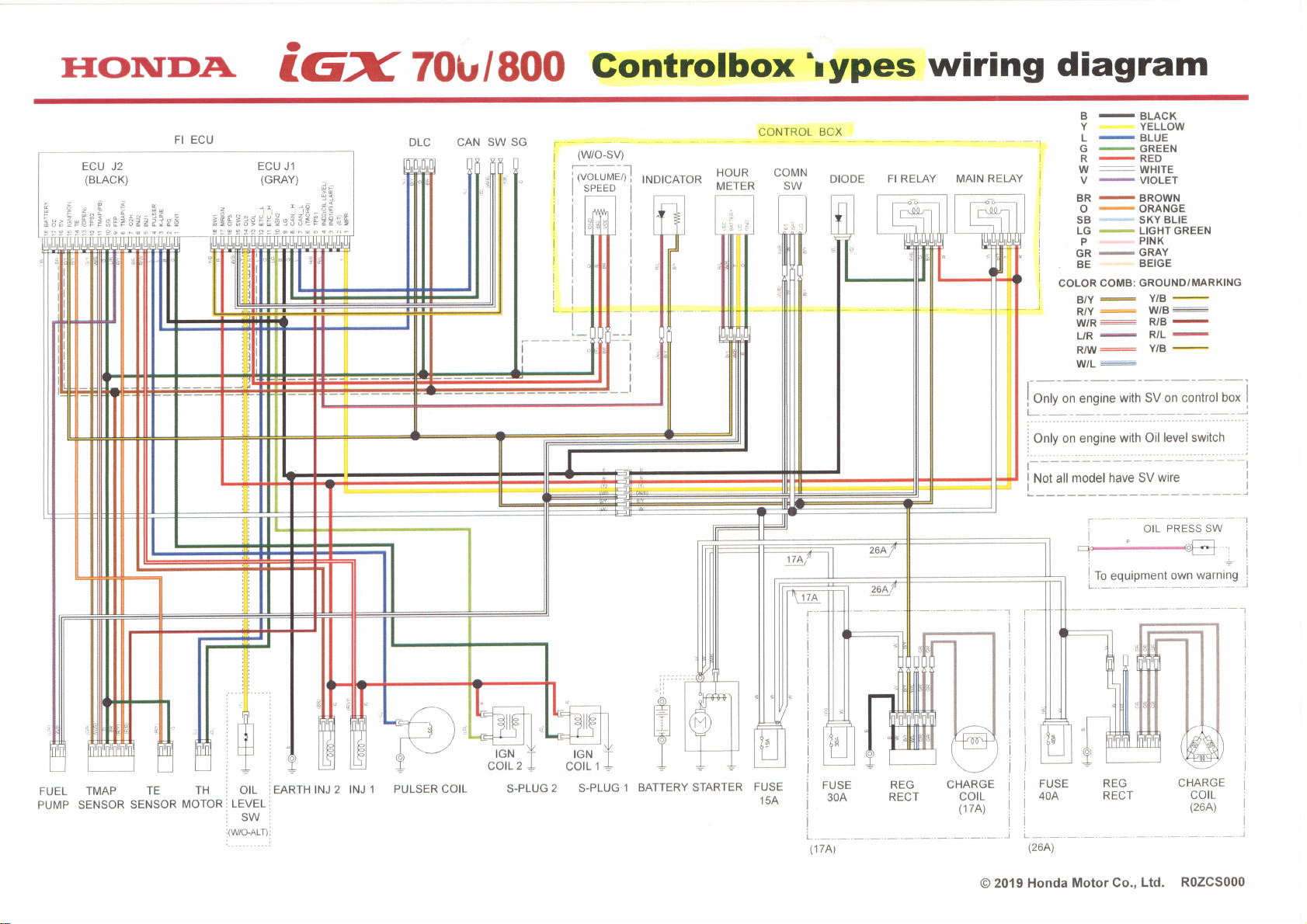
8. ELECTRICAL SCHEMES
See the electrical schemes in the engine and alternator manual and the
enclosed EUROPOWER electrical schemes.
9. BUILDING-IN DIMENSIONS
To be asked at your EUROPOWER dealer.
10. MAINTENANCE
10.1. Alternator:
Alternator: besides regular visual control of the different alternator
parts, the alternator only needs a check of the rotor bearing on every
general engine maintenance.
For the alternators with brushes (EP12000TE-IP54 -EP13500TE-EP16000TE-
EP18000TE): the brushes should be checked at every general engine
maintenance. The expected lifetime of the brushes is 2500 to 3000 hours.

www.EUROPOWERgenerators.com
EP10000E-EP12000TE-IP54-EP13500TE-EP12000E-EP16000TE-
EP14000E-EP18000TE
Pg. 13 / 13
Doc.nr.:0004598
Opsteller: MH Revisie:02 Revisor: BL
Opsteldatum: 15/04/2020 Goedkeurder: GD Revisiedatum: 28/06/2021
10.2. Engine:
See engine manual for maintenance intervals.
Remark: in the factory, the engine has been filled with 15W40 oil (for
temperatures up to -10°C). The minimum specification of this oil has to be
API SJ/CF-4.
If the ambient temperature is lower, 10W30 oil (up to -15°C) or full
synthetic 5W30 oil (up to -25°C) should be used. Here the minimum
specification also has to be API SJ/CF-4.
11. TRANSPORT AND STORAGE
To prevent fuel spillage when transporting or during temporary storage, the
generator should be secured upright in its normal operating position, with
the engine switch in position “OFF”.
When transporting the generators:
•Close the fuel cock
•Do not overfill the tank (there may not be any fuel in the filler
neck).
•Do not use the generator while it is placed in a vehicle.
•Take the generator off the vehicle and use it in a well-ventilated
place.
•When placing the generator in a vehicle, avoid a place exposed to
direct sunlight. When the generator is left in an enclosed vehicle
for a longer period of time, high temperature inside the vehicle
could cause fuel to vaporise resulting in a possible explosion.
•Do not drive on a rough road for an extended period with the
generator on board. If you must transport the generator on a rough
road, drain the fuel from the generator beforehand.
Before storing the unit for an extended period ( > 2 months):
•Make sure the storage area is free of excessive humidity and dust.
•For gasoline generating sets: drain the fuel.
•Turn the fuel cock “ON” (if present), loosen the carburettor drain
screw and drain the gasoline from the carburettor into a suitable
container.
•Turn the fuel cock “OFF” (if present) and tighten the carburettor
drain screw securely.
•WARNING
Gasoline is extremely flammable and explosive under certain
conditions.
Do not smoke or allow flames or sparks in the area.
•Remove the spark plugs and pour about a tablespoon of clean engine
oil into the cylinders. Crank the engine several revolutions to
distribute the oil, then reinstall the spark plugs.
•Reinstall the spark plug caps on the spark plugs securely.
•Refresh the engine oil.
•Remove the battery and connect it to a battery charger. This way you
will increase the life span of the battery.


I1IONTfDA O
lGX 70lr/800 Gontrolbox'rypes wiring diagram
CONTROL BCX -
BLACK
YELLOW
_ BLUE
FI ECU DLC CAN SW SG I
I
!
L
i
I
I
I
t
(wo-sv) DIODE FI RELAY MAIN RELAY
GREEN
RED
WHITE
VIOLET
BROWN
ORANGE
SKY BLIE
LIGHT GREEN
PINK
GRAY
BEIGE
GROUND/MARKING
-l
I
I
I
l
I
I
I
B
L
G
R
w
BR
r. -
ECU J2
(BLACK) ECU J1
(GRAY) HOUR
METER COMN
SW
i.F:
i,'!,El!,'li*;,;lro tiri=tittr:.,io9 ,{,
lii r
??'!2
INDICATOR
IGN
colL 1
S-PLUG 1 BATTERY STARTER FUSE
'l54
o-
SB
LG-_.
P
GR-
.BE
COLOR COMB:
RA r:
w/L:
REG
RECT
R/B
-
Y/B
-
I
I
I
I
I
I
-I Only on engine with SV on control box
Only on engine with Oil level switch
I Not all model have SV wire
OIL PRESS SW
To equipment own warning
17A
!
i
f
IGN
colL 2
l
I
l
I
I
I
L
l
I
i
i
I
l
I
FUSE
30A REG
RECT CHARGE
colL
(17A)
FUSE
404 CHARGE
corL
(26A)
FUEL TMAP TE TH I OIL TEARTH INJ 2 INJ 1 PULSER COIL
PUMP SENSOR SENSOR MOTOR i LEVEL
iSW
,tWO-lrfir iL (26A)
O 2019 Honda Motor Co., Ltd. R0ZCS000
S.PLUG 2
(17A)
This manual suits for next models
7
Table of contents
Other EuroPower Portable Generator manuals

Popular Portable Generator manuals by other brands

Sincro
Sincro EP Series Use and maintenance manual

Impax
Impax IM1500I instruction manual

King Canada
King Canada PowerForce KCG-1501GX instruction manual

SEFRAM
SEFRAM 4410B quick start guide

Steelcase
Steelcase Answer Modular Power manual

Generac Portable Products
Generac Portable Products RS5500 owner's manual


