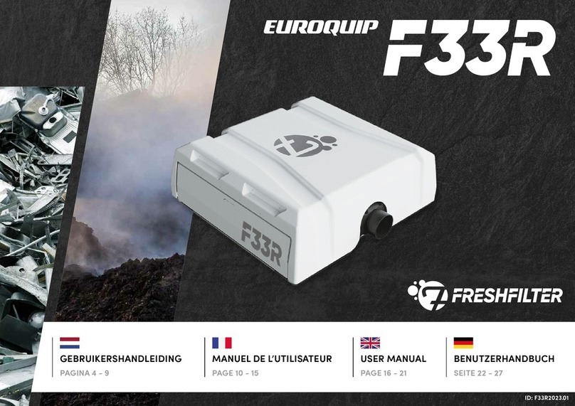
Euroquip FRESHFILTER F20 User manual

BENUTZERHANDBUCH
SEITE 22 - 27
USER MANUAL
PAGE 16 - 21
MANUEL DE L’UTILISATEUR
PAGE 10 - 15
GEBRUIKERSHANDLEIDING
PAGINA 4 - 9
ID: F202023.01

EC TYPE DECLARATION OF CONFORMITY || CE - DÉCLARATION DE CONFORMITÉ || EG-TYPENKONFORMITÄTSERKLÄRUNG
-ID
2
We FRESHFILTER GROUP INTERNATIONAL HEADQUARTERS RUISVOORN 2
Nous SIÈGE INTERNATIONAL 4941 SB RAAMSDONKSVEER
Wir HAUPTQUARTIER NETHERLANDS (LES PAYS-BAS)
declare under our sole responsibility that the product (cab air filtration system):
déclarons sous notre seule responsabilité que le/les produit (système de pressurisation et filtration):
erklären in alleiniger Verantwortung, dass das Produkt (Schutzbelüftung):
declare under our sole responsibility that the product (controller):
déclarons sous notre seule responsabilité que le/les produit (achage en cabine par contrôleur) :
erklären in alleiniger Verantwortung, dass das/die Produkt(e) (Signalisierung):
This Declaration of conformity is suitable to the Euro-
pean Standard EN45014 General Criteria for supplier’s
Declaration of Conformity. The basis for the criteria has
been found in international documentation particularly
in ISO/IEC, Guide 22, 1982, Information for manufacturer’s Declaration of
Conformity with standards or other technical specifications.
Cette déclaration de conformité est conforme à la norme européenne
EN45014 Critères généraux pour la déclaration de conformité du fournis-
seur. La base des critères a été trouvée dans la documentation internati-
onale, en particulier dans ISO/IEC, Guide 22, 1982, Informations pour la
déclaration de conformité du fabricant aux normes ou autres spécificati-
ons techniques.
Diese Konformitätserklärung entspricht der Europäischen Norm EN45014
Allgemeine Kriterien für die Konformitätserklärung von Lieferanten. Die
Grundlage für die Kriterien findet sich in internationaler Dokumentation,
insbesondere in ISO/IEC, Guide 22, 1982, Information for Manufacturer’s
Declaration of Conformity with Standards or otherTechnical Specifications.

Scan de QR-code voor uw machinegegevens, het
geldende keuringscertificaat en digitaal filterlogboek.
Scannez le code QR pour les données de votre machine,
le certificat d’inspection applicable et le journal de filtre
numérique.
Scan the QR code for your machine data, the applicable
inspection certificate and and digital filter log.
Scannen Sie den QR-Code für Ihre Maschinendaten,
das gültige Abnahmeprüfzeugnis und das digitale
Filterprotokoll.
MACHINE
QR
3
We FRESHFILTER GROUP INTERNATIONAL HEADQUARTERS RUISVOORN 2
Nous SIÈGE INTERNATIONAL 4941 SB RAAMSDONKSVEER
Wir HAUPTQUARTIER NETHERLANDS (LES PAYS-BAS)
declare under our sole responsibility that the product (cab air filtration system):
déclarons sous notre seule responsabilité que le/les produit (système de pressurisation et filtration):
erklären in alleiniger Verantwortung, dass das Produkt (Schutzbelüftung):
Raamsdonksveer
01-01-2021 G. Mols
declare under our sole responsibility that the product (optional: recirculation system):
déclarons sous notre seule responsabilité que le/les produit (système de recirculation en option):
erklären in alleiniger Verantwortung, dass das/die Produkt(e) (optionalem Umluftsystem):
to which this declaration relates is/are in conformity with European Harmonises Standards as publised in:
au(x)quel(s) se réfèrent cette déclaration, est/sont conforme(s) aux normes européennes harmonisées telles que publiées dans :
auf die sich diese Erklärung bezieht, mit den harmonisierten europäischen Normen übereinstimmt, wie veröentlicht in:
the conformity was checked in accordance with the following harmonised EN standard(s):
la conformité fût contrôlée selon la/les norme(s) EN-harmonisées :
die Konformität wurde nach folgenden harmonisierten EN-Normen geprüft):
the conformity was checked in accordance the provisions of the directives (if applicable):
la conformité a été vérifiée conformément aux dispositions des directives (le cas échéant) :
die Konformität wurde gemäß den Bestimmungen der Richtlinien geprüft (falls zutreend):

INHOUDSOPGAVE
SYSTEEM INFORMATIE
5TECHNISCHE SPECIFICATIES VAN DE F20
5PLAATSINGSCRITERIA OP MACHINES
FILTERINFORMATIE
6FILTERWIJZER
7INSTRUCTIE FILTERPLAATSING F20
7BESTELNUMMER FILTERS F20
BESTURING CONTROLLER
8BESTURING VAN DE CONTROLLER
8MOGELIJKE ALARMERINGEN VAN DE CONTROLLER
ONDERHOUD
9INSPECTIE VAN DE F20
FILTERLOGBOEK
28 MEERTALIG FILTERLOGBOEK
4
VOORWOORD
De gebruikershandleiding is bedoeld als leidraad voor
een veilig en correct gebruik en onderhoud van het
overdrukfiltersysteem. Lees de gebruikershandleiding
alvorens het eerste gebruik van het overdrukfiltersys-
teem goed door.
Bewaar de gebruikershandleiding te allen tijde in de
cabine van de machine. Zo kan de operator gemakke-
lijk de handleiding raadplegen.
Het is van belang dat de gebruikershandleiding altijd
bij het overdrukfiltersysteem geleverd wordt. Bij ver-
lies, beschadiging of onleesbaarheid dient de hand-
leiding direct vervangen te worden. De handleiding is
te bestellen met het ID-nummer op de voorpagina.

SYSTEEM INFORMATIE
TECHNISCHE SPECIFICATIES & PLAATSINGSCRITERIA F20
Het F20 overdrukfiltersysteem bestaat uit de volgende componenten en specificaties:
5
Bij het monteren van de F20 op uw machine is het van belang dat het overdrukfiltersysteem geen belemmering
vormt voor de normale werkzaamheden. Bij een plaatsing op het dak van een cabine moet één zijde van de ma-
chine veilig toegankelijk zijn om veilig service te verlenen. Tevens dient er rekening gehouden te worden met de
volgende plaatsingseisen:
De inlaatopening van de overdrukfilterinstallatie is zodanig geplaatst dat het aanzuigen van
uitlaatgassen wordt vermeden.
De uitblaasopening van de overdrukfilterinstallatie in de cabine is zodanig geplaatst dat deze
niet leidt tot een hinderlijke luchtstroom.
De bewakingsapparatuur is zodanig geïnstalleerd dat de door de apparatuur afgegeven
waarde op de werkplek kan worden waargenomen.
Het klimaatbeheersingssysteem kan alleen maar lucht aanzuigen via de overdrukfilterinstallatie.
Indien met directe doorvoer gemonteerd beschikt het systeem over een recirculatiestand.
1
2
3
4
420 mm
Ø350 mm Leeggewicht 13 kg
Materiaal RVS304
Stolters P1 en P3
Koolfilters 10 kg actiefkool (i.c.m. een hoge kap)
Geluidsniveau < 60 db
Normering NEN4444 / CROW400 / ISO23875
Sterknop met
toebehoren
F20 standaard kap
F20 Standaard
P1/P3 combinatiefilter
Filtersensoren
Artikelnummer F20
kabelboom
systeemdeel
Blower
Bodemplaat t.b.v.
blowercompartiment.

FILTERINFORMATIE
INFORMATIE OVER ALLE TYPE OVERDRUKFILTERS
Het plaatsen van de juiste filters op de juiste manier is van groot belang. De aard van de vervuiling
bepaalt het type van de te plaatsen filters. Dit wordt veelal bepaald door een veiligheidsdeskundige.
6
P1/P3 COMBINATIE STOFFILTER
Bij een configuratie zonder actiefkoolfilter kan er een standaard P1/P3 com-
binatiefilter worden geplaatst. Dit combinatiefilter filtert schadelijke (fijn)
stof zoals asbest en kwartsstof (filtering van 0,3 m met een eciency van
99,95%). Het P1 filter zorgt voor bescherming van het P3 deel. Het filter wordt
conform EN1822 geproduceerd, getest op lekdichtheid en geleverd met test
certificaat.
Norm: EN1822
Filterklasse: H13
Functie: Afvangen van (giftig) fijnstof
Wisselen: 6 maanden of zichtbaar sterke verontreiniging.
In een configuratie met een actief koolfilter wordt het standaard combinatie-
filter P1/P3 vervangen door een smal combinatiefilter P1/P3. Dit filter heeft de-
zelfde functionaliteit als het standaard filter, maar zorgt ervoor dat er een 3,5
kg actief koolfilter op de binnenzijde van het stolter geschoven kan worden.
In Nederland geldt een andere norm, waarbij een actiefkoolstolter mini-
maal 10 kg actief kool moet bevatten. Filters met deze hoge capaciteit zijn
ook te plaatsen door de lage kap te vervangen voor een hoge kap. Hier leest
u meer over in de plaatsingsinstructie op pagina 7.
ACTIEFKOOLFILTERS
Bij bijvoorbeeld bodemsaneringen komen vaak schadelijke gassen en dampen vrij,
welke op een langer termijn kunnen zorgen voor ernstige schade aan uw gezondheid.
De actieve kooldeeltjes (koolstofatomen) oefenen een aantrekkingskracht uit op gas-
vormige of vloeibare deeltjes (moleculen).
Norm: EN12941 / EN14387
Functie: Afvangen van giftige of aangename dampen/geuren.
Wisselen: 13 weken (540 uur), doorslag of na iedere sanering.
Het te plaatsen type koolfilter hangt af van de vervuiling. De norm EN12941/EN14387
zorgt voor een duidelijke indeling voor verschillende chemische substanties en hun ad/
chemsorptie eis:
A Aromatische koolwaterstoen; kookpunt >65°C (benzine, olie, mineralen)
B An-organische verbindingen (chloor, blauwgaszuur, cyanide)
E Zure gassen (zoutzuur, zwaveldioxide, mierenzuur)
K Aminen (ammoniak, ammoniakverbindingen, aniline)
X Aromatische koolwaterstoen; kookpunt > 65°C (aceton, chloroform)
HG Organische kwikverbindingen (kwik, methylkwik, merbromide)
Actiefkoolfilters kunnen meerdere chemische substanties bevatten, zoals ABEK.

FILTERPLAATSING
INSTRUCTIES FILTERPLAATSING F20
Let op! Gebruik bij openen de juiste persoonlijke beschermingsmiddelen. De vervuilde filters
moeten conform de regels van de wet milieubeheer worden afgevoerd.
7
BESTELNUMMERS F20 LAGE CONFIGURATIE
VX203011EU513 F20 P1/P3 Stolter (standaard)
VX203024EU513 F20 P1/P3 Stolter (smal)
KX202411A F20 3,5 kg Actiefkoolstolter type A
KX202411AB F20 3,5 kg Actiefkoolstolter type AB
KX202411AHg F20 3,5 kg Actiefkoolstolter type AHg
KX202411ABEK F20 3,5 kg Actiefkoolstolter type ABEK
KX202411ABEKHg F20 3,5 kg Actiefkoolstolter type
ABEKHg
KX202411AK F20 3,5 kg Actiefkoolstolter type AK
KX202411AX F20 3,5 kg Actiefkoolstolter type AX
BESTELNUMMERS F20 HOGE CONFIGURATIE
VX613024EU513 F20 P1/P3 Stolter (hoog)
KX612411A F20 10 kg Actiefkoolstolter type A
KX612411AB F20 10 kg Actiefkoolstolter type AB
KX612411AHg F20 10 kg Actiefkoolstolter type AHg
KX612411ABEK F20 10 kg Actiefkoolstolter type ABEK
KX612411ABEKHg F20 10 kg Actiefkoolstolter type
ABEKHg
KX612411AK F20 10 kg Actiefkoolstolter type AK
KX612411AX F20 10 kg Actiefkoolstolter type AX
INSTALLATIE VAN HET STANDAARD P1/P3 COMBINATIE STOFFILTER
Draai de sterknop los en haal de deksel volledig van de basis af.
Plaats het P1/P3 stolter (VX203011EU513) op de basis en zorg dat het filter niet blijft
steken op de rand.
Plaats de deksel terug en draai de sterknop stevig aan. Dit zorgt er namelijk voor dat het
filter op zijn plek blijft.
INSTALLATIE VAN EEN LAAG P1/P3 COMBINATIE STOFFILTER & 3,5 KG KOOL (NIET VOLGENS NEN4444 / CROW400)
Draai de sterknop los en haal de deksel volledig van de basis af.
Plaats het P1/P3 Stolter (VX203024EU513) op de basis en zorg dat het filter niet blijft
steken op de rand. Schuif vervolgens het 3,5 kg actiefkoolfilter (KX202411**) in het P1/P3
combinatiefilter.
Plaats de hoge deksel terug en draai de sterknop stevig aan. Dit zorgt er namelijk voor
dat het filter op zijn plek blijft.
INSTALLATIE VAN EEN HOOG P1/P3 COMBINATIE STOFFILTER & 10 KG KOOL
Draai de sterknop los en haal de deksel volledig van de basis af. Verleng het draadeind
met het uitbereidingsdeel zoals afgebeeld.
Plaats het hoge P1 P3 stolter (VX613024EU513)op de basis en zorg dat het filter niet
blijft steken op de rand. Schuif vervolgens het 10 kg actiefkoolfilter (KX612411**) in
het P1/P3 combinatiefilter.
Plaats de hoge deksel terug en draai de sterknop stevig aan. Dit zorgt er namelijk voor
dat het filter op zijn plek blijft.
1
2
3
1
2
3
1
2
3

CONTROLLER
BEDIENING & ALARMERINGEN
De controller bevind zich in de cabine en stuurt het overdruksysteem automatisch aan. Zodra
de cabine is afgesloten dient het systeem in automatische stand te staan.
BEDIENING VAN DE CONTROLLER
Als de controller in automatische modus staat, wordt de druk automatisch
gereguleerd. Het is dan ook aan te raden om de bediening altijd in deze
modus te gebruiken. Het bedienen van de controller kan met de volgende
vier buttons:
Er zijn drie modi in te stellen door op de rode button te drukken,
namelijk: automatisch, handmatig of stand-by. De controller start
in de automatische modus op.
Met de groene button kunt u de weergegeven informatie op het
scherm aanpassen. Het scherm zal altijd opstarten met de weergave
van de overdruk in de cabine. Verder worden de urenstand en
luchtkwaliteit (indien sensor is aangesloten) weergegeven.
Met de gele en blauwe button kunt u het motorvermogen van het
overdruksysteem reguleren (weergave is procentueel). Dit is enkel
mogelijk als de modus op handmatig staat.
Het overdruksysteem kan volledig uitgezet worden, dit doet u door de rode
button gedurende 3 seconden vast te houden. Om het systeem terug aan te
zetten herhaalt u deze handeling.
ALARMERINGEN VAN DE CONTROLLER
Naast het automatisch reguleren van de druk waarschuwt de controller bij potentieel
gevaar. Dat doet de controller als volgt:
Geen filters aanwezig
Er zijn geen overdrukfilters geïnstalleerd, hierdoor zal het overdruksysteem niet in
werking treden.
Overdruk > 300 Pa.
De opgebouwde druk is te hoog. Zet de controller in automatische modus of verlaag
het motorvermogen met de blauwe knop.
Overdruk < 100 Pa.
De opgebouwde druk is te laag. Controleer of alle deuren en ramen goed gesloten zijn.
Luchtstroom te hoog
De cabine komt wel op de juiste druk, maar door een lek ergens in de afgesloten
ruimte moet er zoveel lucht de cabine ingevoerd worden, dat de passerende lucht te
snel door de filters gaat. Hierdoor zal de controller in veiligheidsmodus gaan.
Air quality low
De gasconcentratie in de cabine is te hoog. Dit kan duiden op het ontbreken van een
actiefkoolfilter, het verkeerde actiefkoolfilter of de verzadiging hiervan.
Error, contact your dealer
Er is een techisch defect in het overdrukfiltersysteem. Neem contact op met uw dealer.
8

ONDERHOUD
INSPECTIE VAN UW OVERDRUKFILTERSYSTEEM
Het is van belang dat het overdrukfiltersysteem in conditie blijft, laat uw systeem jaarlijks
inspecteren om u of uw medewerkers veilig te laten werken.
Na aflevering van het overdrukfiltersysteem wordt er een
certificaat verstrekt. Dit certificaat heeft een geldigheid
van één jaar. Ook is het keuringssticker in de cabine zicht-
baar aanwezig. Op dit keuringssticker is de vervaldatum
van de certificering te vinden. Door de QR-code te scannen
kan men ook de certificering online inzien. Het digitale
filter logboek is ook te vinden via dezelfde code.
Na een jaar is het ten zeerste aan te raden om uw over-
drukfiltersysteem jaarlijks te laten controleren door uw
dealer. De dealer zal het overdrukfiltersysteem inspecteren
op de geldende norm in uw land. Zo blijft uw systeem in topconditie en blijft
het werken in een sterk verontreinigde omgeving veilig. De vervaldatum van de
sticker zal worden aangepast en is de vernieuwde certificering ook te vinden via
de QR-code.
Een bijkomend voordeel van de QR-code is dat service en/of filters kunnen worden
aangevraagd. Uw dealer krijgt direct een melding van uw aanvraag en kan u snel
van dienst zijn. Wilt u liever uw dealer bellen of een e-mail sturen, de gegevens zijn
ook te vinden op de achterzijde van deze handleiding.
De overdruk in de cabine is meer dan 100 Pa en minder dan 300 Pa met
een luchtopbrengst tussen de 40 en 120 m. De druk is real-time af te
lezen op de controller in de cabine.
Het overdrukfiltersysteem is zodanig ontworpen dat de aangezogen
lucht enkel via het filterpakket in de werkruimte kan komen.
Er is een groene indicatie aanwezig waaraan vanaf de werkplek kan
worden gezien of het overdrukfiltersysteem in gebruik is en filters zijn
geplaatst. Optioneel is deze groenindicatie ook buiten de cabine uit te
bereiden in de vorm van een groene lamp.
Indien een sensor voorhanden is, geeft deze een alarmering boven de
gestelde grenswaarde.
Het is mogelijk om het overdrukfiltersysteem automatisch te laten starten
bij het starten van de machine. Het is mogelijk om het systeem na het
opstarten weer uit te schakelen.
Het systeem heeft de mogelijkheid om te worden uitgebreid met een
recirculatie unit in de cabine.
Voordat een F20 overdrukfiltersysteem wordt gemonteerd op uw machine
is het
systeem produceert volgens de strengste normen ter wereld. Door de F20 te
conformeren aan de onderstaande normen is het systeem wereldwijd inzetbaar:
9
NEN4444 & CROW400
Geldig t/m:
1 2 3 4 5 6 7 8 9 10 11 12
2022 2023 2024 2025 2026

TABLE DES MATIÈRES
INFORMATIONS SUR LE SYSTÈME
11 SPÉCIFICATIONS TECHNIQUES
11 PRECONISATIONS D’INSTALLATION
FILTRES À SURPRESSION F20
12 FILTRATION
13 INSTRUCTIONS D’INSTALLATION D’UN FILTRE F20
13 RÉFÉRENCES DES FILTRES F20
AFFICHAGE EN CABINE PAR CONTROLEUR
14 DESCRIPTIF DU CONTROLEUR
14 POSSIBILITES D’ALERTES
MAINTENANCE
15 INSPECTION DU F20
JOURNAL DU FILTRE
28 JOURNAL DU FILTRE MULTILINGUE
10
AVANTPROPOS
Le manuel de l'utilisateur est destiné à fournir des
conseils sur l'utilisation et l'entretien sûrs et corrects
du système de filtre de surpression. Avant d'utiliser le
système de filtre de surpression pour la première fois,
lisez attentivement le manuel de l'utilisateur.
Conservez le manuel d'utilisation à tout moment dans
la cabine de la machine. L'opérateur peut ainsi le con-
sulter facilement.
Il est important que le manuel d'utilisation accompag-
ne toujours le système de filtre de surpression. En cas
de perte, de détérioration ou d'illisibilité, le manuel
doit être remplacé immédiatement. Le manuel peut
être commandé en utilisant le numéro d'identification
figurant sur la page de garde.

INFORMATIONS SUR LE SYSTÈME
SPÉCIFICATIONS TECHNIQUES & CRITÈRES D’INSTALLATION
Le système de filtration/surpression F20 est caractérisé par les composants standards
et les spécifications suivantes :
11
Lors du montage du F20 sur votre machine, il est important que le système de filtration/surpression n’entrave
pas les opérations normales. Lorsqu'elle est placée sur le toit d'une cabine, un côté de la machine doit être
accessible en toute sécurité pour assurer un service sûr. Il faut en outre tenir compte des exigences suivantes
en termes d’installation :
Le système de filtration/suppression est installé sur la machine de manière à éviter l'aspiration des
gaz d'échappement.
Le flux d'air généré par le système de filtration/surpression dans la cabine est placé de manière à
ne pas provoquer de courant d'air gênant pour l'opérateur.
Le contrôleur est installé de manière à que la valeur indiquée peut-êtr lue par l'opérateur de son
poste de travail.
Le système de climatisation ne peut qu'aspirer l'air qu'à travers l'installation du système de filtration/
surpression. S'il est installé avec une admission d'air directement en cabine, dans ce cas la climati-
sation fonctionnera en mode
<<
recyclage
>>
.
1
2
3
4
420 mm
Ø350 mm Poids à vide 13 kg
Matériau Inox 304
Filtre Poussière P1 et P3
Filtre Charbon 3,5 - 10 kg de charbon actif
Niveau sonore < 60 db
Certification CARSAT (ED 6228)
Molette avec accessoires
Capot standard F20
Filtre combiné P1/P3
standard F20 Capteurs
optiques du filtre
Numéro d'article F20
Faisceau de câbles
Ventilateur
Fond du compartiment
du ventilateur

INFORMATIONS SUR LES FILTRES
INFORMATIONS SUR TOUS LES TYPES DE FILTRES SOUS PRESSION
Placer les bons filtres de la bonne manière est d’une grande importance. La nature de la
pollution détermine le type de filtres à installés.
12
FILTRE A POUSSIERE P1/P3
Dans une configuration sans filtre à charbon actif, un filtre combiné standard
P1/P3 peut être installé. Ce filtre combiné filtre les poussières (fines) nocives
comme l’amiante et la poussière de quartz (filtration de 0,3 m avec une
ecacité de 99,95%). Le filtre P1 protège la partie P3. Le filtre est fabriqué
conformément à la norme EN1822, testé pour son étanchéité et fourni avec
un certificat de test.
Norme: EN1822
Classe de filtre: H13
Fonction: Capture des particules fines (toxiques).
Changement: Au maximum tous les 6 mois (1080 heures)
ou en cas de fort encrassement constaté.
Dans une configuration avec filtre à charbon actif, le filtre combiné standard
P1/P3 est remplacé par un filtre combiné étroit P1/P3. Ce filtre a la même
fonctionnalité que le filtre standard, mais garantit qu’un filtre à charbon actif
de 3,5 kg peut être glissé à l’intérieur du filtre à poussière.
Si une capacité plus élevée est requise, par exemple en raison d’une concen-
tration extrêmement élevée de fumées (toxiques), un filtre à charbon de 10
kg peut également être installé. En remplaçant le capot et les filtres par une
version supérieure, le F20 est capable de le faire.
FILTRE AU CHARBON ACTIF
Par exemple, l’assainissement des sols libère souvent des gaz et des vapeurs nocifs,
qui peuvent nuire gravement à votre santé à long terme. Les particules de charbon
actif (atomes de carbone) exercent une force d’attraction sur les particules gazeuses
ou liquides (molécules).
Norme: EN12941 / EN14387
Fonction: Capture des vapeurs et/ou odeurs toxiques et à désagréments.
Change-
ment:
Maximum 13 semaines (540 heures), après
saturation ou après chaque décontamination.
Le type de filtre à charbon à installer dépend de la contamination. La norme EN12941/
EN14387 fournit une classification claire pour diérentes substances chimiques et leur
exigence d’ad/chimsorption :
A Hydrocarbures aromatiques ; point d’ébullition >65°C (essence, huile, minéraux)
B Composés inorganiques (chlore, cyanure, cyanure)
E Gaz acides (acide chlorhydrique, dioxyde de soufre, acide formique)
K Amines (ammoniac, composés ammoniacaux, aniline)
X Hydrocarbures aromatiques ; point d’ébullition > 65°C (acétone, chloroforme)
HG Composés organiques du mercure (mercure, méthylmercure, merbromure)
Les filtres à charbon actif peuvent contenir plusieurs substances chimiques, comme
l’ABEK.

INSTRUCTIONS
D’INSTALLATION D’UN FILTRE F20 AVEC RÉFÉRENCE
Attention ! Lors de l’ouverture, utilisez le bon équipement de protection individuelle. Dans certains
cas le filtre pollué doit être transporté conformément aux directives de la Loi sur l’Environnement.
13
CODES DE COMMANDE F20 CONFIGURATION STANDARD
VX203011EU513 F20 Filtre Poussière P1/P3 combi
VX203024EU513 F20 Filtre Poussière P1/P3 combi (fin)
KX202411A F20 3,5 kg Filtre Charbon type A
KX202411AB F20 3,5 kg Filtre Charbon type AB
KX202411AHg F20 3,5 kg Filtre Charbon type AHg
KX202411ABEK F20 3,5 kg Filtre Charbon type ABEK
KX202411ABEKHg F20 3,5 kg Filtre Charbon type ABEKHg
KX202411AK F20 3,5 kg Filtre Charbon type AK
KX202411AX F20 3,5 kg Filtre Charbon type AX
CODES DE COMMANDE F20 CONFIGURATION HAUTE
VX613024EU513 F20 Filtre Poussière P1/P3 combi (haut)
KX612411A F20 10 kg Filtre Charbon type A
KX612411AB F20 10 kg Filtre Charbon type AB
KX612411AHg F20 10 kg Filtre Charbon type AHg
KX612411ABEK F20 10 kg Filtre Charbon type ABEK
KX612411ABEKHg F20 10 kg Filtre Charbon type ABEKHg
KX612411AK F20 10 kg Filtre Charbon type AK
KX612411AX F20 10 kg Filtre Charbon type AX
INSTALLATION DU FILTRE P1/P3 BAS
Dévissez la molette et retirez complètement le couvercle de la base.
Placez le filtre à poussière P1/P3 (VX203011EU513) sur la base et veillez à ce que le
filtre ne reste pas coincé sur le bord.
Replacez le couvercle et revissez fermement la molette. Cela garantiten eet que
le filtre reste en place.
INSTALLATION DU FILTRE P1/P3 AVEC FILTRE A CHARBON ACTIF DE 3,5 KG
Dévissez la molette et retirez complètement le couvercle de la base.
Placez le filtre à poussière P1/P3 (VX203024EU513) sur la base et veillez à ce que
le filtre ne reste pas coincé sur le bord. Glissez ensuite le filtre au charbon actif de
3,5 kg (KX202411**) dans le filtre combiné P1/P3.
Replacez le couvercle et revissez fermement la molette. Cela garantiten eet que
le filtre reste en place.
INSTALLATION DU FILTRE P1/P3 AVEC AU CHARBON ACTIF DE 10 KG (Uniquement obligatoire aux Pays-Bas.)
Dévissez la molette et retirez complètement le couvercle de la base. Prolongez
l’extrémité filetée avec l’extension comme sur l’illustration.
Placez le filtre à poussière P1/P3 haut(VX613024EU513)sur la base et veillez à ce que le
filtre ne reste pas coincé sur le bord. Glissez ensuite le filtre au charbon actif de 10 kg
(KX612411**) dans le filtre combiné P1/P3.
Replacez le couvercle haut et revissez fermement la molette. Cela garantit en eet
que le filtre reste en place.
1
2
3
1
2
3
1
2
3

CONTROLEUR
MODE D’EMPLOI & ALARMES POSSIBLES
Le contrôleur est situé dans la cabine et contrôle automatiquement le système de surpression. Une fois la cabine
fermée, le système doit être en mode automatique.
FONCTIONNEMENT DU CONTRLEUR
Lorsque le contrôleur est en mode automatique, la pression est régulée
automatiquement.Ilestdoncrecommandédetoujoursutiliserlescommandes
dans ce mode. Le contrôleur peut être actionné avec les quatre boutons
suivants :
Avec cette touche, le F3000 peut être réglé. Si la touche est appuyée
brièvement, vous pouvez choisir entre automatique, manuel et veille.
Avec cette touche, vous pouvez modifier les valeurs achées à
l’écran : achage de la pression, heures de fonctionnement et
qualité de l’air (si un capteur est installé).
En fonctionnement manuel, ce bouton permet d’augmenter ou de
diminuer la puissance du moteur (achée en pourcentage).
Le système de surpression peut être complètement désactivé en maintenant
le bouton rouge enfoncé pendant 3 secondes. Pour rallumer le système,
répétez cette opération.
ALERTES DU CONTRLEUR
En plus de réguler automatiquement la pression, le contrôleur avertit d’un danger poten-
tiel. Le contrôleur procède comme suit :
Aucun filtre n’est installé
Aucun filtre de surpression n’est installé, le système de surpression ne fonctionnera donc
pas.
Surpression > 300 Pa
La pression accumulée est trop élevée. Mettez le contrôleur en mode automatique ou
diminuez la puissance du moteur avec le bouton bleu.
Surpression < 100 Pa
La pression accumulée est trop faible. Vérifiez que toutes les portes et fenêtres sont
correctement fermées.
Flux d’air élevé: verifer étanchéité
La cabine atteint la bonne pression, mais en raison d’une fuite quelque part dans l’espace
fermé, il faut introduire tellement d’air dans la cabine que l’air qui passe passe trop
rapidement à travers les filtres. Cela fera passer le contrôleur en mode de sécurité.
Qual. air basse / vérif. durée filtre
La concentration de gaz dans la cabine est trop élevée. Cela peut indiquer l’absence
d’un filtre à charbon actif, le mauvais filtre à charbon actif ou sa saturation.
Erreur, contacter le revendeur
Il y a un défaut technique dans le système de filtrage de surpression.
Veuillez contacter votre revendeur.
14

INRS ED 6228
Valable jusque
1 2 3 4 5 6 7 8 9 10 11 12
2022 2023 2024 2025 2026
Un certificat est délivré après la livraison du système de
filtrage de surpression. Ce certificat est valable un an.
L’autocollant d’inspection est également visible dans la
cabine. La date d’expiration de la certification se trouve
sur cette vignette d’inspection. Vous pouvez également
consulter la certification en ligne en scannant le code
QR. Le numérique le journal du filtre peut également être
trouvé via le même code.
Après un an, il est fortement recommandé de faire
contrôler annuellement votre système de filtration de
surpression par votre revendeur. Le revendeur inspectera
le système de filtre à pression positive pour la norme applicable dans votre pays.
Cela maintient votre système en parfait état et le travail dans un environnement
très pollué reste sûr. La date d’expiration de l’autocollant sera ajustée et la certifi-
cation renouvelée peut également être trouvée via le code QR.
Un avantage supplémentaire du code QR est que le service et/ou les filtres peuvent
être demandés. Votre concessionnaire recevra immédiatement une notification de
votre demande et pourra vous aider rapidement. Si vous préférez appeler votre
revendeur ou envoyer un e-mail, les détails se trouvent également au dos de ce
manuel.
Avant qu’un système de filtre à pression positive F20 ne soit monté sur votre machine,
le système est fabriqué selon les normes les plus strictes au monde. En conformant
le F20 aux normes ci-dessous, le système peut être utilisé dans le monde entier :
MAINTENANCE
INSPECTION DE VOTRE SYSTÈME
Il est important que le système de filtration/surpression reste en bon état, faites inspecter votre sys-
tème annuellement pour vous permettre, à vous ou à vos employés, de travailler en toute sécurité.
La surpression dans la cabine est supérieure à 100 Pa et inférieure à 300
Pa, avec un échange d’air entre 40 et 120 m3. La pression est paramétrée
sur la base des normes en vigueur.
Le système de filtration/surpression est conçu de manière que l’air aspiré
ne peut pénétrer dans l’espace de travail qu’à travers le pack filtrant.
Un indicateur vert est présent*. Il permet de voir depuis le lieu de travail
si le système de filtrage à surpression est utilisé et si des filtres sont
installés. Il y a également un dispositif permettant de lire la pression de
service en émettant un signal acoustique et optique si celle-ci dépasse la
valeur limite.
Si un capteur est disponible, il émet une alarme au-delà de la valeur
limite fixée.
Il est possible de faire démarrer automatiquement le système de filtrage
à surpression au démarrage de la machine. Il est possible de couper à
nouveau le système après le démarrage.
Le système ore la possibilité d’être étendu au moyen d’une unité de
recirculation dans la cabine.
15

SYSTEM INFORMATION
17 TECHNICAL SPECIFICATIONS
17 INSTALLATION CRITERIA
FILTERS F20
18 FILTER GUIDE
19 INSTRUCTION FILTER INSTALLATION F20
19 ORDER NUMBER FILTERS F20
SIGNALING
20 USE OF THE SIGNALING
20 POTENTIAL ALERTS SIGNALING
MAINTAINANCE
21 INSPECTION OF F20
FILTER LOG
28 MULTILINGUAL FILTER LOG
CONTENT
16
FOREWORD
The user manual is intended to provide guidance on
the safe and correct use and maintenance of the cab
air filtration system. Before using the cab air filtration
system for the first time, read the user manual tho-
roughly.
Keep the user manual in the machine cabin at all
times. This way, the operator can easily consult the
manual.
It is important that the user manual always accom-
panies the pressure relief filter system. In case of loss,
damage or illegibility, the manual should be replaced
immediately. The manual can be ordered using the ID
number on the front page.

SYSTEM INFORMATION
TECHNICAL SPECIFICATIONS & INSTALLATION CRITERIA F20
The F20 overpressure filter system has the following components and specifications:
17
When mounting the F20 on your machine, it’s important that the overpressure filter system does not hinder
normal operations. When installed on the roof of a cab, one side of the machine must be safely accessible to
provide safe service. The following should also be taken into account:
The inlet opening of the overpressure filter system is positioned in such a way that the suction of
exhaust gases is avoided.
The exhaust opening of the overpressure filter system in the cabin is positioned in such a way that it
does not lead to an obstructed airflow.
The monitoring equipment is installed in such a way that the equipment’s output value can be observed
in the workplace.
The climate control system can only draw in air via the overpressure filter system. When mounted with
direct standard air inlet, the system has a recirculation mode.
1
2
3
4
420 mm
Ø350 mm Weight (without filters) 13 kg
Material Stainless steel 304
Dust filters P1 & P3
Carbon filters from 3,5 to 10kg carbon filter
Noise level < 60 db
Standard NEN4444 / CROW400 / ISO23875
Star knob with
accessories
F20 standard cap
F20 Standard P1/P3
combination Filter
Filter Sensors
Article number F20
Cable harness (system
part)
Blower
Base plate for blower
compartment

FILTER GUIDE
INFORMATION ON ALL TYPES OF FILTERS
The type of filter to be installed in a cab air filtration system depends on the type and/or concentration of
the contamination. Using the right combinationof filters and replacing it in a timely manner is important.
18
P1/P3 DUSTFILTER
In a configuration without activated carbon filter, a standard P1/P3 combi-
nation filter can be installed. This combination filter filters harmful (fine) dust
such as asbestos and quartz dust (filtration of 0.3 m with an eciency of
99.95%). The P1 filter protects the P3 part. The filter is produced in accordan-
ce with EN1822, tested for leak tightness and supplied with a test certificate.
Standard: EN1822
Filter class: H13
Function: Capturing (toxic) particulate matter
Replacement
Frequency:
Up to 6 months (1080 hours) or upon highly
visible contamination.
In a configuration with an activated carbon filter, the standard combination
filter P1/P3 is replaced by a narrow combination filter P1/P3. This filter has the
same functionality as the standard filter, but ensures that a 3.5 kg activated
carbon filter can be slid onto the inside of the dust filter.
If a higher capacity is required, for example due to an extremely high con-
centration of (toxic) fumes, a 10 kg carbon filter can also be installed. By re-
placing the hood and filters with a higher version, the F20 is able to do this.
ACTIVATED CARBON FILTER
For example, soil remediation often releases harmful gases and vapors, which can
cause serious damage to your health in the long term. The activated carbon particles
(carbon atoms) exert an attractive force on gaseous or liquid particles (molecules).
Standard: EN12941 / EN14387
Function: Capturing toxic or unpleasant vapours and/or odours
Replacement
frequency:
maximum 13 weeks (540 hours), after saturation or
after every remediation.
The type of carbon filter to be installed depends on the contamination. The standard
EN12941/EN14387 provides a clear classification for dierent chemical substances and
their ad/chemsorption requirement:
A Aromatic hydrocarbons; boiling point >65°C (petrol, oil, minerals)
B Inorganic compounds (chlorine, cyanide, cyanide)
E Acidic gases (hydrochloric acid, sulfur dioxide, formic acid)
K Amines (ammonia, ammonia compounds, aniline)
X Aromatic hydrocarbons; boiling point > 65°C (acetone, chloroform)
HG Organic mercury compounds (mercury, methylmercury, merbromide)
Activated carbon filters can contain several chemical substances, such as ABEK.
FILTER INSTALLATION
FILTER INSTALLATION INSTRUCTIONS WITH ORDER NUMBERS
Attention! Use the appropriate personal protective equipment (PPE) when opening. The contaminated filter
must be disposed of in conformity with the regulations of Environmental Management Act.
19
ITEM NUMBER F20 STANDARD CONFIGURATION
VX203011EU513 F20 P1/P3 Dustfilter (standard)
VX203024EU513 F20 P1/P3 Dustfilter (narrow)
KX202411A F20 3,5 kg Activated Carbon Filter A
KX202411AB F20 3,5 kg Activated Carbon Filter AB
KX202411AHg F20 3,5 kg Activated Carbon Filter AHg
KX202411ABEK F20 3,5 kg Activated Carbon Filter ABEK
KX202411ABEKHg F20 3,5 kg Activated Carbon Filter ABEKHg
KX202411AK F20 3,5 kg Activated Carbon Filter AK
KX202411AX F20 3,5 kg Activated Carbon Filter AX
ITEM NUMBER F20 HIGH CAPACITY
VX613024EU513 F20 P1/P3 Dustfilter (high capacity)
KX612411A F20 10 kg Activated Carbon Filter A
KX612411AB F20 10 kg Activated Carbon Filter AB
KX612411AHg F20 10 kg Activated Carbon Filter AHg
KX612411ABEK F20 10 kg Activated Carbon Filter ABEK
KX612411ABEKHg F20 10 kg Activated Carbon Filter ABEKHg
KX612411AK F20 10 kg Activated Carbon Filter AK
KX612411AX F20 10 kg Activated Carbon Filter AX
INSTALLATION OF P1/P3 DUSTFILTER
Unscrew the star knob and remove the cap completely from thebase.
Place the P1/P3 (VX203011EU513) dust filter on the base and make sure the filter does not
stick on the edge.
Replace the cap and tighten the star knob firmly. This ensures that the filter remains
in place.
INSTALLATION OF P1/P3 DUSTFILTER & 3,5 KG CARBON FILTER
Unscrew the star knob and remove the cap completely from thebase.
Place the P1/P3 dust filter (VX203024EU513) on the base and make sure the filter does
not stick on the edge. Then slide the 3.5 kg activated carbon filter (KX202411*) into the
P1/P3 combination filter.
Replace the cap and tighten the star knob firmly. This ensures that the filter remains
in place.
INSTALLATION OF P1/P3 DUSTFILTER & 10 KG CARBON FILTER (Only mandatory in the Netherlands)
Unscrew the star knob and remove the cap completely from thebase. Extend the wire
end with the expansion part as shown.
Place the high P1/P3 dust filter (VX613024EU513) on the base and make sure the filter
does not stick on the edge. Then slide the 10 kg activated carbon filter (KX612411**) into
the P1/P3 combination filter.
Replace the high cap and tighten the star knob firmly. This ensures that the filter
remains in place.
1
2
3
1
2
3
1
2
3

SIGNALING
CONTROLS & ALERTS
The signaling is located in the cabin and automatically controls the cab air filtration system & warns the
operator for potential danger. Once the cabin is closed, the system should be in automatic mode.
USE OF THE SIGNALING
When the controller is in automatic mode, the pressure is regulated automa-
tically. It is therefore recommended to always use the controls in this mode.
The controller can be operated with the following four buttons:
Three modes can be set by pressing the red button, namely:
automatic, manual or standby. The controller will start up in
automatic mode.
With the green button you can adjust the information displayed on
the screen. The screen will always start up with the value of the
overpressure in the cabin. The hours and air quality (if sensor is
connected) can also be displayed.
With the yellow and blue button you can regulate the motor power
(display is in percentage). This is only possible when the mode is set
to manual.
The overpressure system can be turned o completely by holding the red
button for 3 seconds. To turn the system back on, repeat this operation.
SIGNALING ALERTS
In addition to automatically regulating the pressure, the controller warns of potential
danger:
No filters installed (Blower o)
You drive with an empty cab air quality unit without any protection value, the cab air
filtration system cannot be switched on without filters.
Pressure < 100 pascal
The overpressure is too low. Turn the ventilator speed up in manual mode or switch
the unit to “automatic” mode.
Pressure > 300 pascal
The built-up pressure is too high. Turn the ventilator speed down or put the unit in
“automatic” mode.
Air stream high, check cab sealing
The cabin pressure is correct but because there is a leak somewhere in the sealed
area, too much air has to be pushed into the cabin and therefore the air is flowing
through the filters too quickly.
Air quality low
The gas concentration in the cabin is too high. This may indicate the lack of an activa-
ted carbon filter, the wrong activated carbon filter or its saturation.
Error, contact your dealer
There is a technical defect in the overpressure filter system. Contact your dealer.
20
Table of contents
Languages:
Other Euroquip Fan manuals
Popular Fan manuals by other brands

MICO
MICO aeronom WR 600 Mounting and operating instructions

BLAUBERG Ventilatoren
BLAUBERG Ventilatoren VENTO Eco A50-4 Pro1 user manual

Sygonix
Sygonix 1381784 operating instructions

RenewAire
RenewAire LE10XIN Installation, operation & maintenance manual

Minka-Aire
Minka-Aire CONCEPT II F518 Instruction manual warranty certificate

twin city
twin city T100 instructions