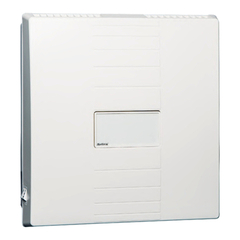
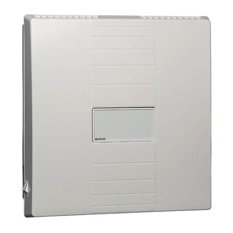
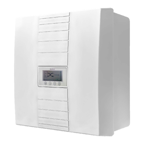
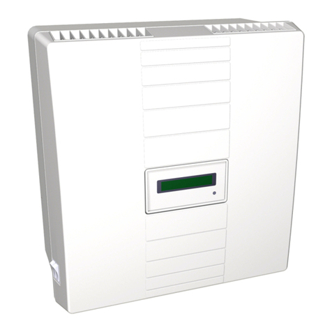
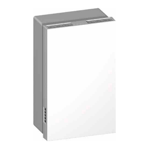
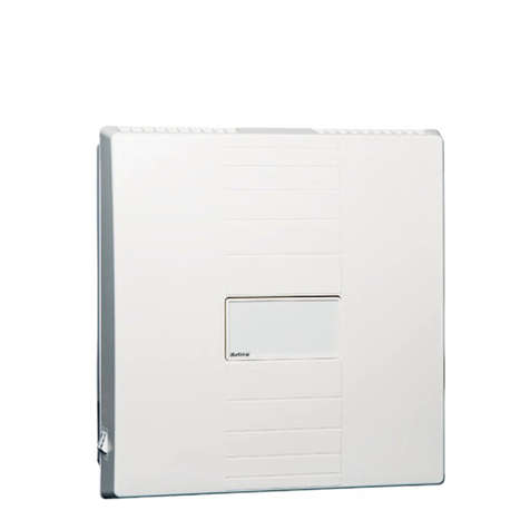
Meltem M-WRG-II Series User manual

Meltem Wärmerückgewinnung GmbH & Co. KG
Am Hartholz 4 · D-82239 Alling
VENTILATION THE RIGHT WAY
VENTILATION & HEAT RECOVERY
DISMANTLING INSTRUCTIONS
HOME VENTILATION WITH HEAT RECOVERY
Dismantling ventilation units
from the M-WRG-II series
at the end of the
product life cycle
Part no. 744016EN Week 11/2021 EN

Dismantling instructions
Ventilation units from the M-WRG-II series
- 2 -
Meltem Wärmerückgewinnung GmbH & Co. KG
Am Hartholz 4 · D-82239 Alling
VENTILATION THE RIGHT WAY
VENTILATION & HEAT RECOVERY
Contents
1 Introduction ................................................................................................................... 3
1.1 Notes on these dismantling instructions ......................................................................... 3
1.2 Description ...................................................................................................................... 3
1.3 Target group .................................................................................................................... 3
1.4 Environmentally-friendly disposal ................................................................................... 3
1.5 Revision index ................................................................................................................ 3
1.6 Explanation of the symbols used .................................................................................... 4
2 Safety instructions ....................................................................................................... 4
2.1 Hazardclassication ....................................................................................................... 4
2.2 Notes on dismantling the ventilation units ...................................................................... 4
3 Tools and equipment required ..................................................................................... 5
4 Dismantling the ventilation unit .................................................................................. 5
4.1 Detach electrical connections and uninstall the ventilation unit ...................................... 5
4.2 Remove the unit cover .................................................................................................... 6
4.3 Removetheairlters ...................................................................................................... 6
4.4 Remove the electronics compartment covers and intermediate plate ............................ 7
4.5 Remove the heat exchanger ........................................................................................... 7
4.6 Remove the exhaust air and supply air fans ................................................................... 8
4.7 Remove the sensors ....................................................................................................... 8
4.8 Remove the interface and control PCBs ......................................................................... 9
4.9 Remove the distributor PCB ........................................................................................... 9
4.10 Remove insulation and seals from the housing back panel .......................................... 10
4.11 Detach switch from electronics compartment cover ..................................................... 10
4.12 Removeapmotorsforairaps .................................................................................... 11
4.13 Disposal of the components .......................................................................................... 11
5 Material list .................................................................................................................. 12
Dismantling instructions
Ventilation units from the M-WRG-II series
- 3 -
Meltem Wärmerückgewinnung GmbH & Co. KG
Am Hartholz 4 · D-82239 Alling
VENTILATION THE RIGHT WAY
VENTILATION & HEAT RECOVERY
1 Introduction
1.1 Notes on these dismantling instructions
These instructions contain important information that should be followed when disman-
tling ventilation units from the M-WRG-II series at the end of the product life cycle.
►Read all the instructions carefully before dismantling the ventilation unit to avoid
possible risks and mistakes.
WARNING
►Follow ALL danger and warning instructions and notes on precautionary measures.
►Read section “2 Safety instructions” on page 4 carefully.
1.2 Description
These instructions describe the dismantling of ventilation units from the M-WRG-II series
at the end of the product life cycle.
1.3 Target group
Thesedismantlinginstructionsareaimedattwodierenttargetgroups:
— The activities described in section “4.1 Detach electrical connections and uninstall the
ventilation unit” on page 5 must only be carried out by specialised personnel with
thefollowingqualications:
— Training in the installation and commissioning of electrical devices
— Training in electrical hazards and the local safety requirements
— Knowledge of the relevant standards and directives
— Knowledge and observance of this document and all the safety instructions
— Nospecialpriorknowledgeisneededforallotheractivitiesexcludingthosespecied
in section 4.1.
1.4 Environmentally-friendly disposal
The components of the ventilation unit must not be disposed of in the residual waste bin.
►Dispose of the components of the ventilation unit in accordance with the waste
disposal regulations that apply on site.
1.5 Revision index
Edition Manual Date
1st edition Dismantling of ventilation units from the
M-WRG-II series at the end of the product life cycle
Week 11/2021 EN

Dismantling instructions
Ventilation units from the M-WRG-II series
- 4 -
Meltem Wärmerückgewinnung GmbH & Co. KG
Am Hartholz 4 · D-82239 Alling
VENTILATION THE RIGHT WAY
VENTILATION & HEAT RECOVERY
1.6 Explanation of the symbols used
►This symbol indicates an action to be taken.
— This symbol indicates a list.
2 Safety instructions
These instructions contain notes that you must follow for your own personal safety and to
avoid injury and damage to property. They are highlighted by warning triangles and are
shown as follows according to the level of danger.
2.1 Hazard classication
DANGER
The signal word designates a hazard with a high degree of risk which, if it is not
avoided, will result in death or severe injury.
WARNING
The signal word designates a hazard with a medium degree of risk which, if it is not
avoided, will result in death or severe injury.
CAUTION
The signal word designates a hazard with a low degree of risk which, if it is not avoided,
could result in minor or moderate injury.
NOTICE
A note as used in this manual contains important information about the product or about
a part of the manual to which particular attention should be paid.
2.2 Notes on dismantling the ventilation units
Ventilation units from the M-WRG-II series must only be dismantled if the following condi-
tionsarefullled:
— The electrical connections on the ventilation unit have been disconnected by a quali-
edelectrician.
— The ventilation unit has been removed from its original installation location making it
easily accessible for dismantling.
— The ventilation unit has been placed on a suitable work surface for dismantling.

Dismantling instructions
Ventilation units from the M-WRG-II series
- 5 -
Meltem Wärmerückgewinnung GmbH & Co. KG
Am Hartholz 4 · D-82239 Alling
VENTILATION THE RIGHT WAY
VENTILATION & HEAT RECOVERY
3 Tools and equipment required
— Set of cross-head screwdrivers
— Set of slotted screwdrivers
— Torx screwdriver TX10
— Torx screwdriver TX20
4 Dismantling the ventilation unit
4.1 Detach electrical connections and uninstall the ventilation unit
DANGER
Potentially fatal voltages
— Onlyqualiedelectriciansmayworkontheelectricalinstallation.
— The VDE regulations or any special safety regulations applicable in your country
apply to the electrical installation work.
►Before starting to uninstall, disconnect the mains cable and the control cable (if
used) on all poles from the main power supply.
► Observethevesafetyrules(DINVDE0105-100,EN50110-1)forworkingonelec-
tricalsystems:
— Disconnect from mains (all-pole disconnection of a system from live parts)
— Secure against reconnection
— Check that the system is voltage-free
— Earth and short-circuit
— Coverorblockoaccesstoadjacentliveparts
►Detach the electrical connections from the ventilation unit.
►Uninstall the ventilation unit from its installation location.
►Place the ventilation unit on a suitable work surface for the rest of the dismantling
work.

Dismantling instructions
Ventilation units from the M-WRG-II series
- 6 -
Meltem Wärmerückgewinnung GmbH & Co. KG
Am Hartholz 4 · D-82239 Alling
VENTILATION THE RIGHT WAY
VENTILATION & HEAT RECOVERY
4.2 Remove the unit cover
Fig.1: Removing the cover from the ventilation unit
11
2
►Using both thumbs, press the two latches
(item 1 in Fig. 1) on the bottom of the venti-
lation unit. The unit cover (item 2 in Fig. 1)
will come away.
► Atthesametime,pushyourindexngers
into the gap between the unit cover and
housing, and lift the unit cover up and away
from the housing.
►Pull away the black insulation on the back of
the unit cover.
4.3 Remove the air lters
Fig.2: Removetheairlters
1
2
► Usingthehandgrip,turnthelterring
(item1inFig.2)anti-clockwiseuntilthelter
ring is released from the retainers.
► Pullthelterringtogetherwiththeextractair
lteroutoftheventilationunit.
► Usingthehandgrip,turntheltercover
(item2inFig.2)anti-clockwiseuntilthelter
cover is released from the retainers.
► Pulltheltercovertogetherwiththeoutdoor
airlteroutoftheventilationunit.

Dismantling instructions
Ventilation units from the M-WRG-II series
- 7 -
Meltem Wärmerückgewinnung GmbH & Co. KG
Am Hartholz 4 · D-82239 Alling
VENTILATION THE RIGHT WAY
VENTILATION & HEAT RECOVERY
4.4 Remove the electronics
compartment covers and
intermediate plate
Fig.3: Remove the electronics compartment covers and
intermediate plate
1
1
2
2
3
4
5
6 6
►Use the Torx screwdriver TX10 to loosen the
two screws (item 1 in Fig. 3) on the elec-
tronics compartment covers.
►Lift the two electronics compartment covers
(item 2 in Fig. 3) away.
►On the electronics compartment cover with
theOn/Oswitch,detachtheconnecting
cable from the PCB in the ventilation unit.
►Remove the seal (item 3 in Fig. 3) with a
slotted screwdriver.
►Use the Torx screwdriver TX20 to loosen the
13 screws (item 4 in Fig. 3) on the interme-
diate plate.
►Lift up the intermediate plate (item 5 in
Fig. 3) with the two air grilles (item 6 in
Fig. 3).
►Remove the intermediate plate seal on the
back of the intermediate plate.
4.5 Remove the heat exchanger
Fig.4: Remove the heat exchanger
1
2
4
4
3
3
3
3
3
3
►Remove the seal (item 1 in Fig. 4) from the
electronics compartment.
►Lift out the heat exchanger (item 2 in Fig. 4).
► Removethe6sealingproles(item3in
Fig. 4).
► Removethelterchannelinsulationpieces
(item 4 in Fig. 4) on the extract air and
supply air sides.

Dismantling instructions
Ventilation units from the M-WRG-II series
- 8 -
Meltem Wärmerückgewinnung GmbH & Co. KG
Am Hartholz 4 · D-82239 Alling
VENTILATION THE RIGHT WAY
VENTILATION & HEAT RECOVERY
4.6 Remove the exhaust air and
supply air fans
Fig.5: Remove the exhaust air and supply air fans
1
2
3
4
►Pull the exhaust air fan (item 1 in Fig. 5) up
and out.
►Remove the black retaining clip (item 2 in
Fig. 5) from the exhaust air fan with a slotted
screwdriver.
►Detach the two plug connectors (item 3 in
Fig. 5) from the exhaust air fan.
►Remove the exhaust air fan.
►Repeat the process for the supply air fan
(item 4 in Fig. 5).
4.7 Remove the sensors
Fig.6: Remove the sensors
1
1
►Remove the sensors (item 1 in Fig. 6) from
the holders.
►Detach the sensors from the ribbon cables.
NOTICE
The number of installed sensors will depend
on the type of ventilation unit.

Dismantling instructions
Ventilation units from the M-WRG-II series
- 9 -
Meltem Wärmerückgewinnung GmbH & Co. KG
Am Hartholz 4 · D-82239 Alling
VENTILATION THE RIGHT WAY
VENTILATION & HEAT RECOVERY
4.8 Remove the interface and control
PCBs
Fig.7: Remove the interface and control PCBs
1
2
3
4
5
6
►Loosen the two Torx screws TX10 (item 1
in Fig. 7) on the interface PCB (item 2 in
Fig. 7).
►Take out the interface PCB and detach the
connecting cable.
►Lift the antenna holder (item 3 in Fig. 7) with
thelmantennaandcontrolPCB(item4in
Fig. 7) up and out.
►Detach all the plug-in connections from the
control PCB.
►Remove the black housing internal seal
(item 5 in Fig. 7) that fully covers the base of
the housing.
►Detach the membrane keypad (item 6 in
Fig. 7) on the side of the housing.
4.9 Remove the distributor PCB
Fig.8: Remove the distributor PCB
1
2
3
4
►Remove the holder (item 1 in Fig. 8) over the
distributor PCB.
►Detach the plug-in connections from the
distributor PCB (item 2 in Fig. 8).
►Use a screwdriver to lift up the distributor
PCB.
►Remove all cables and wires (item 3 in
Fig. 8) from the housing (item 4 in Fig. 8).

Dismantling instructions
Ventilation units from the M-WRG-II series
- 10 -
Meltem Wärmerückgewinnung GmbH & Co. KG
Am Hartholz 4 · D-82239 Alling
VENTILATION THE RIGHT WAY
VENTILATION & HEAT RECOVERY
4.10 Remove insulation and seals
from the housing back panel
Fig.9: Remove insulation and seals from the housing
back panel
2
1
►Turn the ventilation unit so that the back
panel points up.
►Detach the two sealing rings (item 1 in
Fig. 9) from the air spigots.
►Detach the black insulation (item 2 in Fig. 9)
from the housing back panel.
4.11 Detach switch from electronics
compartment cover
Fig.10: Detach switch from electronics compartment
cover
1
2
►Press the two retaining tabs together on the
back of the mains switch (item 1 in Fig. 10).
►Slide the switch with the cable harness
forward out of the electronics compartment
cover (item 2 in Fig. 10).

Dismantling instructions
Ventilation units from the M-WRG-II series
- 11 -
Meltem Wärmerückgewinnung GmbH & Co. KG
Am Hartholz 4 · D-82239 Alling
VENTILATION THE RIGHT WAY
VENTILATION & HEAT RECOVERY
4.12 Remove ap motors for air aps
Fig.11: Removeapmotorsforairaps
1
23
►Use a screwdriver to lift the connection PCB
(item1inFig.11)fortheapmotorothe
removed supply air and exhaust air fan.
►Push the retaining clips (item 2 in Fig. 11)
fortheapmotoroutwardsandpulltheap
motor(item3inFig.11)otheremoved
supply air and exhaust air fan.
4.13 Disposal of the components
►Dispose of the components separated in the
previous steps. There is a list of materials in
Table 1 on page 12.

Dismantling instructions
Ventilation units from the M-WRG-II series
- 12 -
Meltem Wärmerückgewinnung GmbH & Co. KG
Am Hartholz 4 · D-82239 Alling
VENTILATION THE RIGHT WAY
VENTILATION & HEAT RECOVERY
5 Material list
Component Material Item in g.
Air grille ABS Item 6 in Fig. 3
Electronics compartment covers ABS Item 2 in Fig. 3
Housing ABS Item 4 in Fig. 8
Intermediate plate ABS Item 5 in Fig. 3
Unit cover ABS Item 2 in Fig. 1
Extractairlter ABS/ltermedium Item 1 in Fig. 2
Outdoorairlter ABS/ltermedium Item 2 in Fig. 2
Heat exchanger Aluminium/plastic Item 2 in Fig. 4
Intermediate plate seal Cellular rubber
EPDM
Item 5 in Fig. 3
Sealingproles Elastomers Item 3 in Fig. 4
Sealing rings on air spigots Elastomers Item 1 in Fig. 9
Cables Electrical component –
ConnectionPCBforapmotor Electrical component Item 1 in Fig. 11
Control PCB Electrical component Item 4 in Fig. 7
Distributor PCB Electrical component Item 2 in Fig. 8
Exhaust air fan Electrical component Item 1 in Fig. 5
Flap motor Electrical component Item 3 in Fig. 11
Interface PCB Electrical component Item 2 in Fig. 7
Mains switch Electrical component Item 1 in Fig. 10
Membrane touch pad Electrical component Item 6 in Fig. 7
Ribbon cables Electrical component –
Sensors Electrical component Item 1 in Fig. 6
Supply air fan Electrical component Item 4 in Fig. 5
Housing internal seal EPDM Item 5 in Fig. 7
Holder over distributor PCB PE foam Item 1 in Fig. 8
Insulation on housing back panel PE foam Item 2 in Fig. 9
Seal in the electronics compartment PE foam Item 1 in Fig. 4
Antennaholderwithlmantenna PE foam/electrical
component
Item 3 in Fig. 7
Filter cover PS Item 2 in Fig. 2
Filter ring PS Item 1 in Fig. 2
Insulation on back of the unit cover PU foam Item 2 in Fig. 1
Filter channel insulation pieces for extract
air/supply air
PU/PE foam Item 4 in Fig. 4
Screws Steel –
Table1: Material list for the components installed in the M-WRG-II ventilation unit

Dismantling instructions
Ventilation units from the M-WRG-II series
- 13 -
Meltem Wärmerückgewinnung GmbH & Co. KG
Am Hartholz 4 · D-82239 Alling
VENTILATION THE RIGHT WAY
VENTILATION & HEAT RECOVERY
Space for your notes

Meltem Wärmerückgewinnung GmbH & Co. KG
Am Hartholz 4 · D-82239 Alling
VENTILATION THE RIGHT WAY
VENTILATION & HEAT RECOVERY
We have checked the content of this publication for conformity with the unit described in it. There may nevertheless still
bedierences,sowecannotguaranteecompleteaccuracy.
The information in this publication is regularly checked and any necessary corrections are made in subsequent editions.
Copyright © Meltem Wärmerückgewinnung GmbH & Co. KG We reserve the right to make changes.
Meltem Wärmerückgewinnung GmbH & Co. KG
Am Hartholz 4
D-82239 Alling
Germany
Tel. +49 8141 404179-0
Fax +49 8141 404179-9
Internet:www.meltem.com
Email:[email protected]
Go to
Meltem download area
CERTIFIED
COMPONENT
Passive House Institute
cool, temperate climate
Table of contents
Other Meltem Fan manuals

Meltem
Meltem M-WRG-II P Series Technical specifications

Meltem
Meltem M-WRG-Z-T User manual

Meltem
Meltem 5010 User manual

Meltem
Meltem M-WRG-II M User manual

Meltem
Meltem M-WRG/ZNH-F User manual

Meltem
Meltem M-WRG-S User manual

Meltem
Meltem M-WRG-II User manual

Meltem
Meltem M-WRG-M/MB-FR75/1 User manual

Meltem
Meltem M-WRG-S/Z-T User manual

Meltem
Meltem M-WRG-S/Z-T User manual

Meltem
Meltem M-WRG-II M User manual

Meltem
Meltem M-WRG-K User manual

Meltem
Meltem M-WRG-ES User manual

Meltem
Meltem M-WRG-S/Z-S User manual

Meltem
Meltem M-WRG-II ES-P User manual

Meltem
Meltem M-WRG-II M-U2 User manual

Meltem
Meltem M-WRG-K User manual

Meltem
Meltem M-WRG-II P-M User manual

Meltem
Meltem M-WRG-II P-T User manual