Eurosound HDBT70RxP User manual

HDBT70RxP
HDBaseT Receiver
All Rights Reserved
Version: HDBT70RxP_2016V1.0
User Manual

HDBaseT Receiver
SAFETY PRECAUTIONS
To insure the best from the product, please read all instructions carefully before using
the device. Save this manual for further reference.
Unpack the equipment carefully and save the original box and packing material for
possible future shipment
Follow basic safety precautions to reduce the risk of fire, electrical shock and injury
to persons.
Do not dismantle the housing or modify the module. It may result in electrical shock
or burn.
Using supplies or parts not meeting the products’ specifications may cause damage,
deterioration or malfunction.
Refer all servicing to qualified service personnel.
To prevent fire or shock hazard, do not expose the unit to rain, moisture or install this
product near water.
Do not put any heavy items on the extension cable in case of extrusion.
Do not remove the housing of the device as opening or removing housing may
expose you to dangerous voltage or other hazards.
Install the device in a place with fine ventilation to avoid damage caused by
overheat.
Keep the module away from liquids.
Spillage into the housing may result in fire, electrical shock, or equipment damage. If
an object or liquid falls or spills on to the housing, unplug the module immediately.
Do not twist or pull by force ends of the optical cable. It can cause malfunction.
Do not use liquid or aerosol cleaners to clean this unit. Always unplug the power to
the device before cleaning.
Unplug the power cord when left unused for a long period of time.
Information on disposal for scrapped devices: do not burn or mix with general
household waste, please treat them as normal electrical wastes.

HDBaseT Receiver
NOTICE: Please read this user manual carefully before using this product.
Pictures shown in this manual are for reference only. Different model and
specifications are subject to real product.
This manual is for operation instruction only, not for any maintenance usage.
Compared to the former HDBT70RxP user manual version, this version removes
the built-in IR receiver and adds collocation products. The functions described in
this version are updated till October 2016.Any changes of functions and
parameters since then will be informed separately. Please refer to the dealers for
the latest details.
This manual is copyright Eurosound. All rights reserved. No part of this publication
may be copied or reproduced without the prior written consent of Eurosound.
All product function is valid till 2016-10-27.

HDBaseT Receiver
Table of Contents
1. Introduction.................................................................................................................1
1.1 Introduction to HDBT70RxP ..............................................................................1
1.2 Features ............................................................................................................1
1.3 Packing List.......................................................................................................1
2. Panel Description........................................................................................................2
3. System Connection.....................................................................................................4
3.1 Usage Precautions............................................................................................4
3.2 System Diagram................................................................................................4
3.3 Connection Procedure.......................................................................................4
3.4 Application.........................................................................................................5
3.5 Twisted Pair Cable Connection..........................................................................5
4. Specification................................................................................................................6
4.1 Supported Resolution........................................................................................7
5. Panel Drawing ............................................................................................................8
6. Troubleshooting & Maintenance .................................................................................9
7. After-sales Service....................................................................................................10

HDBaseT Receiver
1
1. Introduction
1.1 Introduction to HDBT70RxP
HDBT70RxP is a mini-size HDBaseT Receiver which adopts HDBaseT technology to
receive high-resolution 1080p/ 4k signal from HDBaseT transmitter via a CAT5e/CAT6a
cable at a distance of up to 70/40m. Moreover, it support CEC, bi-directional RS232&IR
control, and bi-directional PoH function.
1.2 Features
Support Full HD: Delivers high resolution image (1080p@60Hz@48
b/pixels/3D/4Kx2K).
Maximum transmission distance is 70m for 1080p and 40m for 4Kx2K over single
CAT5e/CAT6a cable
High Bandwidth: 10.2Gps.
HDTV Compatible, use HDMI 1.4 and HDCP2.2 compliant.
Support CEC/IR/RS232 pass through.
Support bi-directional PoH.
Bi-directional RS232/IR control.
Use HDBaseT technology.
LED indicators show work status.
Note: Please use a CAT5e cable with low impedance (Shielded twisted pair will be
better and should be well grounded)for good transmission effect.
1.3 Packing List
1 x Receiver (HDBT70RxP)
2 x Mounting ears
4 x Screws
4 x Plastic cushions
1 x Power adapter (DC 24V 1.25A)
2 x RS232 cables
1 x User manual
Note:Please confirm if the product and the accessories are all included, if not, please
contact with the dealers.
HDBaseT Receiver
2
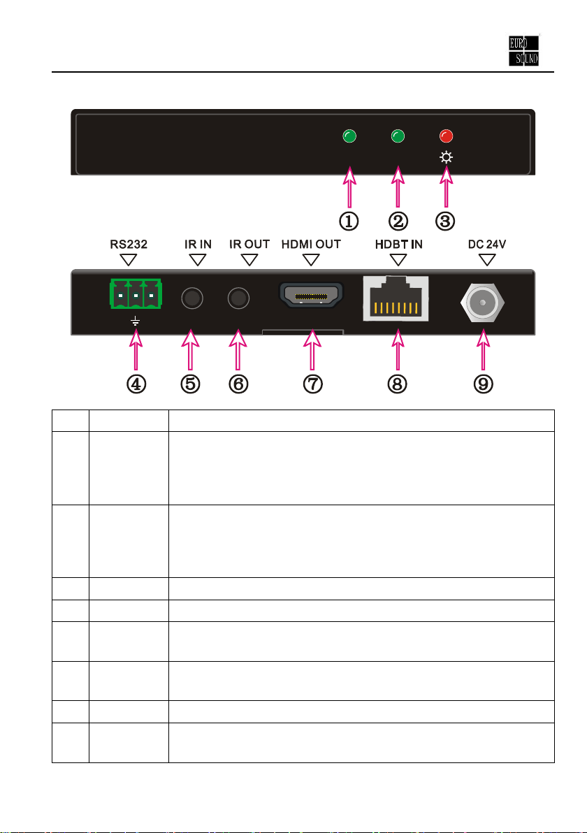
2. Panel Description
HDCPLINK
RX
RXTX
No.
Name
Description
①
LINK
HDBT Link status indicator:
OFF: No Link
GREEN:Link Successful
Blinking GREEN: Link abnormal
②
HDCP
HDCP compliant indicator
OFF: No HDMI traffic (no picture)
GREEN: Traffic with HDCP.
Blinking GREEN: Traffic without HDCP
③
Power
OFF: No power; RED: DC power present.
④
RS232
RS232 connector.
⑤
IR IN
Connect with 5V IR receiver (with carrier) to collect infrared signal,
work with far-end IR OUT port
⑥
IR OUT
Connect with 5V IR Emitter to send infrared signal, work with
far-end IR IN port
⑦
HDMI OUT
Connect with HDMI display
⑧
HDBT IN
Connect to the HDBT OUT socket on HDBaseT Transmitter via
CAT5e/ CAT6a cable.

HDBaseT Receiver
3
⑨
DC 24V
Connect with power supply (Not necessary if HDBaseT Transmitter
connects with power).
Pictures shown in this manual are only for reference.

HDBaseT Receiver
4
3. System Connection
3.1 Usage Precautions
1) System should be installed in a clean environment and has a prop temperature and
humidity.
2) All of the power switches, plugs, sockets and power cords should be insulated and
safety.
3) All devices should be connected before power on.
4) Use shielded straight-thru CAT5e/CAT6a cable with TIA/EIAT568B terminations for
good transmission effect.
3.2 System Diagram
DVD
HDMI
HDMI
INPUT
RS232
Controlpanel
Projector
IR Remote
HDBT70RxP
HDBaseTTransmitter
CAT5e
3.3 Connection Procedure
Step1.Connect HDMI source (such as Blue-ray DVD) to HDMI IN port of HDBaseT
Transmitter with HDMI cable.
Step2.Connect HDBT OUT port of HDBaseT Transmitter and HDBT IN port of
HDBT70RxP, with single CAT5e/CAT6a cable.
Step3.Connect HDMI displayer (such as HDTV) to HDMI OUT port of HDBT70RxP with
HDMI cable.
Step4.Both HDBaseT Transmitter and HDBT70RxP have IR IN and OUT. When one
end is used as an IR receiver, the signal sent from the end can only be
transmitted via the other end.
HDBaseT Receiver
5
For example: When “IR IN” of HDBaseT Transmitter connects with an IR
receiver, the IR emitter must connect to IR OUT of HDBT70RxP.
Step5.Connect the RS232 port of the devices to be controlled and the HDBT70RxP or
the HDBaseT Transmitter.
Step6.Connect with DC24V power adaptor(s) (One is enough if HDBaseT Transmitter
or HDBT70RxP is connected with adapter as its PoH function).
3.4 Application
This product has a good application in various occasions, such as computer realm,
monitoring, big screen displaying, meeting room, education and bank & securities
institution etc.
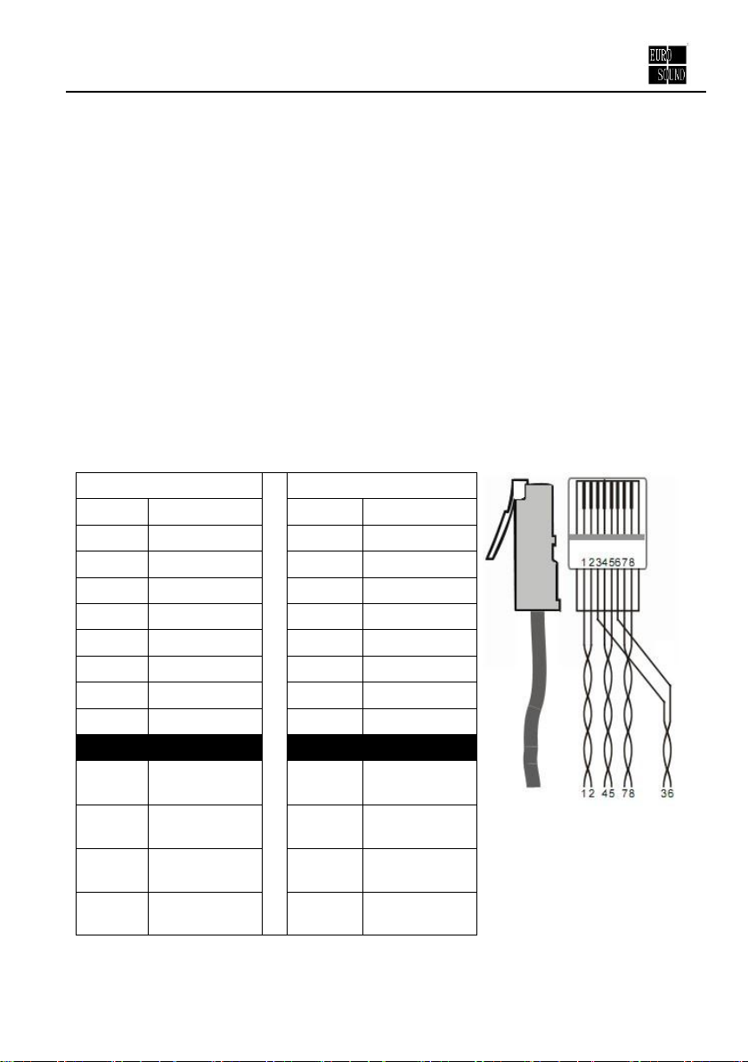
3.5 Twisted Pair Cable Connection
The twisted pair used in this Receiver MUST be a straight-through cable.
Notice: Cable connectors
MUST be metal one, the
shielded layer of cable
MUST be connected to the
connector’s metal shell, to
make a better transmission.
TIA/EIA T568A
TIA/EIA T568B
Pin
Cable color
Pin
Cable color
1
green white
1
orange white
2
green
2
orange
3
orange white
3
green white
4
blue
4
blue
5
blue white
5
blue white
6
orange
6
green
7
brown white
7
brown white
8
brown
8
brown
1st
Ground
4--5
1st
Ground
4--5
2nd
Ground
3--6
2nd
Ground
1--2
3rd
Group
1--2
3rd
Group
3--6
4th
Group
7--8
4th
Group
7--8
HDBaseT Receiver
6
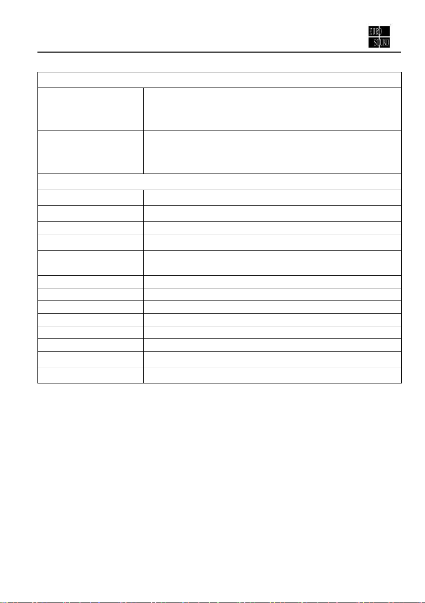
4. Specification
Input& Output
Input
1 IR (3.5mm mini jack)
1 HDBT (RJ-45)
1 RS232 (3-pin pluggable terminal block)
Output
1 HDMI (HDMI female)
1 IR (3.5mm mini jack)
1RS232 (3-pin pluggable terminal block)
General
Video Signal
HDMI 1.4 and HDCP2.2 compliant
Audio Signal
Digital audio, transmit through HDMI audio
Resolution Range
640x480@60Hz~4K×2K@30Hz
Transmission Mode
HDBaseT
Transmission Distance
1080p ≤70m
4Kx2K ≤40m
Bandwidth
10.2Gbps
Impedance
75Ω
Temperature
0~ 50℃
Humidity
10% ~ 90%
Power Supply
Input: 100VAC~240VAC, 50/60Hz Output: DC 24V, 1.25A
Power Consumption
14W
Dimension (W*H*D)
115mmx16.2mm x109mm
Net Weight
196g
NOTE: All nominal levels are at ±10%.

HDBaseT Receiver
7
4.1 Supported Resolution
Aspect Ratio
Resolution
Refresh Rate
4Kx 2K
4096x2160
30Hz
3840x2160
24/25/30Hz
16:9
1920x1080
60Hz
1600x900
60Hz
1366x768
60Hz
1280x720
60Hz
1024x576
60Hz
16:10
1920x1200
60Hz
1680x1050
60Hz
1360x768
60Hz
1280x800
60Hz
4:3
1600x1200
60/65/70/75/85Hz
1280x1024
60/75/85/96Hz
1024x768
60/70/75/85Hz
800x600
56/60/72/75/85Hz
640x480
60/72/75Hz
Note: This product supports 4k HDMI signal, please adopt quality HDMI cables
compliant with HDMI2.0 for reliable transmission.
HDBaseT Receiver
8
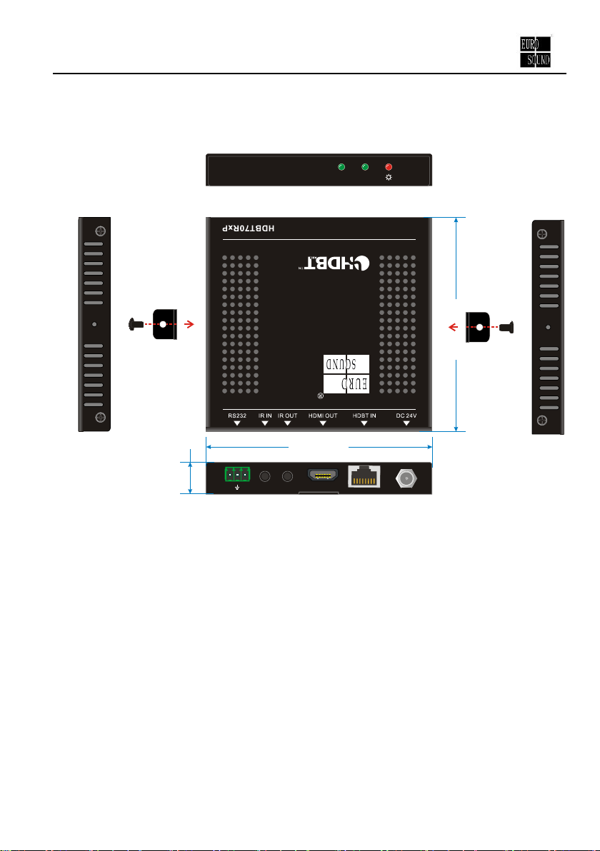
5. Panel Drawing
HDCPLINK
RX
RXTX
115 mm
109 mm
16.2 mm

HDBaseT Receiver
9
6. Troubleshooting & Maintenance
No image on display:
Ensure that the display device has been set to the correct input.
Ensure that the HDMI cables used for both the source/transmitter and the
receiver/display are properly connected and are working. Test the HDMI cables
directly from a source to display and ensure their operation.
Ensure that the CAT5e/CAT6a cable has not been damaged and that it has been
terminated correctly with T568B on both ends. A temporary length of
CAT5e/Cat6 can be used for testing to ensure that the devices are all compatible
and working properly.
Ensure proper grounding of the power supply.
Known issues with HDMI 1.2 source devices:
Older compatibility (HDMI 1.2) may result in HDBaseT transmission issues.
Please contact Technical Support of your director for a solution to these issues.
Color lose or poor picture quality:
Ensure that the HDMI cables used for both the source and transmitter and the
receiver and display are properly connected and are of good quality. Test the
HDMI cables directly from a source to display and ensure their picture quality.
Ensure proper grounding of the power supply.
If the static becomes stronger or picture quality becomes worse when connecting
the video connectors, this may be due to improper grounding.
Check the grounding and make sure all the components are properly grounded to
a common ground. Improper grounding may cause damage to the receiver.
If your problem persists after following the above troubleshooting steps, seek further
help from authorized dealer or our technical support.

HDBaseT Receiver
10
7. After-sales Service
If there appear some problems when running the device, please check and deal with the
problems reference to this user manual.Any transport costs are borne by the users
during the warranty.
1) Product Limited Warranty: Eurosound warrants that its products will be free from
defects in materials and workmanship for one years, which starts from the first day
the product leaves warehouse (The purchase invoice shall prevail).
Proof of purchase in the form of a bill of sale or receipted invoice which is evidence
that the unit is within the Warranty period must be presented to obtain warranty
service.
2) What the warranty does not cover:
Warranty expiration.
Factory applied serial number has been altered or removed from the product.
Damage, deterioration or malfunction caused by:
Normal wear and tear
Use of supplies or parts not meeting our specifications
No certificate or invoice as the proof of warranty.
The product model showed on the warranty card does not match with the
model of the product for repairing or had been altered.
Damage caused by force majeure.
Servicing not authorized by Eurosound
Any other causes which does not relate to a product defect
Delivery, installation or labor charges for installation or setup of the product
3) Technical Support: Email to our after-sales department or make a call, please
inform us the following information about your cases.
Product version and name.
Detailed failure situations.
The formation of the cases.


Other manuals for HDBT70RxP
1
Table of contents
Popular Receiver manuals by other brands


GE
GE TT3010 Installation/operation instructions warranty information

Petsafe
Petsafe UL-275 Operation manual

Yamaha
Yamaha RX-A1010 Easy setup guide

Sony
Sony STR-AV320 operating instructions

HP
HP x280n - MediaSmart Connect - Digital Multimedia... Installation and user guide

Kenwood
Kenwood KR-797 instruction manual