manuals.online logo
Brands
  1. Home
  2. •
  3. Brands
  4. •
  5. AMX
  6. •
  7. Receiver
  8. •
  9. AMX PMB-RF User manual

AMX PMB-RF User manual

Other AMX Receiver manuals

AMX AXD-IR Plus User manual

AMX

AMX AXD-IR Plus User manual

AMX AVB-TX-DGX-HD15-SC Fiber User manual

AMX

AMX AVB-TX-DGX-HD15-SC Fiber User manual

AMX MAX-AVM User manual

AMX

AMX MAX-AVM User manual

AMX Mio Moderno MIO-IRRX User manual

AMX

AMX Mio Moderno MIO-IRRX User manual

AMX AXR-IRSM Plus User manual

AMX

AMX AXR-IRSM Plus User manual

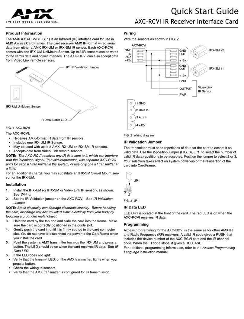
AMX AXC-RCVI User manual

AMX

AMX AXC-RCVI User manual

AMX AXR-RF User manual

AMX

AMX AXR-RF User manual

AMX Endeleo Multi-Format Receiver UDM-RX02 User manual

AMX

AMX Endeleo Multi-Format Receiver UDM-RX02 User manual

AMX PMB-IRI User manual

AMX

AMX PMB-IRI User manual

AMX DXLink User manual

AMX

AMX DXLink User manual

AMX DXLink User manual

AMX

AMX DXLink User manual

AMX DTV-RX02-HD User manual

AMX

AMX DTV-RX02-HD User manual

AMX UDM-RX02N User manual

AMX

AMX UDM-RX02N User manual

AMX Viewpoint AXR-RF User manual

AMX

AMX Viewpoint AXR-RF User manual

AMX MX8 User manual

AMX

AMX MX8 User manual

AMX AutoPatch Cat5 S-Video+Stereo TX User manual

AMX

AMX AutoPatch Cat5 S-Video+Stereo TX User manual

AMX DCP-SRX User manual

AMX

AMX DCP-SRX User manual

AMX Mio Moderno MIO-IRRX User manual

AMX

AMX Mio Moderno MIO-IRRX User manual

AMX Sensors and Receivers IR User manual

AMX

AMX Sensors and Receivers IR User manual

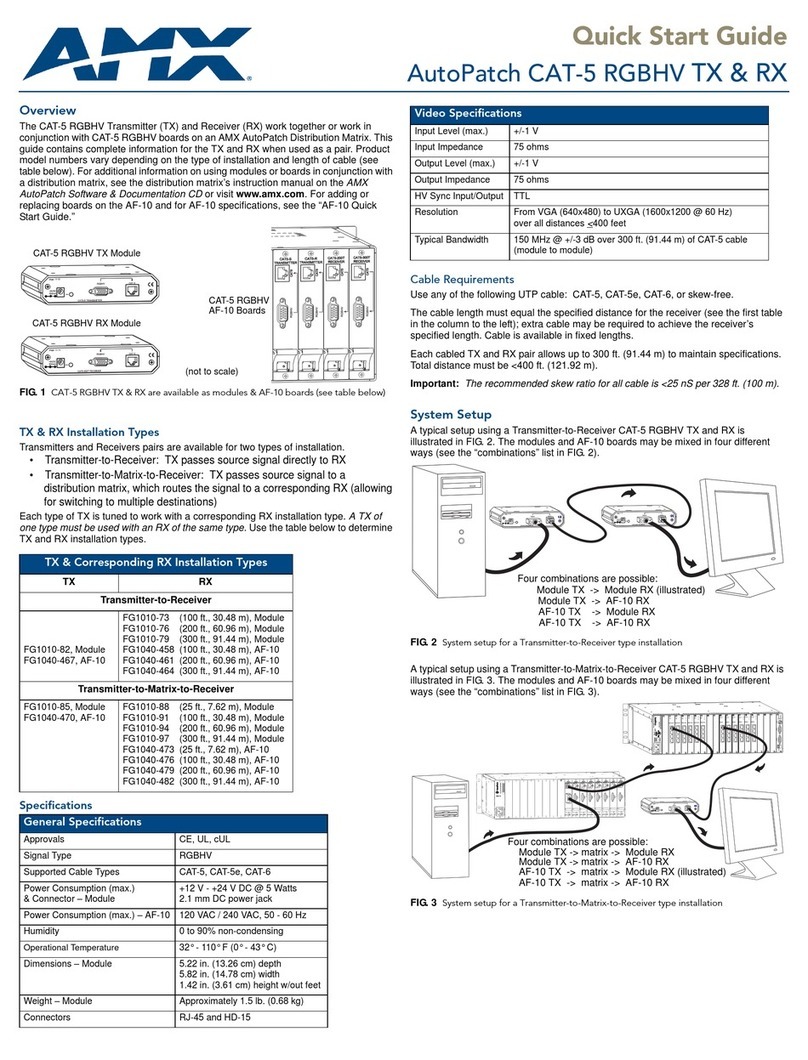
AMX AutoPatch CAT-5 RGBHV RX User manual

AMX

AMX AutoPatch CAT-5 RGBHV RX User manual

AMX AXU-IR User manual

AMX

AMX AXU-IR User manual

AMX DXLink User manual

AMX

AMX DXLink User manual

AMX AXD-IR Plus User manual

AMX

AMX AXD-IR Plus User manual

AMX DUX-SRX User manual

AMX

AMX DUX-SRX User manual

Popular Receiver manuals by other brands

Televes ZAS HD SAT user manual

Televes

Televes ZAS HD SAT user manual

Realistic DX-75 Operating and service instructions

Realistic

Realistic DX-75 Operating and service instructions

Saris 4620 Assembly instructions

Saris

Saris 4620 Assembly instructions

Mini DTR 206C PVR user manual

Mini

Mini DTR 206C PVR user manual

RF Elements TwistPort manual

RF Elements

RF Elements TwistPort manual

Denon DN-200WS user guide

Denon

Denon DN-200WS user guide

Yamaha RX-V467 owner's manual

Yamaha

Yamaha RX-V467 owner's manual

Russound SaphIR 858 instruction manual

Russound

Russound SaphIR 858 instruction manual

Quasonix RDMS Firmware update procedure

Quasonix

Quasonix RDMS Firmware update procedure

Pioneer XV-HTD1 Service manual

Pioneer

Pioneer XV-HTD1 Service manual

ATZ HDMI-V2-44HE150 manual

ATZ

ATZ HDMI-V2-44HE150 manual

Sony XNV-770BT MyTomTom Specifications

Sony

Sony XNV-770BT MyTomTom Specifications

Grundig STR 7122 TWIN Service manual

Grundig

Grundig STR 7122 TWIN Service manual

Creative Blaster Modem user guide

Creative

Creative Blaster Modem user guide

Panduit ATLONA AT-OME-RX11 installation guide

Panduit

Panduit ATLONA AT-OME-RX11 installation guide

VOLTCRAFT UTPS-40 operating instructions

VOLTCRAFT

VOLTCRAFT UTPS-40 operating instructions

JVC KW-ADV794 instructions

JVC

JVC KW-ADV794 instructions

Litelink VT-1001 operating instructions

Litelink

Litelink VT-1001 operating instructions

manuals.online logo
manuals.online logoBrands
  • About & Mission
  • Contact us
  • Privacy Policy
  • Terms and Conditions

Copyright 2025 Manuals.Online. All Rights Reserved.

Reference Guide
PMB-RF RF Receiver
Overview
The PMB-RF RF Receiver allows direct RF communications between a
PHAST system and the Viewpoint touch panel. This eliminates the need for
an AMX emulation card and the associated overhead of multiple-protocol
conversion.
The RF receiver supports the same transceivers as the AMX AXR-RF. Only
one PMB-RF can be used in a single Landmark system.
Safety Instructions
ATTENTION!
Read and follow all safety and operating instructions before installing or
operating this device. Adhere to all warnings listed on the device and in the
operating instructions.
• Disconnect this device from the power source before cleaning. Do not
use liquid or aerosol cleaners. Use only a clean, soft, damp cloth for
cleaning.
Installation and Operating
Caution: Many electronic components are static sensitive. If possible,
install these components in a static-free work environment. Otherwise,
touch a grounded metal object to discharge any static charge before han-
dling these components. Do not touch any live electrical conductors.
1. Check the RJ-45 connector(s) and wiring for proper function.
2. Plug the RJ-45 connector(s) into the RJ-45 socket(s) on the rear
panel. It does not matter which RJ-45 socket(s) you use.
3. Insert the 12VDC power supply plug into the +12VDC receptacle on
the rear panel. The center post is positive and the ring is negative.
4. Plug the power supply into a properly grounded 120VAC outlet. The
Power LED on the front panel should be illuminated.
5. When attaching this device to software in Landmark Designer, press
the ID button on the front panel to send the device ID information to
the Landmark system. This allows you to make the correct software
connection to this physical device in the Landmark system.
6. The RF LED flashes when RF data is received by the PMB-RF.
7. The Link LED flashes when data is sent from the PMB-RF to the Land-
mark system.
PHASTLink Cable Information
This section contains information that you will need to make PHASTLink
cables, plus general information on connecting PHASTLink devices.
PHASTLink cables are used to connect all PHASTLink-compatible devices,
including keypads, dimmers, J-box IR devices, amplifiers, audio switches,
etc. PHASTLink uses a standard 10Base-T connection (i.e. Category 5 wire
and RJ-45 connectors). The wire should be connected in the standard man-
ner, as shown in the following figure. If a consistent color code is used, wir-
ing problems will be minimized.
The system comes with a 15-port hub built into the cardframe (PLB-CF10).
The maximum length of wire per port is 1,000 feet. Each PHASTLink device
has two RJ-45 connectors to allow multiple devices to be daisy-chained on
one PHASTLink port. Refer to the PLB-CF10 documentation for more
detailed connection information.
The limit for each home run is 10 PHASTLink devices. Extra hubs can be
added to provide additional ports.
Note: Only one PHAST keypad can be used per port, so home-run each
keypad (FIG. 2).
For optimum performance, you must install a double 120-ohm terminator in
one of the RJ-45 jacks of the last device (or the only device) in a chain of
PHASTLink devices.
To build a double 120-ohm terminator:
1. Install a 120-ohm resistor (1/4-watt or larger) between pins 1 and 2 of
an RJ-45 connector.
2. Install a 120-ohm resistor (1/4-watt or larger) between pins 7 and 8 of
the same RJ-45 connector.
FIG. 1 PMB-RF RF Receiver
Specifications
Color Black
Data Bus 2 - RJ-45 PHASTLink connectors on rear panel
Power Supply 12 VDC, 1 Amp, DIN barrel connector on rear panel
Power Indicator Red LED on front panel
Link Indicator Green LED on front panel
RF Data Indicator Red LED on front panel
Identify One ID (identify) button on front panel
Antenna BNC RF connector on rear panel
Certification Certified for operation under FCC Part 15, Class B
Dimensions (HWD) .93" x 1.6" x 2.97" (2.36 cm x 4.06 cm x 7.54 cm)
Pin # Wire Color Polarity Function
1 White/Green + Transmit
2 Green - Transmit
3White/Orange -Mic
4Blue -Ground
5White/Blue +12VDC
6Orange +Mic
7White/Brown +Receive
8Brown -Receive
It is important that the correct pairing is observed. Transmit,
Receive, and Mic need to be on twisted pairs. Splitting pairs
(e.g., using a white/green wire with a blue/white wire for
transmit) will result in increased crosstalk, and may result in
bus failure or noise on the intercom.
FIG. 2 Home-run each PHAST keypad.
1 2 3 4 5 6 7 8
1 2 3 4 5 6 7 8
AMX Corporation reserves the right to alter specifications without notice at any time.
For full warranty information, refer to the AMX Instruction Manual(s) associated with your Product(s).
051-004-2433 11/01 ©2001 AMX Corporation. All rights reserved.
The AMX logo is a trademark of AMX Corporation. AMX reserves the right to alter specifications without notice at any time.
3000 research drive, richardson, TX 75082 USA • 469.624.8000 • 800.222.0193 • fax 469.624.7153 • technical support 800.932.6993
When connecting PHAST keypads that will be used as intercoms, the
Microphone Hub taps off the intercom audio signal carried on the
PHASTLink cable from that keypad.
PHAST LCD keypads must connect directly to a PHAST Hub (or PHAST
Microphone Hub). Due to power requirements and/or the need for a sepa-
rate microphone line for each keypad, they cannot be daisy-chained to
other LCD keypads. For maximum performance and reliability, a PHAST
keypad should be the only device on a home run to a port. PHASTLink
devices cannot be wired in a star configuration (see FIG. 3).
Troubleshooting Tips
If you are having difficulty receiving commands, check the following:
• Make sure there is only one RF receiver per Landmark system, and
that the RF receiver is positioned near the center of the home or
building and away from concentrations of other electronic equipment.
• Make sure the PMB-RF is not placed in any location that receives
direct or high levels of sunlight. Reposition if necessary.
• Start Landmark Designer and monitor the PMB-RF function in the
Network Log. Make a number of clean button-press commands. You
should see these come in on the correct port. Watch for any interfer-
ence from other ports.
• Check the remote mode when comparing programming functions.
Make sure the mode matches the appropriate programming mode.
• Verify the wire termination.
FIG. 3 PHASTLink devices cannot be wired in a star configuration