Eurotec BA S011 User manual

BA_S011
Operation Manual
EUROTEC Antriebszubehör GmbH | Bildstock 37 | DE-88085 Langenargen | sales@eurotec-shop.com | www.eurotec-shop.com | 19.11.2015 | Seite 1 von 5
Product group:
Limit switch box big-box
Product type:
EAL...
EN
Certificates:
EAL
Table of Contents
1. Device description.................................................................................................................................................................................................2
2. Intended use .........................................................................................................................................................................................................2
3. Labeling.................................................................................................................................................................................................................2
4. Safe installation ....................................................................................................................................................................................................2
5. Mounting on pneumatic actuators........................................................................................................................................................................3
6. Mounting on manual valves..................................................................................................................................................................................3
7. Electrical connection ............................................................................................................................................................................................3
8. Dismantling...........................................................................................................................................................................................................3
9. Setting of the swivel range ...................................................................................................................................................................................3
10. Connection of solenoid coils...............................................................................................................................................................................4
11. Outdoor use.........................................................................................................................................................................................................5
12. Maintenance........................................................................................................................................................................................................5
13. Malfunctions .......................................................................................................................................................................................................5
14. Part number........................................................................................................................................................................................................5
BA_S011
Operation Manual
EUROTEC Antriebszubehör GmbH | Bildstock 37 | DE-88085 Langenargen | sales@eurotec-shop.com | www.eurotec-shop.com | 19.11.2015 | Seite 2 von 5
Thank you for choosing a EUROTEC product. With this limit switch box you have purchased a quality product. To ensure functionality and for
your own safety, please read these operating instructions carefully before you begin the installation. If you have any further questions,
please contact:
EUROTEC Antriebszubehör GmbH
Tel. +49 (0) 7543 93463 - 0 | Fax. - 10 | sales@eurotec-shop.com | www.eurotec-shop.com
1. Device description
Limit switch boxes serve as position feedback and control unit of valves that are operated by pneumatic part turn actuators. The shaft of the
limit switch box is connected form-fit to the shaft of the actuator and will turn when you shift the actuator. The cams which are mounted on
the shaft of the limit switch box will then activate the switches which are responsible for the transmission of the electrical signal.
Depending on the model, the wave limit switch boxes contain 1 to 4 mechanical micro switches or inductive proximity switches, 1-3 slot type
sensors, 1 dual sensor, 1 potentiometer or 1-2 pneumatic switches. Additionally certified intrinsically safe proximity switches can be
installed.
2. Intended use
The standard big-box limit switch boxes from EUROTEC are suitable for use in non-hazardous areas. In case of installed intrinsically safe
proximity switches, the housings can be used in hazardous areas of Zone 1 and 21. In that case the part number will have an “-IA” included.
The ambient temperature range depends on the housing material and the integrated switch type. It is indicated on the referring technical
data sheet and on the product label.
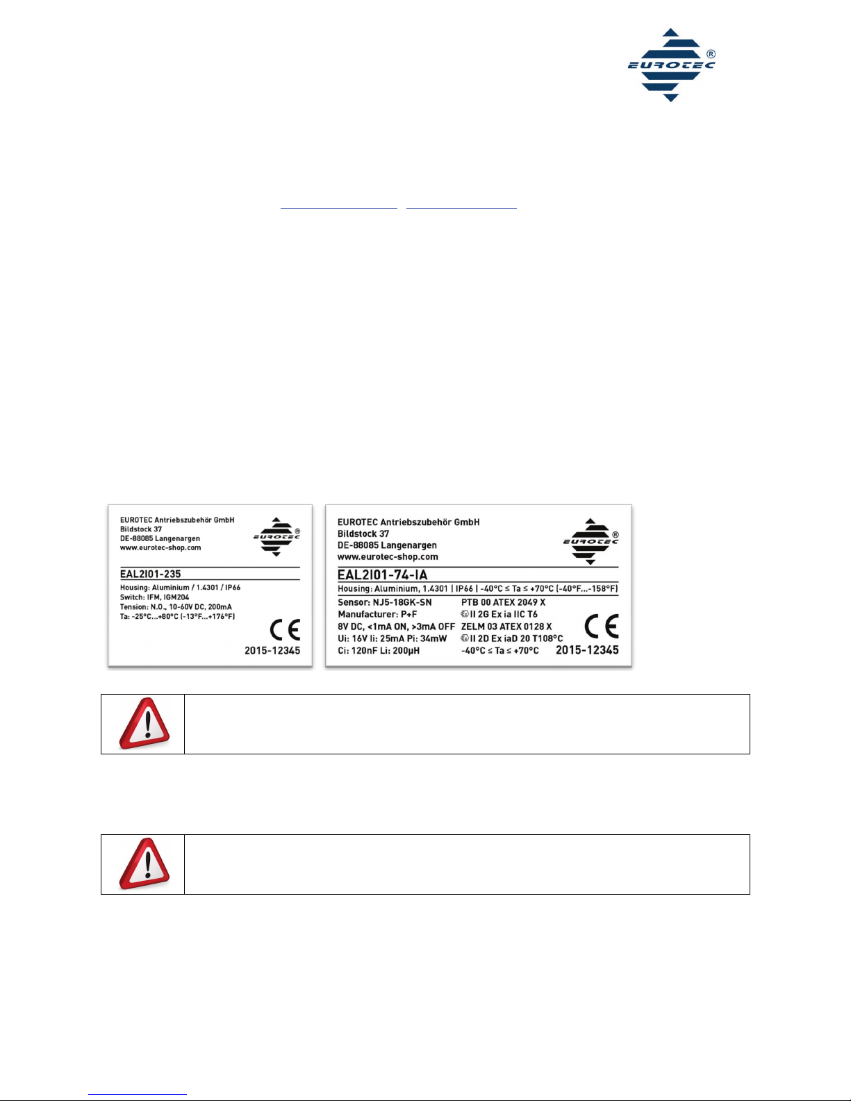
3. Labeling
The product label on the housing is shown in figure 1. Each switch type has it’s own label. The serial number is to be found below the CE
symbol. It contains the year of manufacture and the referring production number.
Fig. 1: Product label (without and with intrinsically safe switches)
Do not use the housings as ladder to climb in the facility. By doing so, the housings could be damaged and
affected in their function. Damaged housings are no longer protected against dirt and water. This can cause a
short circuit.
4. Safe installation
To avoid mistakes, only a specialist is permitted to set up, connect and put the devices into operation. Always observe the following safety
instructions before set up:
If you do not observe the safety instructions in these operational instructions or if you use or handle the device
improperly, our staff cannot be held liable. Furthermore your warranty for the device and its accessory
components will be void.
Verify if the classification on the label is appropriate to your application.
Please consider the respective national regulations and legal requirements, as well as the requirements of the manufacturer and the
generally accepted rules of technology.
Please take appropriate measures to avoid accidental activation and improper external influence.
Do not remove possibly existing cable entry devices until inserting the cables to ensure that any dirt remains outside the limit switch box.
Ensure an adequate strain-relief for the supply cable or a static installation.
Protect the equipment and cables effectively from any damage.
Avoid static charging of plastic parts and cables. Thereto clean the equipment only with an antistatic or wet cloth.
Connect all conductive metal parts, including accessories, to the potential equalisation.

BA_S011
Operation Manual
EUROTEC Antriebszubehör GmbH | Bildstock 37 | DE-88085 Langenargen | sales@eurotec-shop.com | www.eurotec-shop.com | 19.11.2015 | Seite 3 von 5
The equipment may only be operated in completely assembled status.
Never disconnect energised cables or systems.
5. Mounting on pneumatic actuators
The limit switch boxes can be mounted quickly and easily on your actuator with the delivered screws according to VDI/VDE 3845.
1. Bring the actuator in the end position in which the flute of the actuator shaft is in parallel to the actuator housing.
2. Attach the switch box with the suitable mounting bracket to the actuator.
3. The mounting bracket can now be fastened on the actuator with the 4 delivered screws.
4. Release the 4 cover screws and open the switch box. Do not unscrew them too far so that they do remain plugged into the cover.
5. Lead the system cable through the cable gland into the switch box housing and connect the individual leads to the terminal block.
Consider thereto the wiring diagram on the according data sheet or on the switch box cover and connect the housing to the potential
equalization.
6. Close the switch box with the cover. Take care that the sealing of the cover is in proper position and tighten the screws firmly.
6. Mounting on manual valves
The limit switch boxes with F05 interface at the bottom side of the housing can also be mounted on manual valves by using our mounting kit
“MSH”. Thereto your manual valve needs a top flange according to ISO 5211 (F03 - F16) and a threaded bore hole in the valve shaft. For
detailed assembly instructions please consider the operation manual of the “MSH”.
7. Electrical connection
The permitted sheath diameters are indicated on the according data sheet of the limit switch box. The circuit diagram is indicated on or
inside the limit switch box cover as well as on the according data sheet.
Take care that the cable gland body, which is mounted to the housing, does remain in it’s position when
tightening the cable gland nut. Please use 2 fork wrenches for this procedure. One to prevent the cable gland
body from turning and the other to tighten the cable gland nut. If the cable gland sealing leaves it’s proper
position, it will influence the level of the protection by enclosure (IP).
EUROTEC standard terminal block:
Wire cross section: 0,2 - 2,5mm2 (single-wire inflexible) / 0,25 - 2,5mm2 (single-wire flexible or with ferrule)
Stripping length: 7mm
Tightening torque: 0,5 - 0,6 Nm
Abb. 2: Standard terminal block
8. Dismantling
When dismantling, observe the instructions from chapter 3.
1. Disconnect the housing from the power supply.
2. Loosen the 4 cover screws and open the switch box. Do not unscrew them too far so that the screws do remain plugged into the cover.
3. Disconnect the system cable from the terminal block of the limit switch box.
4. Loosen the 4 screws that hold the mounting bracket on the actuator and remove the switch box from the actuator.
9. Setting of the swivel range
In delivered status the cams are always preset on a swivel range of 0 - 90°. If you need another swivel range, please proceed with the
following steps:
BA_S011
Operation Manual
EUROTEC Antriebszubehör GmbH | Bildstock 37 | DE-88085 Langenargen | sales@eurotec-shop.com | www.eurotec-shop.com | 19.11.2015 | Seite 4 von 5
1.
Rectangular V3 limit switches
a. Remove the visual indication. (Fig. 5)
b. Bring the actuator in the desired end position 1. Adjust the lower cam first. Press the cam down and turn it into the position in which
it actuates the switch. Now let the cam engage again with the toothing. (Fig. 6)
c. Bring the actuator in the desired end position 2. Press the upper cam down and turn it into the position in which it actuates the switch.
Now let the cam engage again with the toothing.
d. Finally verify your presetting through repeated switching.
e. Mount the visual indication to the shaft of the limit switch box.
Fig. 3: Removing indicator
Fig. 4: Cam setting
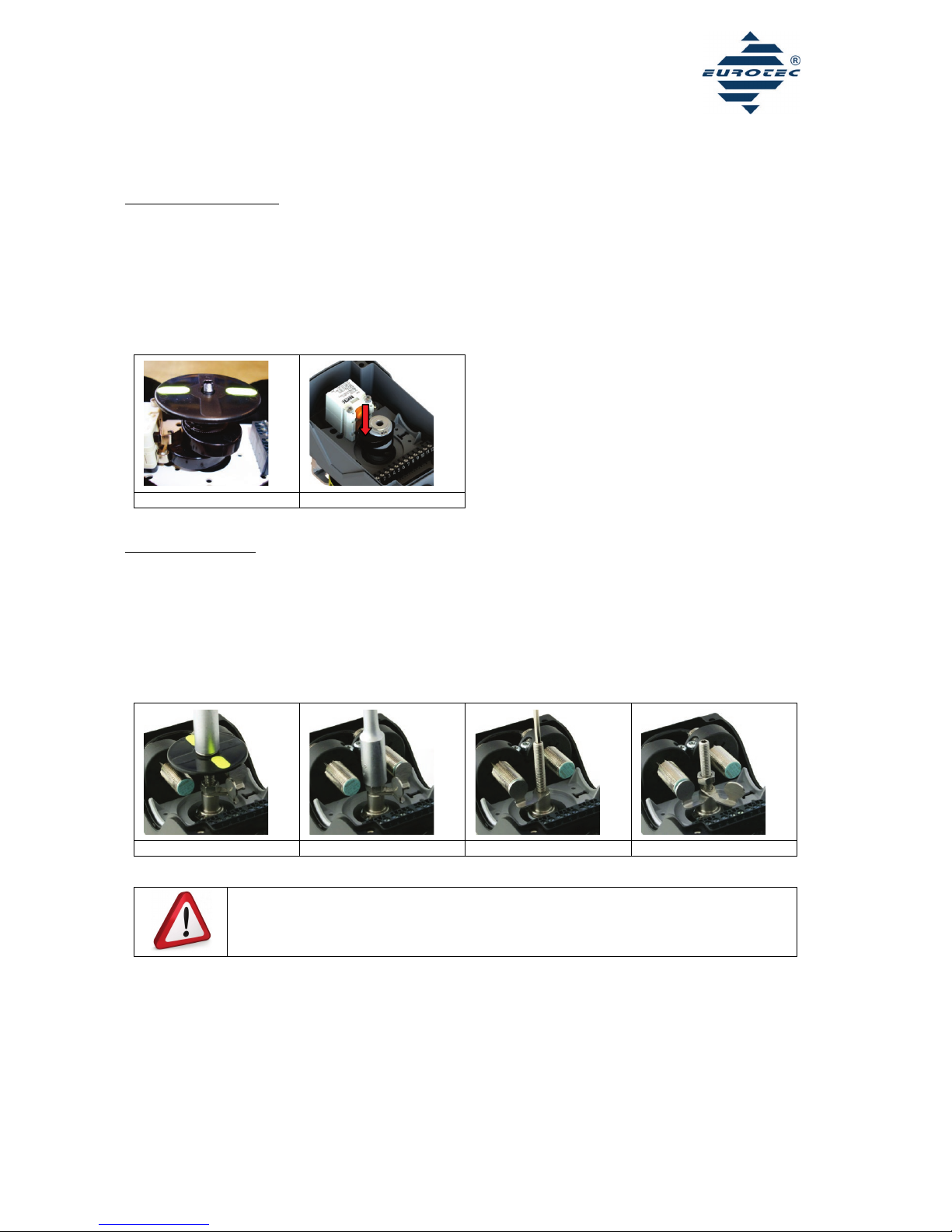
2.
Cylindrical limit switches
f. Remove the visual indication. (Fig. 7)
g. Loosen the M6 nut screw and remove the upper cam. (Fig.8)
h. Unfasten the threaded rod, bring the actuator in the desired end position 1, and adjust the lower cam. Then tighten the threaded rod
again firmly. (Fig. 9)
i. Bring the actuator in the desired end position 2, adjust the upper cam and tighten it again by means of the nut screw. (Fig. 10)
j. Finally verify your presetting through repeated switching of the actuator.
k. Mount the visual indication to the shaft of the limit switch box. Take care that the indication is in line with the upper end of the
threaded rod. This will prevent the indication from touching upon the fixture or the cover.
Fig. 5: Removing indicator
Fig. 6: Loosen nut screw
Fig. 7: Fixation of cam 1
Fig. 8: Fixation of cam 2
Danger of injury. During the switching process of the actuator you might squeeze body parts bet-
ween switch and cam. Stay far enough away from the source of danger when switching the actuator.
Attention, the switch can be damaged by the cams in the event of a wrong presetting. Take care that
the cam does not hit the switch when switching the actuator.
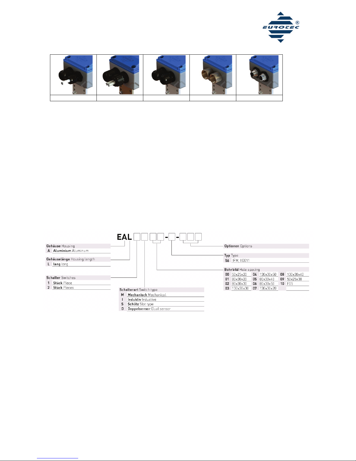
10. Connection of solenoid coils
Depending on the model, the limit switch boxes of EUROTEC provide the possibility to connect one or two solenoid coils inside the housing.
The suitable switch boxes for one coil are marked with an additional '-MA' in their part number. This version has a cable with a length of
500mm that is connected to the terminal block inside the housing and lead outside the housing through a cable gland. The leads of this
cable have to be wired to the plug connector of the solenoid coil. Please consider the coil manufacturer’s operation manual and the circuit
diagram on or inside the limit switch box cover or on the according technical data sheet. The same applies to the connection of two solenoid
coils. This version is marked with an additional '-2MA' in it’s part number and provides two cables with a length of 500mm each.
With the models “-2KV” and “-2NPT1/2” the solenoid valve connection is optional on poles 7-9.
BA_S011
Operation Manual
EUROTEC Antriebszubehör GmbH | Bildstock 37 | DE-88085 Langenargen | sales@eurotec-shop.com | www.eurotec-shop.com | 19.11.2015 | Seite 5 von 5
Fig. 9: -MA
Fig. 10: -2MA
Fig. 11: -2KV
Fig. 11: -2NPT1/2
Fig. 12: -MA12
11. Outdoor use
If you like to use the limit switch boxes for an outdoor application, you will need a venting element. This venting element will help to avoid
condensation water inside the switch box housing due to ambient temperature variations. Please verify if a venting element is present at
your limit switch box. Otherwise you need to order a suitable limit switch box with venting element. The order code “-DAE” needs to be
added to the actual part number.
12. Maintenance
With the long-term outdoor use of the switch boxes and with extremely high or low ambient temperatures, the cover and shaft sealings can
become porous. A safe use can only be guaranteed with a leak-proof housing. Sealings need to be replaced as soon as they are worn out,
but no later than after 5 years. The necessary sealings can be ordered from EUROTEC.
13. Malfunctions
If a malfunction occurs, check the electric line connections, the supply voltage, the cam position, condensation water inside the housing, the
proper function of the pneumatic actuator and of the valve below the actuator. Rectify any possible faults. If this does not rectify the
malfunction, be sure the there is no pressure on the device and disconnect the device from the power supply voltage. Consult an authorised
and trained specialist member of the manufacturer’s staff.
14. Part number
Table of contents
Other Eurotec Switch manuals


