manuals.online logo
Brands
  1. Home
  2. •
  3. Brands
  4. •
  5. FISCHER
  6. •
  7. Switch
  8. •
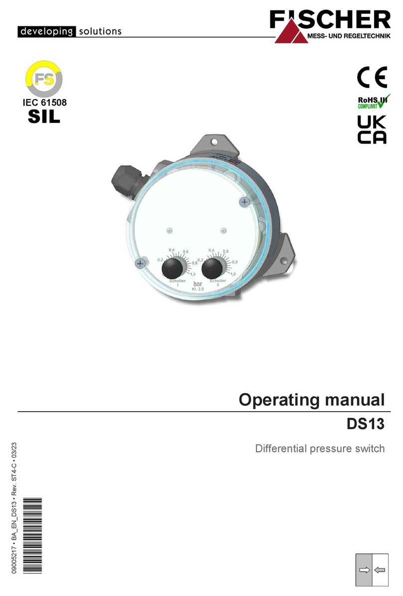
  9. FISCHER DE45 series Instruction Manual

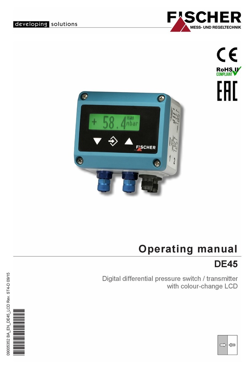
FISCHER DE45 series Instruction Manual

1. Safety Instructions
1.1. General
This manual contains detailed
information about the product
and instructions for its installa-
tion, operation and main-
tenance. Operators and other
technical personnel responsible for the equipment
must read this thoroughly before attempting to in-
stall or operate this equipment. A copy of this ma-
nual must always be kept accessible at the place
of work for reference by concerned personnel.
Chapter 1 sections 1.2 through 1.7) contains
general as well as specific safety instructions.
Chapters 2 through 10, covering topics ranging
from intended purpose of the equipment to its final
disposal, also include important points relating to
safety. Overlooking or ignoring any of these safety
points can endanger humans and animals, and
possibly cause damage to other equipment.
1.2. Personnel Qualification
Personnel responsible for installation, operation,
maintenance and inspection of this product must
have the qualifications, training and experience
necessary to carry out such work on this type of
equipment.
Qualified personnel are people who are able to ju-
dge delegated work and possible dangers due to
technical education, proficiency and experiences
and especially by knowledge about the relevant
norms.
When working with explosion proof constructed
instruments personnel needs to be educated or
instructed resp. have the authorisation to work
with explosion proof instruments in explosion-
hazardous plants.
Table of Contents
1. Safety Instructions
2. Intended Applications
3. Product Description and Functions
4. Installation
5. Commissioning
6. Maintenance
7. Transport
8. Service
9. Accessories
10. Disposal
11. Specifications
12. Dimensions
13. Ordering Code
14. Declaration of Conformity
Data Sheet and Instruction Manual
DE4 Digital Differential Pressure Switch / Transmitter
DE45##00###K0#M#R####
Gas Explosion Proof to Zone 2
Contact: EK Engineering (India)
Web: www.ekeindia.com
Email: [email protected]
All manuals and user guides at all-guides.com
all-guides.com
2
1.3. Risks of Disregarding Safety Instructions
Disregarding safety instructions, use of this product for
purposes for which it is not intended, and/or operation of
this product outside the limits specified for any of its
technical parameters, can result in harm to persons, the
environment, or the plant on which it is installed. Fischer
Mess- und Regeltechnik mbH will not be responsible
for consequences in such circumstances.
1.4. Safety Instructions for Operators
Safety instructions for the proper use of this product must
be followed. This information must be available at all
times by personnel responsible for installation, operation,
maintenance and inspection of this product. Adequate
steps must be taken to prevent the occurrence of
hazardous conditions that can be caused by electric
energy and the convertible energy of the process media.
Such conditions can, for example, be the result of impro-
per electrical or process connections. Detailed informa-
tion is available in relevant published norms (DIN EN,
UVW in ermany; and equivalents in other countries),
industrial standards such as DVW , Ex-, L-, VDE
guidelines, as well as regulations of the local authorities
(e.g., EVUs in ermany).
The instrument must be put out of action and protected
against accidental use if safe operation can not be gua-
ranteed anymore. A reason for this might be one of the
following incidents:
• apparent damage of instrument
• failure of electrical function
• longer storage periods at temperatures higher than
85 C
• bad packaging during transport
Repairing is only allowed to be done by Fischer Mess-
und Regeltechnik mbH.
Before the instrument is put into operation again a
professional routine test acc. to DIN EN61010, part 1
needs to be done. This inspection should necessarily be
done by Fischer Mess- und Regeltechnik mbH. Appro-
piate transport and professional storage of instrument
are understood.
1.5. Modifications Forbidden
Modification or other technical alteration of the product is
not permissible. This also applies to the use of unautho-
rized spare parts for repair / maintenance of the product.
Any modifications to this product, if and as necessary,
should be done only by Fischer Mess- und Regeltechnik
mbH.
1.6. Operationa Restrictions
The operational reliability of the product is guaranteed
only when used for intended purposes. The product must
be selected and configured for use specifically with
defined process media. The limiting values of operating
parameters, as given in the product specification sheet,
must never be crossed.
1.7. Safety Considerations during Insta ation and
Maintenance
The safety instructions given in this manual, existing na-
tional regulations relating to accident prevention, and the
internal safety rules and procedures of the user organiza-
tion regarding safety during installation, operation and
servicing must all be followed meticulously.
It is the responsibility of the users to ensure that only su-
itably qualified and experienced technical personnel are
used for installation, operation and servicing of this
equipment.
2. Intended App ications
Display and limit detection of differential pressure of ga-
ses. The DE45 must be used only for applications and
under conditions specified by the manufacturer.
C assification of Exp osion-Hazardous Area
The differential pressure switch / transmitter DE45 is su-
itable as „electrical equipment for use in explosion-
hazardous areas (flammable gases)“, zone 2.
Dec aration per Directive 94/9/EC (ATEX)
II 3 G EEx nA IIC T4
-10 C Tamb 60 C
3. Product Description and Functions
3.1. Functiona Scheme
3.2. Princip es of Operation
The instrument is based on a piezo-resistive sensor
element and can measure positive gauge, negative
gauge (vacuum) or differential pressure. The pressure is
measured directly by a piezo-resistive resistance bridge
that is formed on the surface of the integral silicon dia-
phragm of the sensor. Change of pressure results in
change of resistance that is converted to a varying
voltage and then digitized. The instrument's internal
microcontroller transfers the measured value on the LED
Contact: EK Engineering (India)
Web: www.ekeindia.com
Email: [email protected]
All manuals and user guides at all-guides.com
3
display, controls the two limit detection relays / switches,
and transmits the measured value through an analogue
conversion stage as a voltage or current signal output.
4. Installation
The electronic module is mounted on a flat plate or panel,
for which it has 4 holes at the rear for self-tapping screws
3.5mm.
A wall-mounting rear adaptor plate is available as an op-
tion s. 13. Ordering Code).
The pressure transmitters are calibrated at the factory
while mounted vertically, pressure ports downward.
However, they can be mounted in any orientation. If they
are installed with any orientation other than vertical
pressure ports downward), the zero point must be re-set
s. 5.3.2.).
IP65 protection for the housing is guaranteed only if suit-
able connecting cable is used.
4.1. Process Connection
• Only qualified technicians authorized for this type of
work should undertake installation.
• Ensure that process equipment and pressure lines
are at atmospheric pressure before making pressure
connections.
• The instrument should be provided with suitable pro-
tection against pressure surges e.g., snubber or
pulsation damper).
• Ensure that the mechanical configuration and mate-
rials of construction of the instrument are compatible
with the process media.
• Ensure that process pressure is always less than the
specified safe pressure rating.
• Carefully check the pressure-tightness of all pressure
connections before start-up.
4.2.Electrical Connection,
Safety Precautions for
Explosion Prevention
• Only qualified tec nicians aut orized for t is type
of work s ould undertake installation.
• Switc off electrical power to t e plant before
attempting electrical installation work of any kind.
• Do not disconnect plug live wire.
• To ensure safe operation supply wiring system
must meet specifications for zone 2, class 3.
Electrical connections must comply wit relevant
international and local regulations and norms re-
lating to electrical and instrumentation installa-
tions in azardous areas (e.g.: EN 60079-14,
EN 50014).
• Operating supply voltage (24 V DC/AC) must not
excess 32 V DC/AC - neit er per temporary inter-
ferences! Supply wiring system must be pro-
tected by Si 315 T.
• For recommended current supply see 11.
Specifications.
• Parametrisation by PC serial interface adaptor
EU03.F300 is permitted only in safe areas outside
explosion- azardous areas zone 2.
5. Commissioning
• Power supply and signal cabling to the transmitter
must be correctly selected to meet operational requi-
rements, and installed in a way that does not cause
physical stress to the instrument.
• Pressure lines must have a downward gradient
throughout from the pressure instrument to the pro-
cess vessel / pipe. This is to prevent formation of air /
gas pockets for liquid applications) and liquid plugs
for air / gas applications). If this continuous down-
ward gradient cannot be provided for any reason,
then suitable water and / or air separation devices
must be inserted into the pressure lines.
• Pressure lines must be kept as short as possible and
must not have short bends to avoid measurement er-
rors induced by pressure line delays.
5.1. Pressure Connections
The instruments pressure ports are marked by " " and
" " symbols. For differential pressure applications the " "
port must be connected to the higher pressure and the
" " port should be connected to the lower pressure.
If the pressure transmitter is subjected to pressure when
it is started up, zero point checking and adjustment is not
possible. In such cases, only electrical connections of the
instrument should be made, but not the pressure connec-
tions.
5.2. Display
Contact: EK Engineering (India)
Web: www.ekeindia.com
Email: [email protected]
All manuals and user guides at all-guides.com
4
The 3½ digit LED display normally indicates the current
differential pressure. The backlit symbols to the right of
the 3½ digit LED display indicate the unit of pressure me-
asurement. ( ote: the units shown in the illustrations of
this document can be different from those of the actual
instrument). The two LED lamps above the 3½ digit LED
display respectively indicate the status of the two limit re-
lays / solid-state switches (LED on = relay contacts
closed / solid-state switch on).
While the instrument is in set-up mode, the 3½ digit LED
display either indicates the selected menu option or a
set-up parameter value. The instrument continues its
pressure monitoring functions even while it is in set-up
mode, except under either of two circumstances.
One is when the limit switching delay time is changed:
the existing delay must time out first. The other is when
the look-up table (for conversion of measured values) is
re-programmed (s. 5.3.7.). In these circumstances, the
output signal value and the limit relay/switch states are
frozen until the changes are finalized.
5.3. Set-up
The instrument has comprehensive set-up options by
means of which it can be optimized for any specific mea-
suring or control application. This section of the
document provides information and instructions about
each of the set-up parameters.
Depending on the instrument configu-
ration ordered (e.g.: without transmitter
signal output / with voltage signal out-
put / with current signal output) some of
the menu options may not available.
Some set-up parameters may be consequentially exclu-
ded. For example, if the instrument is ordered without a
transmitter output, all signal conversion programming op-
tions are omitted in the set-up menu (s. 5.3.6. Signal
Conversion and Transfer Functions).
All instrument settings can be conveniently done from a
PC connected to the instrument through a serial interface
adaptor. All set-up parameters can be viewed and
changed on the PC screen. Also, the entire instrument
set-up configuration can be loaded, stored on the PC's
hard disk drive, and printed out for plant / process
documentation purposes. Further information about this
PC software is given in the software documentation.
5.3.1. Selecting the Unit of Pressure Measurement
Make the necessary electrical connections (signal, pow-
er supply) to the instrument. Its pressure sensor must be
pressure-free (i.e. vented to atmosphere; typically by
disconnecting the pressure line/s).
The current valid unit of measurement is indicated by one
of the back-lighted symbols to the right of the digital dis-
play. To change the unit of measurement, first press û
then search for parameter EIN using þ . ext press û
again and select another unit of measurement using þ
or ÿ . Then presse again û to store the selection, and
EIN will appear again in the digital display.
To exit the set-up mode, press ÿ until ESc appears, and
then press û. The current pressure measured value is
indicated again, and the appropriate symbol of the unit of
measurement (to the right of the digital display) is lighted.
The digital display is limited to a count
of ±1999. Therefore, all the available
units of measurement may not be su-
itable for selection for a given applica-
tion.
5.3.2. Zero Point Checking and djustment
If the instrument has been de-pressurized (vented to at-
mosphere) and does not indicate precisely zero, note this
non-zero value. Using the set-up parameter OF1, you can
trim this offset to exactly zero. If the indicated non-zero
value is positive, this value must be entered and stored
as a negative offset value, and vice versa.
If the instrument was in use before zero
setting is done, values of set-up
parameters OF1 and nP would have
been previously programmed. In this
case, set both values to zero, read the
actual zero offset, and then use this value for OF1 for zero
point correction, as described in the previous paragraph.
ote: The registered value is a pure number: no decimal
point is indicated.
After correcting the zero offset, the pressure connections
can be made again.
5.3.3. Damping and Zero Stabilization
If the media is subject to excessive pressure fluctuations,
the displayed readings and the transmitter output signal
can be stabilized using the instrument's DAM and NP set-
up parameters.
The set-up parameter DAM has the effect of a pulsation
damper (on the displayed measurements, output signal
and limit detection, - not on the sensor itself!). It adds a
time-constant (averaging filter) in the user selectable
range of 0.0 to 100.0 secs. When the damping is set to
maximum, it took more than 2 minutes to reach the final
value for a full scale pressure jump.
In many cases fluctuating pressure readings do not cau-
se a problem, except when the plant / equipment is at
zero (differential) pressure condition and readings fluctu-
ate near about zero value. The set-up parameter NP is
meant to take of this. Its value defines the number range
across zero (similar to the zero offset correction number),
within which the measured value is forced to zero. If a
value of 8 is set for NP any pressure measurement in the
range -0.08 to +0.08 bar (or -8 to +8 kPa) displayed as
Contact: EK Engineering (India)
Web: www.ekeindia.com
Email: [email protected]
All manuals and user guides at all-guides.com
5
zero. Only when the actual pressure is outside this range
will the display indicate a non-zero value. The actual and
displayed pressures will agree starting from double the
value of the NP setting (in the given example: .16 bar or
16 kPa).
5.3.4. Output Signal Setting
The transmitter output signal depends primarily on the
measured pressure. However, this signal can be adapted
to meet users' application requirements precisely. The
basic pressure range (as marked on the product iden-
tification label) and the type of output signal (voltage or
current) always remain unchanged for a particular inst-
rument unit.
The set-up parameters MA (measuring range starting
point) and ME (measuring range end point) specify the
pressure values between which the measurements are
expected to be. Both values can selected anywhere
within the specified measuring range of the instrument
(e.g., 4 kPa). This user-programmed pressure range
will correspond to the output signal (current or voltage)
range, which will be as specified on the product iden-
tification plate: i.e., - 1 V or 4 - 2 mA.
If MA is lower than ME, the signal is said to have a positive
slope: i.e., the output signal increases as the pressure
increases. If ME is lower than MA, the output signal has a
negative slope: i.e., the output signal decreases as the
pressure increases.
The difference between the values of MA and ME must be
at least 25% of the specified measuring range of the ins-
trument (1 kPa for 4 kPa instrument example men-
tioned above). The software does not permit a smaller
pressure span to be entered (the instrument will not allow
storing of, nor exit from an invalid span).
Note: If you change MA and/or ME the
look-up table (s .5.3.6., 5.3.7.) that exi-
sted up to that instant is deleted!
5.3.5. Output Signal Limiting (Namur)
The three set-up parameters oG1,oG2 and oEr specify
the limits of the signal output current or voltage that are
not to be exceeded, irrespective of the actual pressure.
These limit values have higher priority than the MA and
ME pressure span settings.
These settings serve mainly to prevent control systems
from interpreting brief pressure excursions outside the
measuring range as error / fault events. oG1 sets the out-
put signal minimum value, and is useful only for a
4 - mA current signal, because sometimes a value
below 3.8 mA is defined as a sensor fault condition. oG2
sets the upper signal limit and is valid for either current or
voltage signal (e.g., voltage signal output can be limited
at 1 .2 V).
An instrument fault condition can be transmitted as an
output signal value set as parameter oEr. However, it
should be understood that not all instrument fault and er-
ror conditions can be detected and signaled by the self-
diagnostic functions of the instrument.
5.3.6. Signal Conversion and Transfer Fun tions
In certain cases other process variables are derived from
primary pressure measurement. Examples are flow rate
derived from differential pressure across an orifice plate,
and liquid level derived from hydrostatic pressure of
liquid measured at the bottom of the tank. Such deriva-
tions often involve non-linear transfer functions, while it is
necessary for the output signal to be linearly proportional
to the derived variable (e.g. liquid volume in a tank in m3,
or flow rate in cm3/sec).
The set-up parameter F allows the user to select the ap-
propriate signal conversion function from those available:
•F = : Linear characteristic (default)
•F = 1: Square root extraction
•F = 2: Horizontal cylindrical tank
•F = 3...3 : Look-up table with 3 to 3 pairs of values
The tables generated by functions F = , F = 1 and F = 2
are not visible. For these functions, internal values are
used for table computation. These values cannot be mo-
dified directly in the table by the user.
For all conversion functions, when the actual pressure is
equal to the MA value, the output signal will be at the
lowest end of its range ( V, mA or 4 mA). When the
actual pressure is equal to the ME value, the output signal
will be at the highest end of its range (1 V or 2 mA).
The user can enter only the 1...28 intermediate values of
the look-up table function F = 3....3 . The parameters MA
and ME relate to the start and end values of the look-up
table. A change in either of these parameter values cau-
ses the conversion function to be re-set to F = .
Whenever the value of F is changed,
the instrument internally generates a
new look-up table. All previous table
values are deleted and replaced by
new linear progression values.
5.3.7. Look-up Table Programming (F = 3..30)
If the value of set-up parameter F is selected equal to or
greater than 3, a sub-menu LIn is invoked. Through this
sub-menu all the required look-up table values can be
entered, except the first and last pairs of table values (re-
spectively corresponding to MA and ME). This sub-menu
has its own entry and exit points, the latter being the last
of the value pairs to be entered. The table is stored only
when the user exits to the sub-menu prompt LIn, by pres-
sing û. If the table is not correctly entered, the display
will indicate Err, indicating an error condition. If this hap-
pens, it is not possible to exit this sub-menu mode until
the error is corrected.
Contact: EK Engineering (India)
Web: www.ekeindia.com
Email: [email protected]
All manuals and user guides at all-guides.com
6
The table entries consist of 1 to 28 pairs of values. Valu-
es I02 through I29 (or u02 through u29) specify the
amplitude of the out the signal output and the values
P02 through P29
The table is accepted as correct if each output value is
larger than its preceding value. Pressure values can be
steadily increasing or steadily decreasing. However a
transition from falling to rising pressure values is not per-
mitted; nor are pressure values allowed to turn back
along the same curve.
5.3.8. Limit Setting
The two limit switching outputs (relay contacts or
solid-state switches) are each configured by four set-up
parameters:
Switching output 1 is configured by parameters R1A,
R1E, R1D and R1F.
Switching output 2 is configured by parameters R2A,
R2E, R2D and R2F.
The turn-on and turn-off points of switching output 1 are
defined respectively by parameters R1A and R1E. The
values for these are set in the currently valid unit of me-
asurement (indicated by the lighted symbol to the right of
the digital display).
The two parameters R1A and R1E together determine the
logic of switching output 1:
If R1A is smaller than R1E the output turns on when the
measured value exceeds R1E. It turns off again only
when the measured value falls below R1A (hysteresis
function).
If R1A and R1E have the same value there is no hystere-
sis: the switching output turns on when the measured
value exceeds R1A / R1E and turns off again when the
measured value falls below R1A / R1E.
If R1A is larger than R1E the switching output turns on
when the measured value falls between R1A and R1E:
i.e. when R1E < measured value < R1A (window limit
function).
Both parameters can be independently adjusted over the
full measuring range.
If the unit of measurement is changed the switching
points are changed accordingly. In this event rounding
error can cause a deviation in the least significant (right-
most) digit.
The value of the set-up parameter R1D determines the
delay time for switching output 1 after the measured
value reaches the switching point. The delay value can
be selected in the range 0.0 to 100.0 secs. This value
applies equally to turn on and turn off.
The set-up parameter R1F determines the action of the
switching output. If R1F = 1 the switching output acts as
normally open (NO) contacts. If R1F = 2 it acts as nor-
mally closed (NC) contacts.
5.3.9. Password
The last set-up parameter allows a password to be ente-
red. A password value of 001 to 999 can be selected. A
value of 000 disables the password function.
If a password was set previously the digital display
indicates PAS after Esc is displayed and û is pressed.
The password is then entered by pressing û and then
þÿ. Only then will the set-up menu options be acces-
sible. If an incorrect password is entered the display
jumps back to beginning of the menu (i.e. Esc).
New Functions! (as of April 008)
5.3.10. D0 – Display options
This parameter allows smoothing the displayed values in
cases where they are frequently deviating. The filter
function is similar to the dAM function but acts only upon
the display having no impact on the output signal. Addi-
tionally the display can be turned off partially (D0 = -1
only the setpoint LEDs are driven) or completely
(D0 = -2).
5.3.11. res – Reset to default values
This function will reset all parameters to default when ac-
tivated. Default values can be defined only by using the
PC interface.
5.3.1 . MAF, MEF, dPF – Free Unit
If the device is configured to have a “free“ third unit (sym-
bol: ) then the display can be scaled as desired by
using these three parameters.
The measuring range as defined by parameters MA and
ME is rescaled to MAF and MEF. If the table function ( F)
is enabled table values will be taken into account too.
The dPF value controls the position of the decimal point.
Contact: EK Engineering (India)
Web: www.ekeindia.com
Email: [email protected]
All manuals and user guides at all-guides.com
all-guides.com
7
5.4. Overview of Set-up Parameters
the instrument is turned on, it briefly displays the softwa-
re version number, and then switches automatically to
normal operating mode. Pressing û causes the set-up
menu to be called up, indicated by Esc on the digital dis-
play. After that, by pressing þ repeatedly, each of the
set-up parameters is called up in sequence:
Note: Depending on the version of
the instrument that was ordered,
some of the individual parameters
might not be available.
•PAS Password input appears only if password
function has been enabled). Values: 001 to 999
•DAM Damping time constant). Range of values
= 0.0 to 100.0 secs
•D0 Damping display only), range of values 0..100.
Additional: -1 = no digital value and -2 = display
turned off completely.
•R1A Switching output 1: turn-off point.
•R1E Switching output 1: turn-on point.
•R1D Switching output 1: delay. Range of values =
0.0 to 100.0 sec. This values applies equally for
turn-on and turn-off delays.
•R1F Switching output 1 action. If R1F = 1, acts as
NO contacts. If R1F = 2, acts as NC contacts.
•R2A Switching output 2: turn-off point.
•R2E Switching output 2: turn-on point.
•R2D Switching output 2: delay. Range of values =
0.0 to 100.0 sec. This values applies equally for
turn-on and turn-off delays.
•R2F Switching output 2 action. If R1F = 1, acts as
NO contacts. If R1F = 2, acts as NC contacts.
•EIN Unit of measurement. The selection is indica-
ted by the lighted symbol to the right of the
digital display. A particular unit can be selected
only if it can be meaningfully represented within
the basic measuring range of the instrument.
•MA Measuring range start point. The value of the
measured variable corresponding with the
minimum value of the output signal 0 V, 0 mA
or 4 mA, depending on the instrument version).
•ME Measuring range end point. The value of the
measured variable corresponding with the ma-
ximum value of the output signal 10 V or
20 mA, depending on the instrument version).
•dPF Position of decimal place for free unit.
•MAF Measuring range start point displayed value)
for free unit.
•MEF Measuring range end point displayed value)
for free unit.
•NP Zero stabilization. Range = 0 to 100 counts.
The value spans symmetrically around the
actual zero point.
•OF1 Zero offset correction, input 1. Range = -100 to
+100 counts.
•FSignal conversion function. 0 = linear,
1 = square root,
2 = horizontal cylindrical tank,
3..30 = look-up table)
•lIn Look-up table entry sub-menu)
•oG1 Output signal limiting, minimum
•OG2 Output signal limiting, maximum
•OEr Fault signaling output signal value on detec-
tion of instrument fault).
•res Reset all values to default. Default values can
be defined only by using the PC interface.)
•-P- Password setting. Permissible password valu-
es = 001 to 999. "000" disables password pro-
tection.
If the password is lost, the instru-
ment can be unlocked only through a
serial interfaced PC, or the instru-
ment has to be sent to the manufac-
turer for this purpose.
If oG1 and oG2 are both set to "0", the
output signal will not be subjected to
limiting.
If oG1 is set at the maximum value
11 V or 21 mA), the output signal can
be adjusted using oG2 to any arbitrary
value between zero and maximum val-
ue, irrespective of pressure measure-
ment. This feature enables the instrument to be used as
a simulated signal source to test signal lines and other in-
struments or systems.
Contact: EK Engineering (India)
Web: www.ekeindia.com
Email: [email protected]
All manuals and user guides at all-guides.com
8
5.5. Electrical Connections, Switching Outputs
Switching outputs:
Switching output 1 is configured by parameters R1A,
R1E, R1D, and R1F.
Switching output 2 is configured by parameters R1A,
R1E, R1D, and R1F.
Power supply voltage and output signal load:
Nominal supply voltage and the operating supply voltage
range are indicated under 11. Specifications.
The maximum output signal loads are indicated under
11. Specifications.
The signal ground line is internally connected to the ins-
trument ground, and serves only as an alternative ground
connection for the output signal. This usually increases
the noise margin.
6. Maintenance
The instrument is inherently maintenance-free.
However, to ensure reliable operation and maximize the
operating life of the instrument, it is recommended that
the instrument, its external electrical and process con-
nections, and external connected devices be regularly in-
spected, e.g.:
• Check the display.
• Check the switching function in connection with exter-
nal devices.
• Check all pressure connections for leak-tightness.
• Check the integrity of all electrical connections of the
instruments.
Inspection and test schedules depend on operating and
site conditions. The operating manuals of other equip-
ment to which the transmitter is connected must be read
thoroughly to ensure that all of them work correctly when
connected together.
7. Transport
The product must be protected against shock and vibra-
tion during transport. It must therefore be properly pak-
ked, preferably in the original factory packaging,
whenever it is to be transported.
8. Service
Any defective devices or devices with missing parts
should be retourned to Fischer Mess- und Regeltechnik
GmbH. For quick service contact our service department.
Remaining medium in and on dismant-
led measuring instruments may cause
danger to persons, environment and
equipment. Take reasonable precau-
tions! Clean the instrument thoroughly
if necessary.
9. Accessories
• M12 connectors with pre-wired cable lengths
on request)
• PC serial interface adaptor with software:
model EU03.F300
10. Disposal
Protect your environment!
Use the product in accordance with
relevant regulations. Please be aware
of environmental consequences of dis-
posal at the end of the product's life,
and take care accordingly.
Contact: EK Engineering (India)
Web: www.ekeindia.com
Email: [email protected]
All manuals and user guides at all-guides.com
9
11. Specifications
General
° Straight line deviation = nonlinearity + hysteresis; at 25 °C; pressure within specified range (characteristic linear, not spreaded
°° Pressure within specified range (characteristic linear, not spreaded ; compensated temperature range 0 to 60 °C
Measuring
range
mbar 0-4 0-6 0-10 0-16 0-25 0-40 0-60 0-100 0-160 0-250 ±2,5 ±4 ±6 ±10 ±16 ±25 ±40 ±60
Pa 0-400 0-1600 ±250 ±400 ±600 ±1000 ±1600
kPa 0-0.4 0-0.6 0-1.0 0-1.6 0-2.5 0-4.0 0-6.0 0-10.0 0-16.0 0-25.0 ±0.25 ±0.4 ±0.6 ±1.0 ±1.6 ±2.5 ±4.0 ±6.0
max. static
operating
pressure
mbar 50 100 250 500 1500 50 100 250 500
Max. safe
pressure mbar 150 300 750 1500 3000 150 300 750 1500
Straight line
deviation
(max. °
%FS 1.0
Straight line
deviation
(typ. °
%FS 0.5
TC span
(max. °°
%FS
10K 1.0 0.3 0.4 1.0 0.5 0.3
TC span
(typ. °°
%FS
10K 0.3
TC offset
(max. °°
%FS
10K 1.0 0.4 1.0 0.5 0.4
TC offset
(typ. °°
%FS
10K 0.2
Operating temp. (ambient
Operating temp. (media
Storage temperature
Protection class (housing
-10 C Tamb 60 C
-10 C Tamb 60 C
-20 ... 70°C
IP 65 acc.to DIN EN 60529
Electrical Data
Nominal supply voltage
Operating supply voltage
Output signal
24 V DC / AC
12 ... 32 V DC / AC
0 ... 20 mA, 4 ... 20 mA, 0 ... 10 V DC 3-wire
Output signal load For output current RL (UB - 4V / 0.02A (UB 26V , else RL 1100
For output voltage RL 2 K (UB 15V , RL 10 K (UB= 12 …15V
Power consumption approx. 2 W / VA
Switching contacts 2 programmable voltage free MOSFET switch outputs; NO/NC
U = 3 … 32 V DC/AC, Imax = 0.25 A, Pmax = 8 W/VA, RON 4
Display 3½ digit LED
Connections, Materials, Mounting
Electrical connections Two round-shell multi-pin connector sockets (M12, male
Connector 1: 5-pin: power input and analog signal output
Connector 2: 4-pin: relay contacts / solid-state switch outputs
Pressure connections Threaded hose clamp connectors (aluminum for 8/6 or 6/4 mm hose
Materials, housing
Materials, media contact
Polyamid PA6.6
Silicon, PVC, aluminium, brass
Mounting Wall mountable using adaptor plate
Declaration per Directive 94/9/EC (ATEX) II 3G EEx nA IIC T4
Power supply acc. to EN 500 1
Quint 4V DC/5A/Ex EEx nAC IIC T4
Contact: EK Engineering (India)
Web: www.ekeindia.com
Email: [email protected]
All manuals and user guides at all-guides.com
10
11.1. Programming
Via membrane key-switches or by using PC-programming interface (accessory), programming mode can be pass-
word protected.
otes:
(1) Measured value deviations up to 100 counts symmetric about zero are set to zero. Used for zero drift suppression.
(2) Maximum effective turn-down ratio = 4:1. Only the output signal is affected.
Transfer function is inverted if start value > end value.
(3) Zero calibration setting may change with mounting orientation.
1 . Dimensions (all units in mm unless stated otherwise)
Settings:
Input filtering 0.0 ... 100.0 secs (10 / 90% step response time) for signal output, display seperated
Relay / switch 1 / 2 activation point, de-activation point, response time delay (0.0 ... 100.0 secs),
logic ( /O or /C)
Measurement unit selection mbar / Pa / „free unit“ start value, end value and decimal place for „free unit“
Zero suppression 0 ... 100 counts (1)
Output signal start / end value can be set at any point of measuring range (2)
Zero pressure calibration ±100 counts (3)
Output characteristic linear, square rooted, horizontal cylindr. tank, table (3...30 entries)
Password range 001 ... 999 (000 = password protection disabled)
M 12 connector
Holes for sheet
metal screws:
3.5 mm dia.
connector 1connector 2
cutting ring fittings for
6 or 8 mm tubes
Wall mounting adaptor
plate (optional) Rear view without
wall mounting adaptor plate
(standard)
Contact: EK Engineering (India)
Web: www.ekeindia.com
Email: [email protected]
All manuals and user guides at all-guides.com
11
13. Ordering Code
Digital Differential Pressure Switch / Transmitter
DE45 K M R####
0 ... 4 mbar........................... 50 mbar........................ 5 2
0 ... 6 mbar........................... 50 mbar........................ 5 3
0 ... 10 mbar......................... 100 mbar........................ 5 4
0 ... 16 mbar......................... 100 mbar........................ 5 5
0 ... 25 mbar......................... 250 mbar........................ 5 6
0 ... 40 mbar......................... 250 mbar........................ 5 7
0 ... 60 mbar......................... 500 mbar........................ 5 8
0 ... 100 mbar......................... 500 mbar........................ 5 9
0 ... 160 mbar....................... 1500 mbar........................ 6 0
0 ... 250 mbar....................... 1500 mbar........................ 8 2
-2,5 ... +2,5 mbar........................... 50 mbar........................ A 6
-4 ... +4 mbar........................... 50 mbar........................ A 7
-6 ... +6 mbar......................... 100 mbar........................ A 8
-10 ... +10 mbar......................... 100 mbar........................ A 9
-16 ... +16 mbar......................... 250 mbar........................ B 1
-25 ... +25 mbar......................... 250 mbar........................ B 2
-40 ... +40 mbar......................... 500 mbar........................ C 5
-60 ... +60 mbar......................... 500 mbar........................ B 3
Pressure Connections
Threaded hose clamp co ectors for 6 / 4 mm hose .................................................. 4 0
Threaded hose clamp co ectors for 8 / 6 mm hose .................................................. 4 1
Signal Output
No sig al output............................................................................................................................ 0
Curre t output: 0 - 20 mA li ear, 3-wire........................................................................................ A
Voltage output: 0 - 10 V DC li ear, 3-wire .................................................................................... C
Curre t output: 4 - 20 mA li ear, 3-wire........................................................................................ P
Supply Voltage
24 V DC/AC omi al (12-32 V DC/AC) ................................................................................................ K
Display Switching output
3½-digit LED 2 pote tial-free semico ductor switch ............................................... 6
Electrical connection
M12 co ector ............................................................................................................................................................... M
Installation
Rear cover a chor poi ts....................................................................................................................................................... 0
Set for pa el mou ti g........................................................................................................................................................... T
Wall mou ti g ........................................................................................................................................................................ W
Customized Number
Marki g for usage i zo e 2 - hazardous gases : II 3G Ex A IIC T4...................................................................... R####
13.1. Accessories
Ordering Code Designation Pins Application Length
06401993 cable with M12 co ector 4-pi for relay / switch 2 m
06401994 cable with M12 co ector 4-pi for relay / switch 5 m
06401995 cable with M12 co ector 5-pi for supply / sig al 2 m
06401996 cable with M12 co ector 5-pi for supply / sig al 5 m
EU03.F300 PC-programmi g i terface with SW
Contact: EK Engineering (India)
Web: www.ekeindia.com
Email: [email protected]
All manuals and user guides at all-guides.com
all-guides.com
12
14. Declaration of Conformity
Contact: EK Engineering (India)
Web: www.ekeindia.com
Email: [email protected]
All manuals and user guides at all-guides.com
Other manuals for DE45 series

5

Other FISCHER Switch manuals

FISCHER DS 11 User manual

FISCHER

FISCHER DS 11 User manual

FISCHER DE45 series User manual

FISCHER

FISCHER DE45 series User manual

FISCHER DS 11 User manual

FISCHER

FISCHER DS 11 User manual

FISCHER ME50 R Series User manual

FISCHER

FISCHER ME50 R Series User manual

FISCHER DS34 User manual

FISCHER

FISCHER DS34 User manual

FISCHER DS 11 User manual

FISCHER

FISCHER DS 11 User manual

FISCHER DS31 User manual

FISCHER

FISCHER DS31 User manual

FISCHER DS13 User manual

FISCHER

FISCHER DS13 User manual

FISCHER DS31 User manual

FISCHER

FISCHER DS31 User manual

Popular Switch manuals by other brands

PNI SafeHome PT101L WiFi user manual

PNI

PNI SafeHome PT101L WiFi user manual

Kaiser Baas HD Media Hub user guide

Kaiser Baas

Kaiser Baas HD Media Hub user guide

LG-Nortel LNGS8MP installation guide

LG-Nortel

LG-Nortel LNGS8MP installation guide

D-Link DES-3028 Specifications

D-Link

D-Link DES-3028 Specifications

Comprehensive CDA-CV20 user manual

Comprehensive

Comprehensive CDA-CV20 user manual

Televes MULTRIX MS94NG manual

Televes

Televes MULTRIX MS94NG manual

Haseman Electric R4D4 user manual

Haseman Electric

Haseman Electric R4D4 user manual

socomec 27003017 manual

socomec

socomec 27003017 manual

Cisco AP775A - Nexus Converged Network Switch 5010 release note

Cisco

Cisco AP775A - Nexus Converged Network Switch 5010 release note

Vaillant VR32 manual

Vaillant

Vaillant VR32 manual

Brocade Communications Systems VDX 6720 Hardware reference manual

Brocade Communications Systems

Brocade Communications Systems VDX 6720 Hardware reference manual

Simply Automated SimplyBrilliant US11-30 quick start guide

Simply Automated

Simply Automated SimplyBrilliant US11-30 quick start guide

IFM SI5100 operating instructions

IFM

IFM SI5100 operating instructions

Cypress CLUX-41AT Operation manual

Cypress

Cypress CLUX-41AT Operation manual

Azbil HPQ-D11 user manual

Azbil

Azbil HPQ-D11 user manual

RJM MASTERMIND PBC/6X user manual

RJM

RJM MASTERMIND PBC/6X user manual

Cisco Catalyst X4448 supplementary guide

Cisco

Cisco Catalyst X4448 supplementary guide

NETGEAR FS728TP - ProSafe 24 Port 10/100 Smart... Hardware installation guide

NETGEAR

NETGEAR FS728TP - ProSafe 24 Port 10/100 Smart... Hardware installation guide

manuals.online logo
manuals.online logoBrands
  • About & Mission
  • Contact us
  • Privacy Policy
  • Terms and Conditions

Copyright 2025 Manuals.Online. All Rights Reserved.