Euroterm ESK 2.5 SB User manual
The highest
eciency
The eciency of the
selective collectors is the
highest, commercially
accessible for residential
types of applications.
More power
Release up to 50% more
power by square meter
than conventional solar
collector.
Attractive design
Unique product, with
optimize and attractive
design.
Reliable and
tested materials
Tempered glass,
selective foil, embossed
back side metal sheet
and strong aluminum
prole, enabling reliable
functioning.
SOLAR
COLLECTORS
Excellent eciency,
the best characteristics, high quality
Installation manual


CONTENTS
Remarks ............................................................................................................................................. 5
Technical specications ........................................................................................................... 6-9
Safety instructions ...................................................................................................................... 10
Installation instructions ...................................................................................................... 11-12
Filling and testing ..................................................................................................................... 13
Fixing and mounting .......................................................................................................... 14-15
Connections ............................................................................................................................ 16-19
Collector array layout .............................................................................................................. 20
Pipe connections ........................................................................................................................ 21
Installation schemes .................................................................................................................. 22


REMARKS
A solar collector generates heat
from sunlight and all other types
of light. This leads to collector con-
nectors getting very hot, even when
they are not lled. This creates a
risk of burning. Cover the collec-
tors with opaque material until the
installation has been completed. It
is recommended you leave the col-
lector inside its packaging until it is
installed.
Never install any shut-o valves in
the line between the collectors and
the safety valve. The safety valve re-
sponds at 87 PSI pressure.
Never set the Solar loop presure
greater then potable pressure.
Neither drop the collector nor any-
thing onto the collector.
Never step onto or stand on the col-
lector.
Never leave the collector unsup-
ported or unsecured. The glass
could break if the collector falls over.
All sensor wiring needs to be rated
for expected temperatures. All sen-
sor wiring needs to be protected
from degradation and false signals.
!
!
!
!
!
!
!
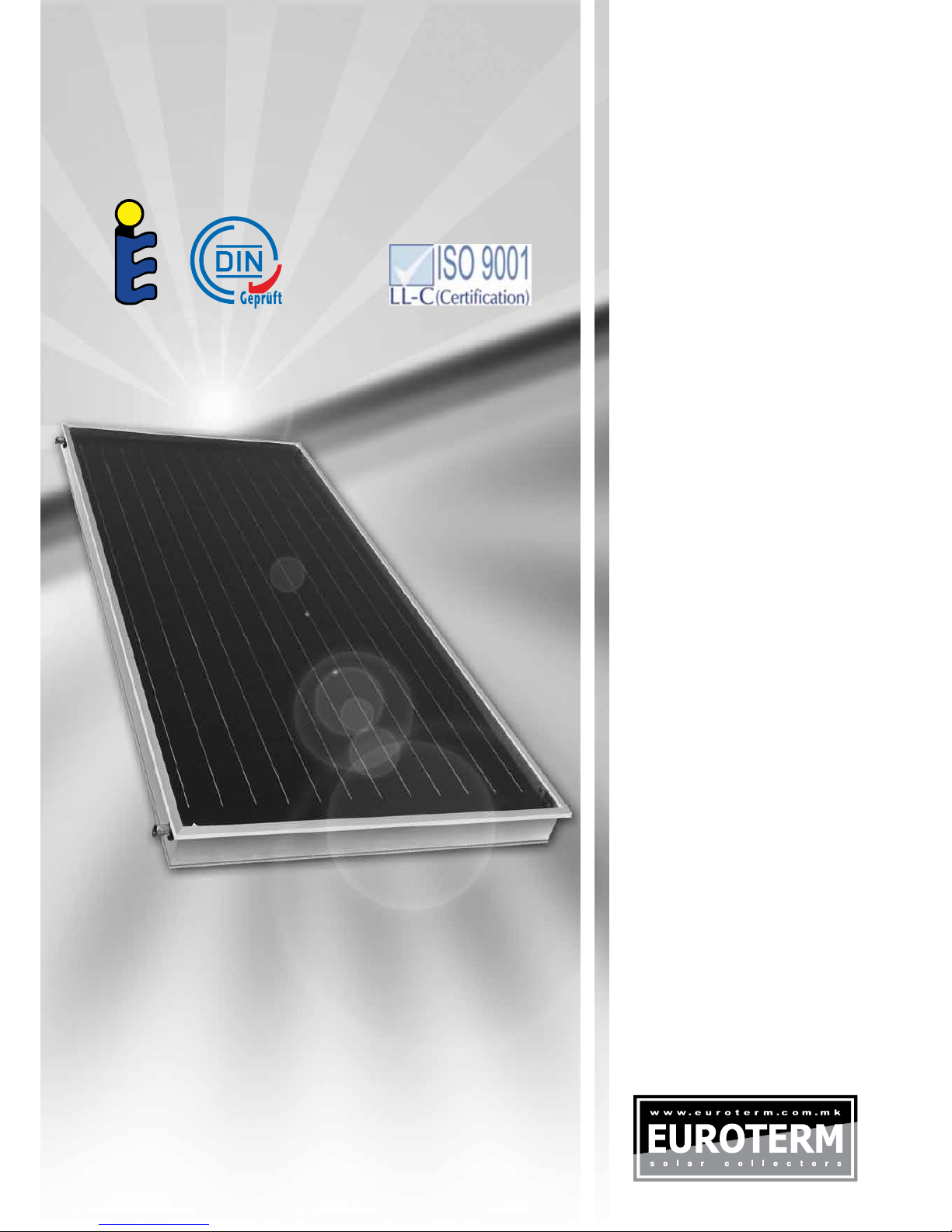
copper absorber with Eta plus selective foil
0.2 mm, corrugated
low iron tempered glass, 4 mm thick
dimensions 2149 x 1159 x 90 mm
Technical characteristics:
SELECTIVE SOLAR COLLECTOR
TYPE ESK 2.5 - SB
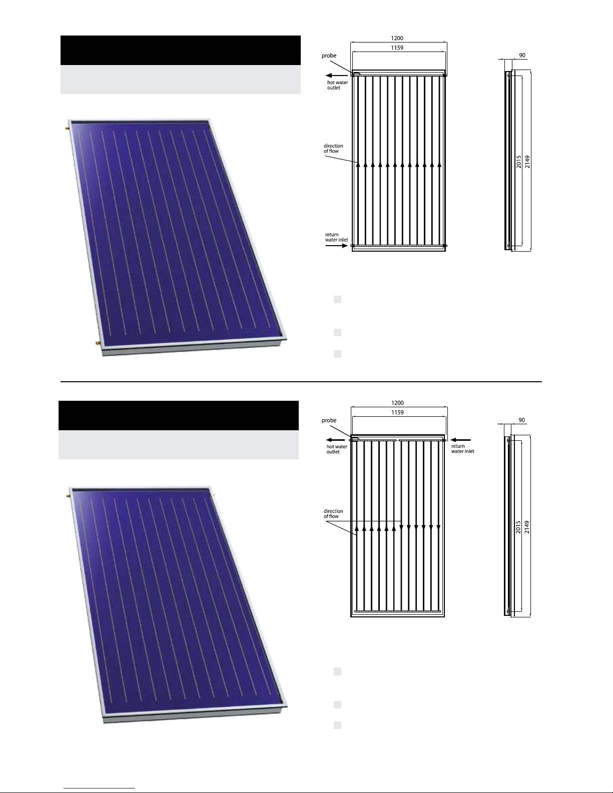
copper absorber with Eta plus selective foil
0.2 mm, corrugated
low iron tempered glass, 4 mm thick
dimensions 2149 x 1159 x 90 mm
Technical characteristics:
SELECTIVE SOLAR COLLECTOR
TYPE ESK 2.5 - SB U

ESK 2.5 SB - U
ESK 2.5 SB
Tip
Gross area
Light entering area
Absorber surface (corrugate)
Absorber material
Absorption coefficient (Eta plus)
Emission coefficient (Eta plus)
Cu Pipe register frame
Collective Cu pipe frame
Absorber volume
Transparent front cover
Solar light transmission through glass
Solar energy transmission through glass
Number of connections
Connection diameter
Max. working / test pressure
Stagnation temperature
Insulation - back side
Insulation - on the sides
Back area
Collector construction
Welding method
Height
Width
Depth
Weight
(m
2
)
(m
2
)
(m
2
)
(%)
(%)
(mm)
(mm)
(l)
(%)
(%)
(R)
(bar)
(
o
C)
(mm)
(mm)
(mm)
(kg)
copper sheet with "Eta plus" selectiv surface coating
4mm tempered solar glass - AGC
10 / 14
199
40 mm glass wool (50kg/m
3
)
-
0.5 mm embossed aluminium sheet
aluminium profil AlMgSi 0,5 F22
ultrasonic
2,49
2,35
2,32
95 ± 2
5 ± 2
Ф 8 x 0,5
Ф 22 x 0,8
1,7
92 ± 2
91 ± 2
4
Ф 22
2149
1159
90
44
2,49
2,35
2,32
95 ± 2
5 ± 2
Ф 8 x 0,5
Ф 22 x 0,8
1,7
92 ± 2
91 ± 2
2
Ф 22
2149
1159
90
44
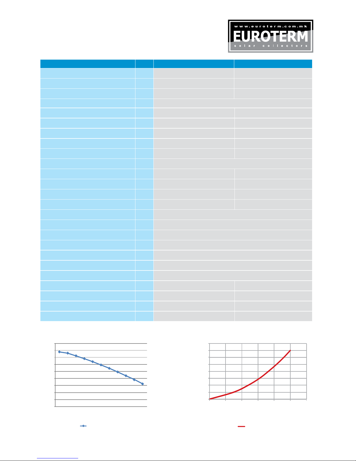
Collector eciency Pressure drop
Collector efficiency for G = 800 W/m2
0.0
0.1
0.2
0.3
0.4
0.5
0.6
0.7
0.8
0.9
1.0
0.00 0.01 0.02 0.03 0.04 0.05 0.06 0.07 0.08 0.09 0.10
Tm* [Km2/W]
Absorber
Aperture
Gross
Reference area Absorber area Aperture area Gross area
η0(-) 807.0457.0667.0
a181.454.425.4)K²m/W(
a2(W/m²K²) 0.0042 0.0041 0.0039
Pressure drop in Pa
0
200
400
600
800
1000
1200
1400
0 50 100 150 200 250 300 350 400
Flowrate [l/h]
20° C
Flow rate [l/h] 0 80 160240320400
Pressure drop [Pa] 0 1553525938771203
copper absorber with Eta plus selective foil
0.2 mm, corrugated
low iron tempered glass, 9mm lled with ar-
gon, 2 x 4 mm thick
dimensions 2149 x 1159 x 102 mm
Technical characteristics:
Technical characteristics:
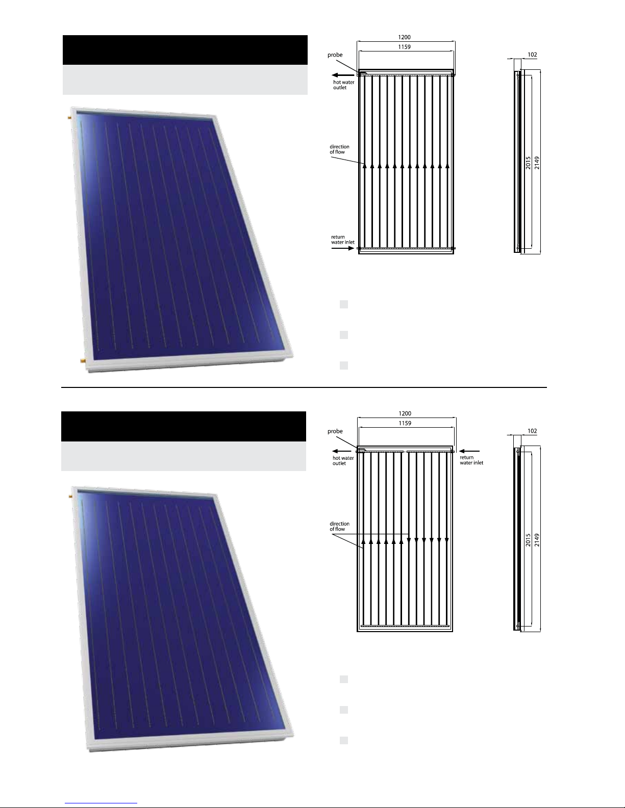
copper absorber with Eta plus selective foil
0.2 mm, corrugated
low iron tempered glass, 9mm lled with ar-
gon, 2 x 4 mm thick
dimensions 2149 x 1159 x 102 mm
SELECTIVE SOLAR COLLECTOR
TYPE ESK 2.5 - SB T
SELECTIVE SOLAR COLLECTOR
TYPE ESK 2.5 - SB TU
Tip
Gross area
Light entering area
Absorber surface (corrugate)
Absorber material
Absorption coefficient (Eta plus)
Emission coefficient (Eta plus)
Cu Pipe register frame
Collective Cu pipe frame
Absorber volume
Transparent front cover
Solar light transmission through glass
Solar energy transmission through glass
Number of connections
Connection diameter
Max. working / test pressure
Stagnation temperature
Insulation - back side
Insulation - on the sides
Back area
Collector construction
Welding method
Height
Width
Depth
Weight
(m
2
)
(m
2
)
(m
2
)
(%)
(%)
(mm)
(mm)
(l)
(%)
(%)
(R)
(bar)
(
o
C)
(mm)
(mm)
(mm)
(kg)
copper sheet with "Eta plus" selectiv surface coating
2 x 4mm tempered solar glass with 9 mm space gap, filled up with argon
10 / 14
236
12 mm elastomeric rubber foam / 40 mm glass wool (50kg/m
3
)
12 mm elastomeric rubber foam / 10 mm glass wool (50kg/m
3
)
0.5 mm embossed aluminium sheet
aluminium profil AlMgSi 0,5 F22
ultrasonic
ESK 2.5 SB T
2,49
2,22
2,20
95 ± 2
5 ± 2
Ф 8 x 0,5
Ф 22 x 0,8
1,7
96 ± 2
95 ± 2
4
Ф 22
2149
1159
102
70
2,49
2,22
2,20
95 ± 2
5 ± 2
Ф 8 x 0,5
Ф 22 x 0,8
1,7
96 ± 2
95 ± 2
2
Ф 22
2149
1159
102
70
ESK 2.5 SB - TU
0
10
20
30
40
50
60
70
80
90
5 10 20 30 40 50 60 70 80 90 100
Efficiency ( %)
Ta-Tm
Collector efficiency
Collector efficiency
0
0,05
0,1
0,15
0,2
0,25
0,3
0,35
0,4
0 0,02 0,04 0,06 0,08 0,1 0,12
Δp (kPa)
Flow (kg/s)
Pressure drop
η0 = 0,8
a1 = 3,175 W/(m²K)
a2 = 0,01 W/(m²K²)
Collector eciency Pressure drop

SAFETY INSTRUCTIONS
Installation & Transportation
Solar Collectors must be secured during transportation. You must secure the collectors from falling out of
the packaging, and from scratching each other.
• Use of a carrying strap is recommended
• Do not lift the collector by the connection ports or header tube
• Avoid impacts & vibration on the collectors as much as possible
• Please lift collector by lifting lugs (if included)
On Roof Operation
Please follow the following safety & operational guidelines when installing Solar Collectors
• Included Mounting Hardware(2 x antislip protection and 4 x side bracket) is intended for
On Roof Installations Only
• Additional Mounting Hardware is needed for Pitched Roof & Tilt Mount Installations
• You will be intervening in existing roof and roof coverings during installation
• Please ensure that proper measures are taken for protection of all installation crew
• Familiarize yourself with local laws & regulations, and follow them carefully
Important Note - Solar Collectors should not be lled when the sun is out because scalding can occur
due to steam being released from the system. If you must ll the Solar Collectors during sunny periods,
please cover the collectors.
Lightning Protection
Solar Collectors should be electrically connected to each other, and to the building’s Earth ground via the
shortest possible route. An authorized lightning protection specialist should be consulted to examine the
installation and installation site.

INSTALLATION INSTRUCTIONS
Collector Layout, Orientation, and Siting
Place the collector where it will receive the maximum amount of sunlight available in your location. Eu-
roterm ESK 2.5 SB collectors may be installed on a roof, against a south facing wall, or on the ground.
Orientation
Orientation and tilt are critical to performance. The Euroterm ESK 2.5 SB collectors should be ori-
ented (faced) as close to true south as practical, although they may be faced as much as 20° east or
west of true south with less than 5% loss in capacity.
Shading
Trees, chimneys, dormers, other buildings, new construction, and even fences may shade the collec-
tor array, especially in the winter when sun angles are low and shadows are long. Be sure the collec-
tors are placed where they will be not shaded by these obstructions. As a rule, no more than 5% of the
collector area should be shaded between the hours of 9:00 a.m. and 3:00 p.m.
To avoid shading by collectors on each other, the front to front dimension must be 2.5 times the high-
est point of the front collector.
Angle of Inclination or Tilt Angle
For domestic water, use an optimum tilt of the site’s latitude plus 5°, although the slope may be 10°
greater or less with a capacity loss of under 5% for the system. For a solar space heating system, a
steeper tilt angle is important for optimal winter performance. The steeper tilt will favor winter system
operations when the sun is low in the sky. Therefore, for space heating systems chose a tilt of latitude
plus 15°. The variation of 10° either way will not seriously affect the total annual performance of the
system, all other things being equal.
Shedding Snow
A tilt angle of 50° or more is necessary in regions of heavy snowfall and accumulation. Tilt angles of
50° and above will shed snow from OVSOL evacuated tube collectors even after severe storms. It is
critical in heavy snow areas that the collectors be sloped to at least a 50° tilt angle. If collectors are
installed on a at roof in an area which receives heavy snowfalls, the lower end of the units should
be at least 40 cm above the roof level to minimize chances of snow build-up on the bottom end of the
collectors.
Wind & Snow Load
The wind and snow loads for your location should be taken into account when installing a Euroterm
ESK 2.5 SB Flat Plate Solar Collector and calculating the overall weight-carrying capacity of the roof.
Euroterm ESK 2.5 SB Flat Plate Solar Collector Mounting Hardware is designed for:
• 1.2 kN/m2 (snow load)
• 1.1 kN/m2 (wind load)

Operation, Checks and Maintenance
The solar system offers unmanned and almost maintenance-free operation. Despite that, it is important
to check the right functioning of the system within the rst days of operation. First of all the temperature,
system pressure and pump operation shall be checked. Once a year, preferably during a sunny day,
it is necessary to check the working order and tight xing of the collectors, verify the system tightness
and pressure (incl. pressure in the expansion vessel) and the pump operation. At least once in every
2 years the heat carrying uid shall be checked for its antifrost properties. The system shall be always
replenished with the same uid as the original lling was.
INSTALLATION INSTRUCTIONS

FILLING
PREPARATION OF MIXTURE OF WATER + glycol
Glycol is supplied separately in the standard package and mixed with water in the tank before lling the
installations (for example. 40% glycol and 60% water-resistant to frost temperatures from -21 ° C).
Fill the solar system exclusively with polypropylene glycol which is intended specically for use in solar
devices. Polypropylene glycol retains its properties in the area of 32 ÷ 180 ° C.
Polypropylene glycol is biologically compatible and not toxic.
Do not ll pure glycol rst and then add water.
If the water contains a high level of chlorine is it necessary to use a distilled water .
Antifreeze temperature Density
50% -32 ° C 1.045 kg/dm3
40% -21 ° C 1037 kg/dm3
30% -13 ° C 1.029 kg/dm2
FILLING
1 - Open the valve (A)
2 - The manual venting valve at the highest point (see
drawing ) shall be open during charging
3 - Open the venting valve (7)
4 - Allow the liquid driven by external pump circulates until all air
bladders are removed. Close the manual venting valve.
5 - Raise the pressure in the installation at 4 bar.
6 - Leave the installation to work about 20 minutes
7 - Repeat the procedure from point 2, while
the air is completely dropped
8 - Adjust the pressure in the installation of 3 bar.
- Close the valve (A) and venting valves, to prevent possible
evaporation of heat transfer uid.
Do not ll the installation during full insolation and while collectors are hot.
The system must not be replenished with water.
7
A
The base plate - Tray 1 (art. 50 206), is mounted on
the roof beam using the M8 x 80 screws (art. 50 210).
Base plate (Art. 50 206), is prepared so that it is al-
ways possible to use at least three screws.
Carrier Prole - Tray 2 (art. 50 207), is placed on the
basic plate - Tray 1 (art. 50 206). Grooved carrier pro-
le and the base plate, allows removal of steps, such
as height adjustment of the screw, and thus shortens
the time of installation, as well as number of hours of
the installer on the roof.
Using self-locking screw M10 x 20 (art. 50 .210) angu-
lar prole is associated with the carrier prole - Tray 2
(art.50 207). Angular prole (art. 50 203), is an impor-
tant element in universal mounting system. It is used in
cross-mounting and it is connecting element between
the universal prole (art. 50 100) and roof hooks - Tray
2 (art. 50 207).
Universal prole (art. 50 100), is set to the angle pro-
les (art. 50 203). Fixing is done with self - locking
screw M10 x 20 (art. 50 210) and screw channels.
Screw channels are designed so that the screw can be
tightened with torque of 17 Nm.
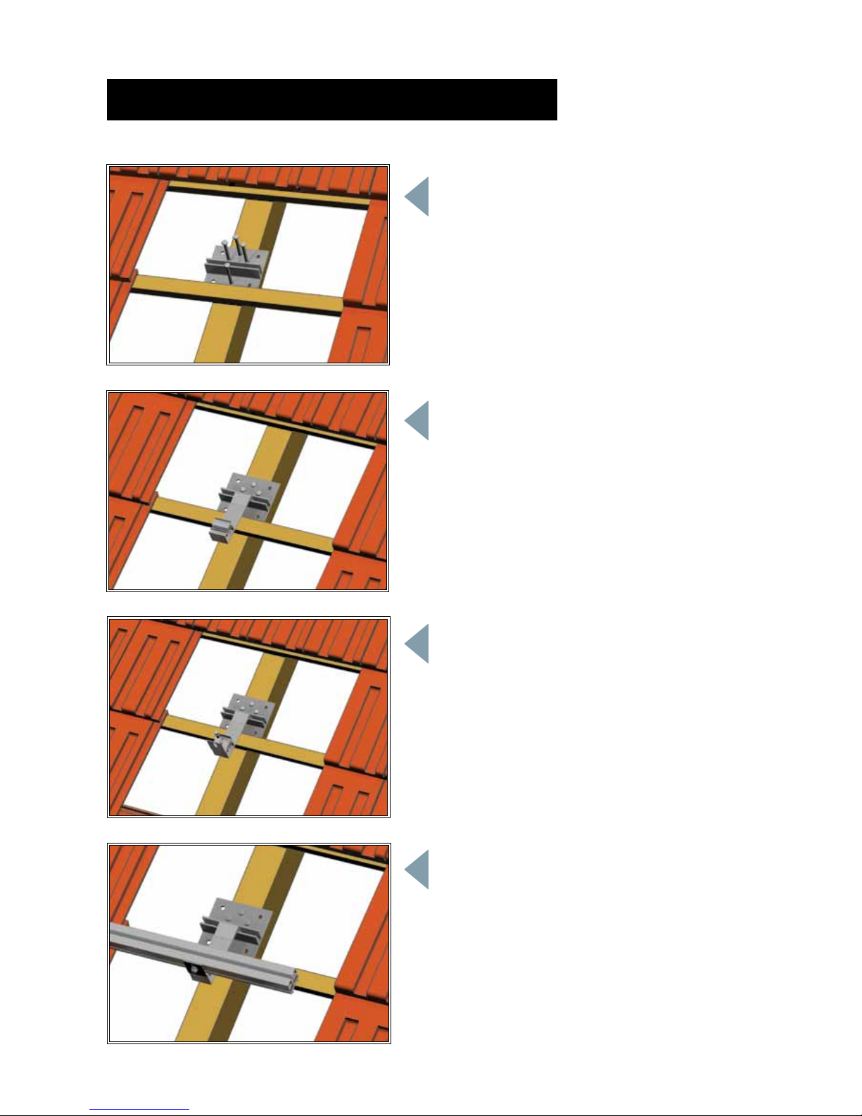
PARALLEL MOUNTING WITH THE ROOF LINE

Anti slip protection - stainless steel shafts (art. 50 215),
is placed on the lower prole for prevent sliding of the
collectors during installation.
Attaching the solar collector on a universal platform is performed using side brackets (art. 50 211).
PARALLEL MOUNTING WITH THE ROOF LINE

PARALLEL MOUNTING WITH THE ROOF LINE
On the already mounted base plate - Tray 1 (art. 50
206) and carrier prole - Tray 2 (art. 50 207), we placed
the angle prole (art. 50 203) rotated for 90 degrees,
using self - locking screw M10 x 20 (art. 50 210).
Universal proles (art. 50 100), using self-locking
screw M10 x 20 (art. 50 210) and screw channels are
placed on angular prole (art. 50 203), parallel to the
roof beams.
With angular panels - 90o (art. 50 205), universal
mounting platform is adapted for mounting under a
certain angle.
Achieving the desired angle is allowed by using varia-
ble angular plates (art. 50 204). Universal proles with
self-locking screw M10 x 20 (art. 50 210) and screw
channels are placed on the corner plates (art. 50 205)
and (art. 50 204).

PARALLEL MOUNTING WITH THE ROOF LINE
The angular proles (art. 50 203) are placed on the
universal proles (art. 50 100), using self - locking
screw M10 x 20 (art. 50 210) and screw channels.
On the angular prole (art. 50 203), which is rotated
for 90 degrees, universal proles (art. 50 100) are set
normal to the roof beams. On the lower prole of an
already mounted, universal platform, is placed antislip
protection - stainless steel shafts (art. 50 215), for pre-
vent sliding of the collectors during installation.
Attaching the solar collector on a
universal platform is performed as
well as in the parallel mounting with
the roof line.

FACADE MOUNTING
rain protection
prole
use four antislip
protection bracket

Hold rmly with the size 24 spanner and tighten the
union nut onto the cutting connection with the size 27
spanner.
Avoid applying extra torsion on the Header as you
install the connectors. Always use a spanner to x the
header and then install the connectors.
EUROTERM solar thermal collectors are interconnected throught 22 mm common joints.
Straight and corrugated stainless steel joints are recommended.
CONNECTING COLLECTORS
-
-

COLLECTOR ARRAY LAYOUT
1200
150
900 900 302
2404
max 1700
max 1700
900 900 900 454
3608
max 1700
900 900 900 900 900
156
4812
900
900 900 900 900 900 900 308
6016
max 1700max 1700
900 900 900 900 900 900 900 460
7220
max 1700
Collector eld measurement (after distance 900 mm)
Collector dimensions: 2149x1159x90 (all specied dimensions in mm)
Weight: 45 kg
Roof rafter
The base plate and carrier
prole (Tray 1 and 2)
Universal prole
This manual suits for next models
2
Table of contents
Popular Solar Panel manuals by other brands


Viessmann
Viessmann VITOSOL-F Service instructions

Viessmann
Viessmann Vitosol 300-TM Installation information

Donaldson Torit
Donaldson Torit E-100 Installation and operation manual

Panasonic
Panasonic EVERVOLT EVPV Series General installation manual

Curtech
Curtech CT-K80 user manual

oventrop
oventrop ovsol installation guide