1
Johnson Controls Metasys N2 Communications Interface
JOHNSON CONTROLS N2 TECHNOLOGY OPTION
A System Overview
The Johnson Controls N2 Technology Option provides a serial data port, allowing VSDs
(variable speed drives) to be linked to form a network. Using a Network Control Module, this
network can be continuously controlled to provide supervision and monitoring for each VSD in
the system.
With each unit under local
control, the central
supervisor performs only
periodic setpoint updating,
control sequencing and data
collection.
In the system, the Network
Control Module acts as the
Master, and the VSD as the
Slave.
The network of VSDs can
be set-up using each unit’s
MMI/Operator Station.
Protocol
This card communicates using the Johnson Controls N2 protocol. Any connections made to it
most comply with this protocol. All effort has been made to maintain compatibility with devices
using this protocol.
Product Features
•Suitable for use with:
HVAC10 Drive Products software version 4.6 onwards
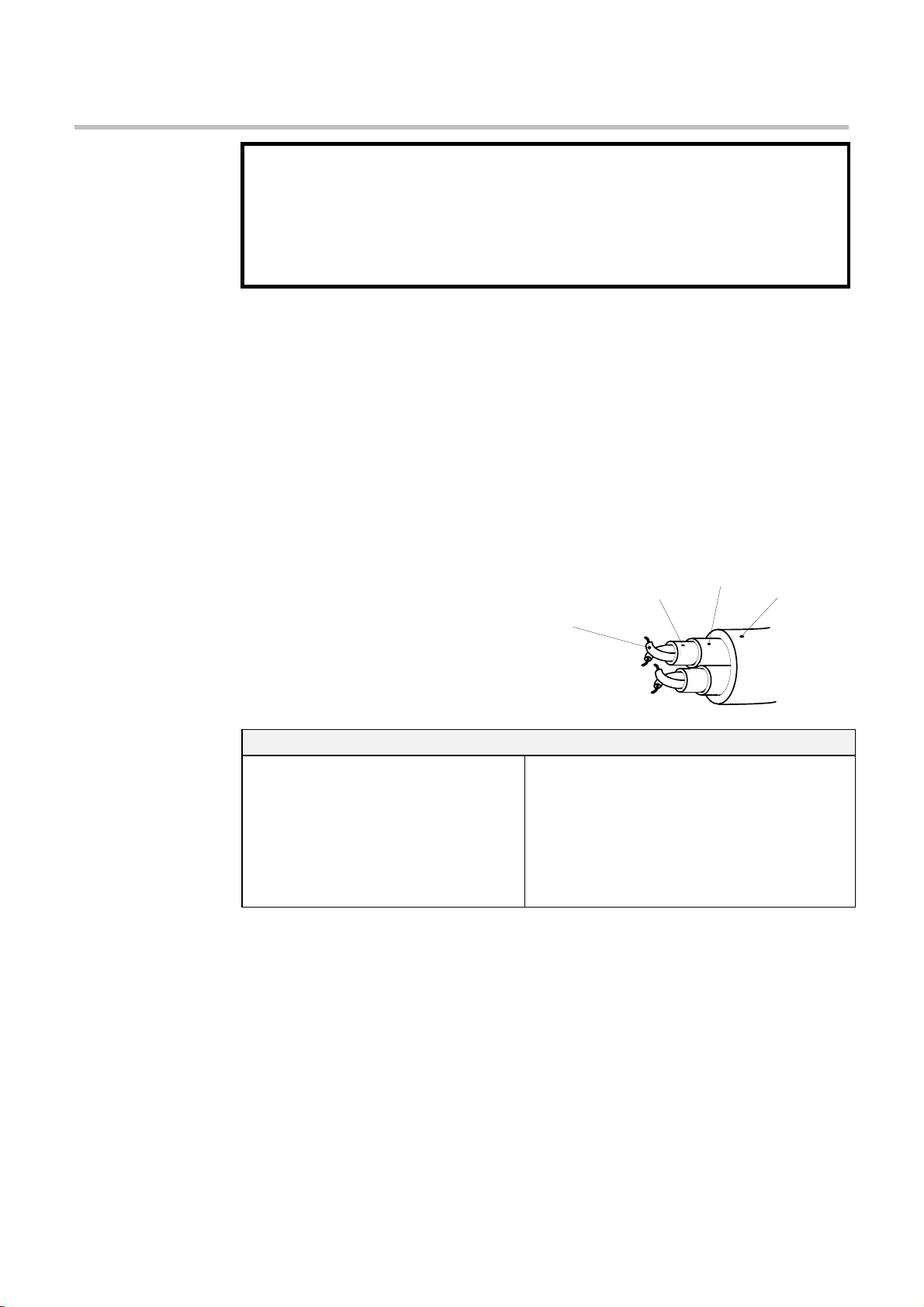
•Connection using 2-wire shielded twisted pair (RS485)
•Protocol tag access for defined N2 parameters
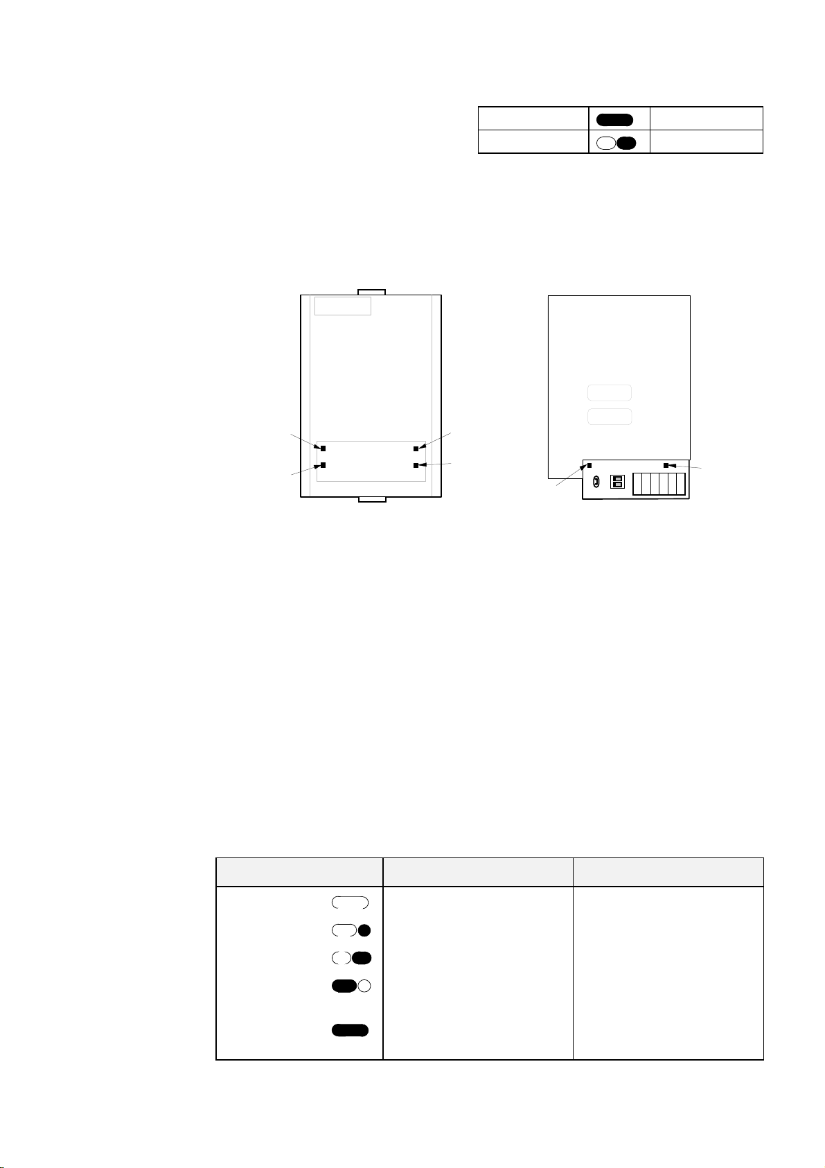
Size Notation – Part Numbers
Size 1 HVAC10 drives use the 6053-JMET Metasys N2 Technology Box.
All Size 2 and 3 HVAC10 drives use the 6055-JMET Metasys N2 Technology Box.
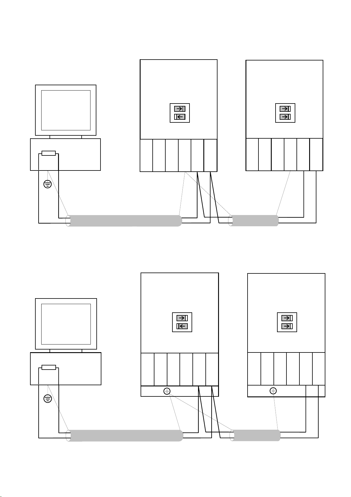
Advantages with this type of control system
1. Multi-wire analog transmission from a central programmable
controller is replaced by a bussed digital system using serial
data transmission over differential twisted-pair wires.
2. Digital transmission is fundamentally less noise-prone than
analog methods, and the accuracy of the transmitted data is
unaffected by the transmission medium. The use of intelligent
devices at either end of the data link allows error checking to
be used. This virtually eliminates the effects of electrical noise
on data integrity. It is therefore possible to issue setpoints to
drives with much higher accuracy using this method.
3. The communication standard used allows up to 32 drives to be
connected to a single link which can be driven from a
computer serial port.
4. The chosen standard and protocol are compatible with other
Eurotherm Group products. Temperature controls, process
controls, data loggers and drives can communicate easily with
a common supervisory system.
This manual was downloaded on www.sdsdrives.com