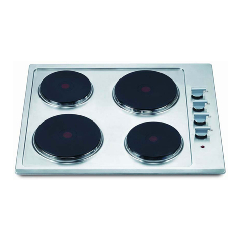
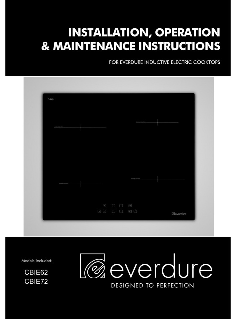
Everdure CBEE61 Manual

DESIGNED TO PERFECTION
INSTALLATION, OPERATION
& MAINTENANCE INSTRUCTIONS
FOR EVERDURE VITROCERAMIC ELECTRIC COOKTOPS
Models Included:
OBES61 INSTALLATION, OPERATION AND MAINTENANCE INSTRUCTIONS
FOR EVERDURE BUILT-IN ELECTRIC OVEN RANGE
OBES61, OBES62 & OBES63 BUILT-IN ELECTRIC OVENS
CBEE61

DESIGNED TO PERFECTION
INSTALLATION, OPERATION AND MAINTENANCE INSTRUCTIONS
FOR EVERDURE BUILT-IN ELECTRIC COOKTOP RANGE
CBEE61 VITROCERAMIC ELECTRIC COOKTOP
CONTENTS
SECTION PAGE NO.
Important Safety Instructions ………….. 3
Appliance Details ………………………… 4
Electrical Connections ………………..…. 5
Installation ………………………………… 6-7
Operating Instructions …………………… 8-11
Cleaning ………………………………….. 11
It is important that you retain these instructions, proof of purchase as well as
other important documents about this product for future reference.
2

DESIGNED TO PERFECTION
IMPORTANT SAFETY INSTRUCTIONS
IMPORTANT: Read the assembly instruction section and safety precautions of this booklet carefully
before removing the contents of this carton.
1. This appliance is not intended for use by persons (including children) with reduced physical, sensory or mental capabilities, or
lack of experience or knowledge, unless they have been given supervision or instruction concerning the use of the appliance by
a person responsible for their safety. Children should be supervised to insure that they do not play with the appliance.
2. After removing the packaging, make sure to check if there is any damage to the appliance. If there is any damage, never
attempt to use the appliance and immediately contact your Authorized Service Centre, as packaging materials need to be
collected immediately and put out of reach.
3. In certain circumstances electrical appliances may be a danger hazard. Check the conformity of voltage and power settings,
which are specified on the information plate attached to the appliance and/or packaging, with the usage conditions available.
4. Do not place heavy objects in or on these appliances, use for storage or as a cutting surface. This appliance is designed for
cooking food only. Use flat based, stable cooking pots only.
5. This appliance is designed for domestic household use only and for the cooking of domestic food products. Use as a commercial
appliance will void the warranty. It should not to be used in a marine environment or outdoors and must be fully built in. Do not
use the appliances until fully installed.
6. A means for disconnection must be incorporated in the fixed wiring in accordance with the wiring rules.
7. The electrical connection must be accessible after installation. The appliance must be electrically isolated before any maintenance
can be performed.
8. The appliance is not intended to be operated by means of an external timer or separate remote control system.
9. Electrical connection must be made as per local wiring rules and regulations. Do not disconnect the appliance with wet hands or
bare feet, and do not disconnect the power cord with extreme force.
10. Ensure that the kitchen is well ventilated or mechanical ventilation is in use while cooking on this appliance.
11. Do not store or use flammable materials or aerosols near the cooktop. Items made from aluminium, plastic or plastic film should
also be kept away from the appliance, as they may fuse to the surface.
12. WARNING – The surface temperature of this appliance exceeds 95°C. To avoid a hazard, under bench access must be restricted.
A board must be installed underneath the cooktop.
13. WARNING - The cooktop will become hot during and directly after use. Do not touch the surface during this time, as it may be hot
and can cause burns. To avoid burns, children should be kept away.
14. Cleaning may only be commenced on the appliance once it has cooled down and is turned off. Do not use a steam jet or any
other high pressure cleaning equipment to clean the appliance.
15. When the appliance is not being used, turn the appliance off.
16. Where this appliance is installed in a caravan, it shall NOT be used as a space heater.
17. Do not modify this appliance.
18. Do not use harsh abrasive cleaners or sharp metal scrapers to clean the glass surface as they can scratch the surface, which may
result in the glass shattering. Clean the glass using a warm damp cloth (e.g. dishcloth) and dry it with a soft dry tea towel.
19. All cabinetry and materials used in the installation must be able to withstand a minimum temperature of 50°C above the ambient
temperature of the room it is located in, whilst in use. Certain types of vinyl or laminate kitchen furniture are particularly prone to
heat damage or discolouration at temperatures below the guidelines given above. Any damage caused by the appliance being
installed without adhering to the temperature limits set out above will be the liability of the owner. To avoid any hazards, limit
access to the under-bench section of the cooktop.
20. The appliance must be installed and put into operation by an authorised technician under the conditions provided by the
manufacturer in this manual. The manufacturer cannot be held responsible for any damage that might occur due to faulty
installation.
21. Damage can occur to bench tops if pots and pans are allowed to overlap the bench top. This can result in heat being transferred
to the bench top. Ensure that correct sized pots & pans are used. Cast iron and cast aluminium cookware with damaged bases
may scratch the cooktop surface if they are dragged across it. Pans should be lifted on and off the cooktop surface and not
dragged. Cooking zones should not be switched on without cookware placed on it. Also the cookware should not be empty for any
length of time.
22. If any cracking is noticed on the vitroceramic cooktop, turn the appliance off immediately and call your Authorised Service Centre.
23. Do not leave the cooktop while cooking with solid or liquid oils. There may be flaming up in conditions of extreme heating. Never
pour water onto the flames occurring from oil. Immediately turn the cooktop off and cover the pan with a lid or fire blanket in
order to smother the flame.
3
3

DESIGNED TO PERFECTION
APPLIANCE DETAILS
ELECTRICAL DETAILS:
COOKTOPS:
Rated Voltage: 220-240Vac 50Hz
CBEE61 - 5900W
COOKTOP–Directlywired to mains supply
This information can be found on the rating plate (identification plate) affixed to the underside of the
appliance.
SIZES:
Relevant Sizes: LENGTH (mm) WIDTH (mm) HEIGHT (mm)
Cooktop Size 590 520 45
Cut-out Size 560 490 -
4

DESIGNED TO PERFECTION
ELECTRICAL CONNECTIONS
LOCAL AUTHORITY REQUIREMENTS
Installation is only permitted by a licensed electrician, and carried out according to instructions
provided by the manufacturer. Incorrect installation might cause harm and damage, for which the
manufacturer accepts no responsibility.
ELECTRICAL INSTALLATION
Before carrying out the connection to the power supply, the voltage rating of the appliance (stamped on the
appliance identification plate) must be checked for correspondence to the available mains supply voltage, and
the mains electric wiring should be capable of handling the oven’s power rating (also indicated on the
identification plate). If you have any doubts, call in a qualified technician.
NOTE: For connections to the mains power supply, never use adapters, reductions or multiple power points as
these may overheat and catch fire. Do not install separate timers.
After having installed the appliance, the switched outlet must always be in an accessible position.
The electrical safety of this appliance can only be guaranteed if the cooktop is correctly and efficiently earthed,
always ensure that the earthing is efficient; if you have any doubts call in a licensed electrician to check the
system. The manufacturer declines all responsibility for damage resulting from an installation which has not
been correctly earthed.
WARNING: If any damage occurs to the power cable during or after installation, it must be replaced
immediately by a licensed electrician with a replacement cable from your Service Centre.
The cooktops are to be connected to a single phase 220-240Vac 50 Hz supply.
They are earthed via the cable.
The mains terminal block is located on the underside of the cooktop and the
terminals are accessible by removing the terminal block cover by removing the
cover screw. Connect the appliance as shown in the diagram to the right.
The appliance is designed for fixed connection to the mains. During
installation, an all pole disconnector should be included inside they supply
circuit with a contact opening of at least 3mm (rated 32A, delay functioning
type). The power supply cord must not touch against any hot surfaces and must
be placed so that its temperature does not exceed 75 °C at any point along its
length.
IMPORTANT: The appliance must NOT be connected to the mains supply by
means of a 10A or 15A plug and socket.
5

DESIGNED TO PERFECTION
INSTALLATION
The adjacent furniture must be able to withstand a minimum temperature rise of 50°C above the
ambient temperature of the room it is located in, during periods of use. The power supply to the
appliance must be cut off before any adjustments or maintenance work is done on it.
PREPARATION FOR INSTALLATION AND USE
Manufactured with best quality parts and materials, this modern, functional and practical cooktop will meet
your needs in all respects. Make sure to read the manual to obtain successful results so as not to experience
any problems in the future. The information given below contains rules that are necessary for correct
positioning and service operations. They should be read without fail, especially by the technician who will
position the appliance.
CHOOSING A LOCATION FOR THE APPLIANCE
There are several points to pay attention to when choosing a location for your cooktop. Make sure to take
into account our recommendations below in order to prevent any problems and dangerous situations, which
might occur later!
When choosing a location for the cooktop, attention should be paid that there are no flammable or
combustible materials in the close vicinity, such as curtains, oil, cloth etc. which quickly catch fire.
Furniture surrounding the cooktop must be made of materials resistant to temperatures above 50 C°.
Required changes to wall cabinets and exhaust fans above a built-in cooktop as well as minimum heights
from the oven board are shown in Figure 1. Accordingly, the exhaust fan should be at a minimum height of
65 cm from the cooktop. If there is no exhaust fan the height should not be less than 70 cm.
6

DESIGNED TO PERFECTION
INSTALLATION OF BUILT IN COOKTOP
In order to prevent leakage of any liquids on the counter, a special sealing tape is supplied together with
your oven. Apply this seal around the bottom edge of the cooktop (see below). The brackets are installed to
hold the cooktop in place.
Cut out a hole in the bench top as shown below. Place the cooktop (controls to the right) in the hole and fix in
position using he brackets.
The bottom of the cooktop reaches temperatures above 95°C. A board must be placed a minimum of
130mm below the cooktop that prevents anyone from touching the underside of the cooktop.
7

DESIGNED TO PERFECTION
OPERATING INSTRUCTIONS
The basic layout of the cooktop is shown in the diagram below.
The cooktop appliance is operated by touching buttons, with the functions confirmed by LED displays and
acoustic signals.
Turning On and Turning Off the Cooktop Appliance
If the appliance is in
Stand-By-Mode,
it is put into
Operating-Mode
by pressing the
On/Off
button for at least 1
second. A beep signal indicates the successful operation acoustically.
On all Heat Level Displays a ´0` will appear and all
Decimal Points
of the Heat Level displays will flash (1
second on, 1 second off).
If there is no operation within 10 seconds, all the Heat Level Displays will automatically turn off. If the displays
are turned off, the hotplates will be re-set into
Stand-By-Mode
.
If is pressed more than 2 seconds (in
Operating-Mode
), the appliance is switched off and is set into the
S-
Mode
again. The appliance can be turned off by pressing at any time; even if other buttons are pressed
simultaneously.
If there is a residual heat of a hotplate remaining, this will be indicated in the correspondent heat setting Heat
Level
Display as a red “H”
.
8

DESIGNED TO PERFECTION
Selecting A Hotplate
If a single hotplate is chosen with the corresponding
Active/Deactivate Hotplate Button
, the
Decimal Point
of
the chosen hotplate flashes. For the selected hotplate, you can set or adjust the heat level between 1-9 by
touching the
Heat Setting Buttons
or . All of the other hotplates will have a visible ‘O’ or ‘H’ (if recently
used) but they will not have a decimal point.
Any chosen hotplate will automatically start at heat level 5 and can be changed using the Heat Setting Buttons.
If left idle the decimal point on the chosen hotplate will turn off and the Heat Setting Buttons will no longer
operate that chosen hotplate unless that hotplate is chosen again with the Activate/Deactivate hotplate button.
The Heat Level Display works on a thermostat system. This means that the hotplate will switch on and off
(radiating red when on) in order to remain at the chosen Heat Level. NOTE the hotplate will remain on for
longer periods if a higher Heat Level is chosen, alternatively the hotplate will be on less regularly on lower Heat
Level Settings.
Turning On The Dual Zone Hotplate
The activation of the dual zone hotplate is done after pressing the duel zone hotplate button . This is
confirmed by a beep signal. At the same time, the corresponding
Dual Zone Hotplate Indicator
goes on
statically. Touching
for a second time makes the status of the dual zone toggle, changing it from dual
zone on to dual zone off and back again).
NOTE: The extension zone can be activated only after a level between 1-9 is set on the basic zone of the
specific hotplate.
Setting The Cooking Level With and Without Heat Boost
Every cooktop is equipped with heat boost functionality.
If the heat boost is active, then the cooktop hotplate will be using maximum power for the period of the heat
boost time, which is dependent on the selected heat setting. This is indicated through a flashing ´A`,
alternating with the heat setting value (e.g. 0.5 sec “A“ and 0.5 sec “9“) in the Heat Level Display. The heat
setting will be indicated only after the heat boost time has ended.
When a hotplate is activated, pressing in the cooking level 9 position activates the heat booster. Upon
setting the heat boost setting, an ´A` will be indicated alternately with the heat level chosen (e.g. 9 - Means
level 9 and heat boost are active now).
The heat boost can be turned off by pressing until the Heat Level Display appears as “0“. If the heat boost
should be used, it can always be activated by pressing again if the heat setting is set to level 9.
Turning Off Individual Hotplates
A particular hotplate can be turned off in 2 different ways:
· Simultaneous operation of and buttons.
· Reduction of the heat setting to “0“ by operating the button.
Simultaneous operation of and buttons
The required hotplate must be chosen with the
Active/Deactivate Heater Button
, the
Decimal Point
of the
related
Heat Level Display
flashes. To turn off the hotplate, and must be pressed at the same time. A
beep signal sounds and “0“ appears in the Heat Level Display.
An assigned
Dual Zone Selection
button
also disappears if it is active. If there is a residual heat from this
hotplate remaining, this will be indicated by a static display of a red ´H` in the Heat Level Display area.
Reduction of the heat setting to ´0` by operating button
The hotplate can also be turned off by reducing the operated heat setting to “0“. When the
Heat Level Display
indicates “0“, the associated
Decimal Point
of the hotplate will also be turned off. If there is a residual heat
from this hotplate remaining, this will be indicated by a static display of a red ´H` in the Heat Level Display
area. 9
9

DESIGNED TO PERFECTION
Key Lock
The key lock functionality is for blocking and setting the appliance into a locked mode during operation. Touch
modifications (e.g. increase heat settings) and others will not be possible. It is only possible to switch the
appliance off.
The lock function is activated if
Key Lock
is pressed for at least 2 seconds. This operation is acknowledged
with an audible beep. Once successful, the
Key Lock Indicator
flashes and the cooktop is locked. The cooktop
can only be locked when in
Operating Mode
.
If the cooktop is locked, only can be operated and all other buttons are blocked. If any other button is
touched while in the locked mode, the beeping signal sounds and the
Key Lock Indicator
flashes as indication
for the activated key lock functionality. Once switched off, the appliance can not be restarted again without
unlocking first.
After pressing for 2 seconds, the
Key Lock Indicator
disappears. This unlocks the cooktop controls so it can
be operated normally.
TOUCH CONTROL SAFETY FUNCTIONS
The following safety functions are available to avoid unintended operations of the cooktop control:
Hotplate Safety Cut Off
To prevent the appliance from unwanted, random button operation, a sensor monitoring is included.
In the case of one or more buttons being pressed longer than 12 seconds, the sensor monitoring routine
indicates acoustically that an “error” (pot or other object placed on the button, sensor failure, etc.) has occurred
and switches off the appliance.
If residual heat is present, it will be displayed in all other Heat Level Displays with a red “H”.
Over Temperature Switch Off
Because the controls are very close to the hotplates on the right side of the cooktop, it is possible that a pot can
be placed half on the control and not sensed by the sensor safety cut off (not covering a sensor). This can
cause the cooktop to heat up to a very high temperature, which makes the glass and the buttons untouchable
without burning a finger.
To prevent the cooktop control unit from damage caused by overheating, a temperature sensor is available on
the touch control unit which will turn the appliance off when overheating occurs.
Operating Time Limitation
The cooktop control has a limitation on the operating time. If the heat setting for a hotplate has not been
changed for a certain time, then the hotplate will turn off automatically (a “0“ is displayed for 10 seconds, then
the residual heat sign “H” is displayed). The limit of the operating time depends on the selected heat setting.
After an automatic turn off of a hotplate (as described above) the hotplate is operable again and the maximum
operating time for this heat setting is re-applied.
Residual Heat Functions
After all cooking processes there is some heat stored in the vitroceramic glass called residual heat. The control
can calculate roughly how hot the glass is in the worst case. If the calculated temperature is higher than + 60 °
C, then this will be indicated in the corresponding Heat Level Display after the hotplate control has turned off
with a red “H”. The residual heat display is shown as long as the calculated heater temperature is > + 60 ° C.
The display of the residual heat has the lowest priority and is overwritten by every other display value, during
safety turn offs and the display of an error code.
When the supply voltage is re-applied to the cooktop after an interruption to the supply voltage, the residual
heat display flashes if the corresponding hotplate had a residual heat of greater + 60 ° C before the power
interruption occurred. The display will flash until the maximum residual heat time has expired or the hotplate
has been selected and activated.
10
10

DESIGNED TO PERFECTION
CLEANING
NOTE: Cleaning and maintenance operations must only be carried out when the oven is cool
(all residual heat indicators are off).
The appliance should be disconnected from the power outlet or turned off at your isolation
switch before commencing any cleaning process.
CLEANING THE COOKTOP
Cookware with rough bases should not be used as they can scratch the glass ceramic surface. The base of
the good cookware should be as thick and flat as possible. Before use, make sure that cookware bases are
clean and dry.
Always place the cookware on the cooking zone before it is switched on. If possible, always place the lids on
the cookware. The base of any cookware used must not be smaller or larger than the cooking zones; they
should be the proper size as indicated below, so as not to waste energy.
Before cleaning the cooktop, first isolate the cooktop from the power. Once done, ensure that there is no
residual heat stored in the appliance. Vitroceramic glass is very resistant to high temperature and
overheating. If there is residual heat stored in the appliance, the related residual heat indicator lamp will be
on. In order to avoid burns, let the appliance cool down.
Remove all spilt food and fat with a clean damp, warm, slightly soapy, dishcloth. Rinse cloth and wipe
cooktop again until clean, then wipe the cooktop dry with a clean tea towel or dry soft cloth.
If aluminium foil or plastic items are accidentally melted on the vitroceramic surface, they should be
immediately removed from the hot cooking area with a scraper specifically for vitroceramic glass. This will
avoid any possible damage to the surface. This also applies to sugar or food containing sugar that may be
spilled on the cooktop.
In the event of other food melted on the cooktop surface, remove the dirt when the appliance has cooled
down. Use cleaner for glass ceramic or stainless steel when cleaning the surface.
Do not use abrasive sponges to clean the vitroceramic surface. These materials may damage the surface.
Do not use chemical detergents, sprays or spot removers on the vitroceramic surface. These materials may
cause fire or the vitroceramic colour to fade. Clean with a damp, warm, slightly soapy, dishcloth.
WARNING: Using cookware that is too large can cause discolouration or damage to the cooktop surface
around the heat zones, which is NOT covered under warranty
11
11

DESIGNED TO PERFECTION
A division of Shriro Australia Pty Ltd
23-27 Chaplin Drive Lane Cove NSW 2066
1300 766 066
www.everdurekitchen.com.au
IM Ref: CBEE61 12/2009/03FC
FOR INDOOR USE ONLY
Table of contents
Other Everdure Cooktop manuals
Popular Cooktop manuals by other brands

Häfele
Häfele HH-VR603T Instructions for use and installation

Frigidaire
Frigidaire GLEFS77CSA Wiring diagram

KitchenAid
KitchenAid KGCP467HSS0 parts list

KitchenAid
KitchenAid KICU500XSS installation instructions

GE
GE Profile PP945SMSS Dimensions and installation information

KitchenAid
KitchenAid KECS100 Use and care guide