manuals.online logo
Brands
  1. Home
  2. •
  3. Brands
  4. •
  5. Missouri Wind and Solar
  6. •
  7. Wind Turbine
  8. •
  9. Missouri Wind and Solar Freedom User manual

Missouri Wind and Solar Freedom User manual

Last Revised 06/21/2018 Copyright © Missouri Wind and Solar, LLC 2017 pg. 1
Missouri Wind and Solar
Wind Turbine Manual
Introduction
1. Thank you for purchasing a Missouri Wind and Solar wind turbine system. Please be sure to fully read
and understand these instructions before installation.
2. Freedom turbines are available in 1600 watt and 2000 watt models in the following voltages: 12V, 24V,
48V. Ensure you have the right turbine by looking on the electrical wiring (“pigtail”) of the turbine for a
colored dot: green dot = 12V; no dot/“black” = 24V; grey dot = 48V.
3. DANGER! Turbines output lethal voltage and current levels. Exercise safety precautions.
Tower Considerations
1. An ideal tower is one that allows easy access to the turbine for inspection and periodic maintenance.
Common tower designs include a hinge plate at the bottom, which allows the tower to be laid down on
the ground. If you choose to use a steel pipe, we recommend several runs of guyed wire to secure the
tower.
2. Ensure the tower is 30 feet higher than the nearest obstruction (trees, buildings) in a 100’ radius.
Doubling the tower height increases power output by 34% or more. Lower heights may produce less
power. This is a function of naturally occurring winds, not the turbine’s performance. However, lower
towers may make more sense cost-wise.
3. For towers 60 feet in height, use a minimum of 3/16 inch guy wire cable to support the top of the pole
and 1/8 inch to support the middle and/or bottom. 7x7 cable –7 bundles, made up of 7 individual
wires each, twisted together into one rope - is recommended.
4. Wind turbulence will severely reduce power output and is usually caused by structures interrupting
and/or blocking clean wind from contacting the blades and tail assembly. This is evident by erratic left-
to-right pivoting of the turbine, sometimes with heavy vibrations.
5. Placing your turbine in a low wind area, or a bad location such as a rooftop or behind a building, may
still produce power, but at a much lower charging rate. Turbines mounted on rooftops or connected to
the end of a building will see considerably less output due to turbulent or “dirty” wind. The higher the
better!
6. It is recommended to drive a ground stake at the base of the tower and clamp a 4 gauge wire from the
stake to the tower pole. Grounding a battery system is typically done between only the battery
negative terminal and a ground stake.
Use 4 gauge wire for the ground. Try not to have sharp bends in the ground wires as lightning can jump
out of sharp bends. This is minimal information. Please refer to additional sources for further
grounding information.
Last Revised 06/21/2018 Copyright © Missouri Wind and Solar, LLC 2017 pg. 2
Blade and Hub Assembly
1. Raptor Generation 4 & 5 blades have a flat face near the blade tip. The flat surface must face the wind.
Correctly installed Gen 4 blades will reveal the word “Raptor” on the blade base (see Figure 1).
Correctly installed Gen 5 blades will have a notch on the blade base situated on the right side (see
Figure 2).
2. The blade bolts are designed to fit tightly. You can re-drill the blade mounting holes using a 1/4” drill
bit, if needed. If the holes are grossly off-centered, then seek a replacement before installation.
3. Use the provided self-locking nuts, and ensure the nut is seated completely against the hub (see Figure
3). Torque the blade bolt/nuts to the specifications in the list below after nut is fully seated. Do not
overtighten the nuts, as the blades may crack. Failure to adhere to this warning could result in blades
coming loose during operation, and possibly causing injury, damage, or death.
•Raptor Generation 4 (G4) Blades: 7 ftlbs
•Raptor Generation 5 (G5) Blades: 10 ftlbs
•Falcon Blades: 15 ftlbs
Figure 3
4. The blades are semi-flexible and may be slightly bent forward, backward, or out of line. The blade will
self-straighten over time and remain straight permanently.
5. These blades turn very fast and can cause severe bodily harm. Never place a wind turbine near power
lines or structures. Moving structures such as trees sway and grow and can come in contact with the
blades, causing damage or loosening or separation of the blades from the hub. Place blades high
Figure 2
Figure 1
Last Revised 06/21/2018 Copyright © Missouri Wind and Solar, LLC 2017 pg. 3
enough out of reach of children or inexperienced people. Missouri Wind and Solar, LLC assumes no
liability for injury or damage caused by these blades.
6. Inspect your blades and hub mounting fasteners annually for damage, corrosion, and tightness,
especially in humid or salty environments. Our blades require no initial or follow-up surface coating. Do
not paint the blades; UV protectant protects the blades.
7. Please allow approx. 100 hours of bearing “break in” time. Until then, turbine start up may be slow.
Turbine Wiring
1. The Permanent Magnet Generator (PMG) outputs 3-phase wild AC power. The PMG’s internal wiring
connects to a 3-wire bundle (wire size depends on PMG amps and distance between PMG and bridge
rectifier), which travels down the tower to the turbine brake, then to the bridge rectifier. The rectifier
converts 3-phase wild AC to DC, and its DC output is sent to the divert (charge) controller, then on to
the batteries.
NOTE: The PMG’s AC output is 3 hot wires. The PMG cannot be wired directly into a standard household fuse
box/service panel with power supplied by the electrical grid or generator. Doing so can result in electrical
shock, fire, even death. The PMG must be connected to an AC-to-DC rectifier.
2. Do not use solid wire or undersized wire in any leg of your turbine installation. Solid wire will not twist
and flex. Undersized wire acts as a resistor, decreasing current flow and allowing heat build-up, both of
which will reduce the turbine's power output and cause turbine failure. Proper wire selection is based
on amps and distance (refer to DC wiring chart). Wire larger than recommended is acceptable. Use
appropriate electrical connectors and heat shrink. Make clean and tight electrical connections.
Moderately tug at your connections to check for loose fittings.
Turbine Accessory Assembly
Turbine Brake Switch
1. The brake is an optional component in a turbine system, but important in that it secures the blades
from turning when raising/lowering the tower.
2. The brake is the first component to receive the 3-phase AC output of the turbine. Usually mounted
near the bridge rectifier and divert controller, to minimize length of DC cabling.
3. The brake switch has 3 black wires and 3 red wires. Connect black wires to the turbine's AC output;
connect the red wires to the bridge rectifier. Keep switch in either the “run” or “brake” position,
never let the turbine free spin. The only exception is if the fuse or breaker blows. It is better to
allow a free spin than to burn out the generator head.
NOTE: Avoid braking your turbine in winds greater than 20 MPH. Braking in these conditions can cause the
turbine stator to overheat and burn up. The brake is normally used during maintenance and turbine/tower
erection or takedown. Never allow the turbine to free-spin in high winds, as the blades can self-destruct and
open turbine voltages can be lethal and damaging to the turbine at high RPMs. It is best to leave the brake in
the “On” position and let the divert controller and diversion load regulate the turbine.
Bridge Rectifier (Figures 6 & 7)
Refer to the included rectifier instruction sheet for more detailed information.
Last Revised 06/21/2018 Copyright © Missouri Wind and Solar, LLC 2017 pg. 4
1. The rectifier will get warm during normal operation, so it is mandatory to mount the rectifier onto
a metal surface for heat dissipation. Aluminum makes the best heat sink, the larger the better.
2. The rectifier is normally mounted below the brake switch, so the 3 red wires from the brake have a
straight run to the rectifier. Make sure the rectifier positive and negative terminals are connected
correctly by looking for the + and - symbols. Do not reverse the connections.
3. Use 3/8” female spade terminals for the AC wires, or terminal lugs with a #8 screw for 90 amp
rectifier or #5 screw for 50 amp rectifiers to attach to the rectifier's metal tabs. A mechanical joint
that is also soldered will last a long time and provide superior electrical conductivity. If you do not
solder the connection, we recommend dielectric grease.
*Do not overheat the rectifier during soldering, allow no more two seconds per terminal maximum.
4. Inspect all connections on the bridge rectifier and ensure they are not coming in contact with the
rectifier housing which is conductive aluminum. This will cause serious issues and possible burn up.
5. Always place an inline fuse or breaker directly after the rectifier on the positive DC side.
Freedom II fuse sizes: 12V –120A; 24V –80A; 48V –40A
Freedom I fuse sizes: 12V –100A; 24V –60A; 48V –30A
NOTE: All electrical components may become warm or even hot. Do not install directly on or around
flammable material, such as foam insulation boards or near stored gasoline cans or other flammable
liquids. Installations should be out of reach of children and pets.
*Allow 10 inches of space around components, especially a dump load.
Diversion (Dump) Load
1. Normally mounted adjacent to the divert controller.
2. Install the divert load as per its instructions, unless it conflicts with another set of instructions such
as your charge controller instructions. Keep in mind, your diversion load relay is limited to 120
amps maximum.
NOTE: Diversion load resistors can get VERY HOT and dissipate excessive heat, especially during high
winds when continuous dumping of energy can occur. NEVER place anything flammable near the dump
load. Remove all packing material from the unit and always mount resistors on a fire-proof surface.
Divert Controller (“Charge Controller”)
1. Mount divert controller out of the weather, near the battery bank.
2. Allow room adjacent to the divert controller to mount the diversion load. Space adjacent
components several inches from the divert controller or install a heat proof barrier.
Wiring
1. Proper wire size is critical for system operation and safety. Use our DC wire chart to select the correct
wire size for your installation.
Figure 6 –90A for 12 & 24V PMGs
Figure 7 –50A for 48V PMGs
Last Revised 06/21/2018 Copyright © Missouri Wind and Solar, LLC 2017 pg. 5
NOTE: 66A also represents the maximum circuit breaker/fuse protection required. For systems
required to comply with the National Electrical Code, multiply 66A by 1.56. See the Midnite Solar DC
breakers at www.mwands.com for 0-150V DC systems.
a. Assuming the total distance between the first DC component (bridge rectifier) and the last DC
component (battery bank) is less than 15 feet, then #4 AWG DC wire is sufficient. DC wiring will be
used between the following components:
1) Rectifier to divert controller
2) Divert controller to diversion load
3) Divert controller to battery bank
Turbine Assembly
1. Tail Assembly (Figures 10 & 11)
a. Attach left and right tail arms (Figure 10).
NOTE: For dual-arm tail, ensure tabs face inward.
b. Attach clamp connector to L-bracket.
c. Attach L-bracket to PMG mount.
NOTE: L-bracket should NOT touch top of tower pole (1 1/2” steel pipe).
aAttach tail fin. Secure all bolts to a torque of 15 ftlbs.
Figure 10
Figure 11
Last Revised 06/21/2018 Copyright © Missouri Wind and Solar, LLC 2017 pg. 6
2. Pole Prep
a. If your wind turbine includes a lock collar, slide collar over steel pipe (see Figure 12). Secure two set
screws, do not overtighten. Doing so may cause the pole to lose its round shape.
NOTE: Position lock collar so L-bracket on mount assembly does not touch pipe. See Figure 13.
b. If supplied, place nylon washer or optional yaw bearing on top of lock collar (Figure 12).
NOTE: Your tower must be level and plumb, especially when using the yaw bearing.
c. Slide mount and tail assembly onto pipe, resting on top of nylon washer/yaw bearing. Do not use a
lock collar at the top of your pole. Doing so may cause the pole to be out of round and prevent the
turbine from pivoting freely. Use the supplied hose clamp instead. WIND TURBINES INCLUDE ONE
LOCKING COLLAR ONLY!
Figure 13
Figure 12
Last Revised 06/21/2018 Copyright © Missouri Wind and Solar, LLC 2017 pg. 7
3. Turbine / Permanent Magnet Generator (PMG)
a. Attach PMG to mount with 4 bolts. Tighten bolts to a torque of 20 ftlbs. Figure 14 is an illustrated
parts breakdown drawing of our DC PMA, which reflects 2 bolts for mounting versus 4. Otherwise,
all other components assemble similarly.
Figure 14
4. Blades and Hub
a. Remove nut and lock washer from PMG rotor shaft. Ensure hub spacer, as seen in Figure 3, remains
in place. Remove the three bolts from the spacer/stabilizer.
b. Place hub on rotor shaft, aligning the slot for the key. Reinstall three bolts through the hub into the
stabilizer. Reinstall lock washer and nut, tighten using wrench and Allen wrench, as seen in Figure
15. Tighten to a toque of 60 ftlbs.
NOTE: Extreme overtightening is not necessary because the rotation of the hub and blades helps keep
the nut tight. The keyed shaft and bolts holding the hub to the spacer keep the blades secure to the
PMG.
Figure 15
Last Revised 06/21/2018 Copyright © Missouri Wind and Solar, LLC 2017 pg. 8
NOTE: Set brake switch set to “Brake” or leave turbine/tower on the ground before installing
hub/blade assembly. DO NOT install the turbine onto the tower during windy conditions. Ensure the
blades are stationary (not rotating) before connecting the battery bank to the divert controller. This
can be accomplished by either using the brake switch or installing the hub and blade assembly AFTER
making the electrical connections.
Operation
1. Assuming the tower is erected and level, the turbine is installed, and all electrical connections are
made, toggle the brake switch to the “On” position. Make sure to always connect charge controllers to
your batteries before connecting the wind turbine.
2. Monitor battery bank voltage as displayed on the divert controller. Ensure it reads close to the bank
voltage. For example, if you planned to have a 24V bank and the divert controller reads 11.7V, then
something is wrong.
3. If you have an ammeter, watch for current flow when the turbine blades spin.
4. It is a good idea to watch/listen (solenoid clicks audibly) to the divert controller during high winds or
when the battery bank is nearly full to ensure the divert controller “dumps” at the preset voltage level.
For a 12V bank, dump occurs at 14.4V-13.6V.
Troubleshooting Guide
NOTE: Before you call or e-mail, PLEASE read and understand all the PMG and associated components’
instructions. PLEASE read the entire troubleshooting section. PLEASE have a list with all the products’
model numbers (i.e., purchase invoice) when you call for help. It is easier and quicker for us to
troubleshoot your issues if you e-mail us pictures of your entire system, from the PMG to the inverter, and
everything in between.
1. Wind turbine output voltage varies based on wind speed, battery bank voltage, and blade count
(torque). We advise measuring volts and current on the DC side of the bridge rectifier using DC meters,
versus measuring on the AC side. Only check the DC output at the rectifier when the turbine is
disconnected from the charge controller and during no high-wind conditions.
NOTE: Disconnecting turbine from battery bank during high winds may allow turbine to free-spin
wildly, which can damage the turbine and/or blades.
2. The turbine will only charge a battery when the turbine output exceeds the battery bank voltage. It is
possible to see your battery voltage rise quickly with a strong wind gust, then fall back to the original
voltage level, or slightly above that level.
3. Mismatched batteries: Using old batteries with new, large batteries with small, or a mismatched
battery bank of any kind is not optimal and will result in an undercharged battery bank. In this case,
lack of charging is not a fault of the wind turbine. Additionally, the batteries will not last very long in
most cases.
4. To determine the amount of power being produced by your turbine at any one moment, multiply the
battery bank voltage by the turbine's current output to determine watts produced. Some divert
controllers have a built-in ammeter; otherwise, use a shunt with ammeter inline on the DC positive
wire between the rectifier and the divert controller.
5. A slight hum from the turbine is normal.
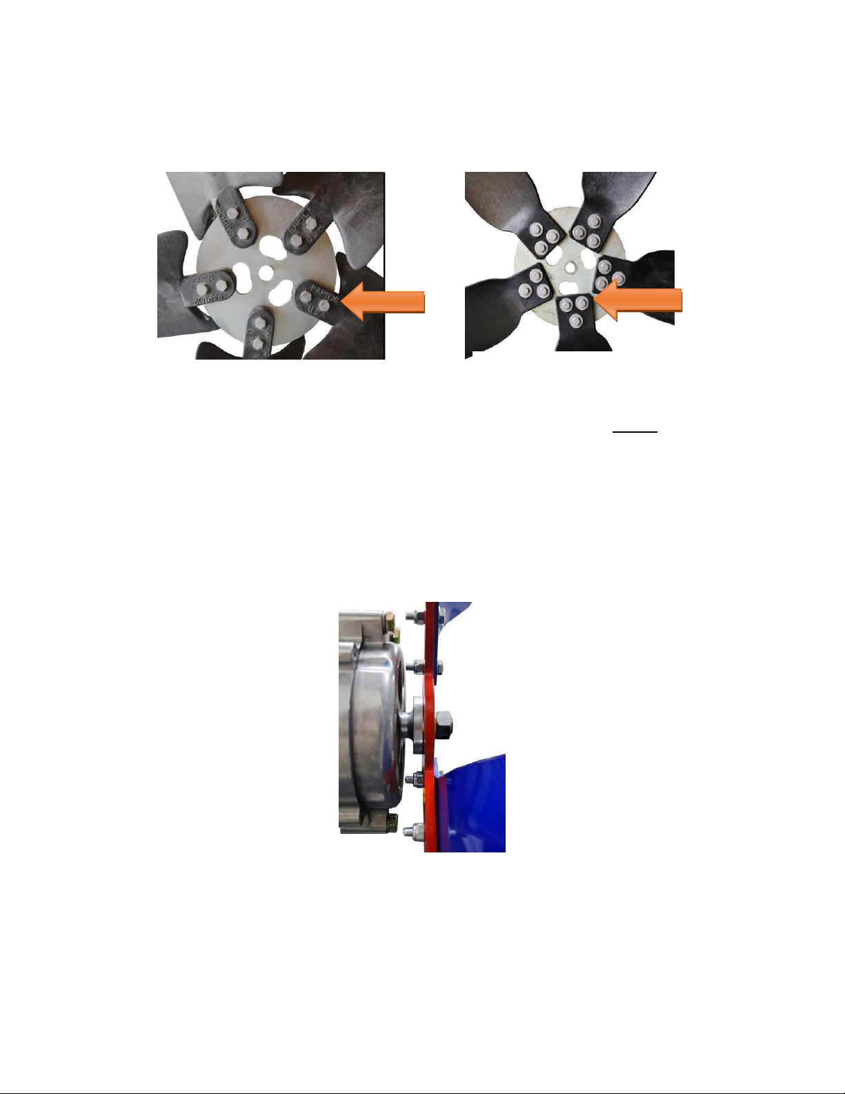
6. If the turbine severely shakes or vibrates, this is usually caused by one or more unbalanced blades or a
blade(s) installed backwards. If you have a bent blade that will not straighten itself over time, heat the
Last Revised 06/21/2018 Copyright © Missouri Wind and Solar, LLC 2017 pg. 9
blade using a heat gun or hair dryer until it is extremely warm, but not melting. While the blade is hot,
put a weight on the middle of the bend and let the blade completely cool. All Raptor blades have a
twist from the butt to the tip, and this is normal. Bent blades, however, rarely create problems with
turbine operation.
7. When the voltage of your battery bank rises, it takes more wind (torque) to continue charging the
bank. Our wind divert controllers are programmed to prevent overcharging the battery bank. Battery
bank and divert voltages:
▪12V Bank: 50% - 12.3V; 100% - 12.8V; Divert –14.4V
▪24V Bank: 50% - 24.6V; 100% - 25.6V; Divert –28.8V
▪48V Bank: 50% - 49.2V; 100% - 51.2V; Divert –57.6V
8. When a turbine outputs power, it creates heat. Sustained operation in high winds can cause heat build-
up and power loss, until the wind slows and the turbine cools down.
9. Check the wire, especially near connection points, and note how hot it is. If it is hot to the touch, then
you are using more amperage than the wire can handle. You will need to add more copper by doubling
up the wire or replacing it with larger cable.
10. A poor, sloppy, dirty, or loose connection typically causes heat buildup especially near the connection
point and will also result in significant power loss.
Last Revised 06/21/2018 Copyright © Missouri Wind and Solar, LLC 2017 pg. 10
Troubleshooting common problems:
a. Turbine does not charge battery bank:
1) Verify the PMG’s voltage matches the battery bank voltage (i.e. 12V PMG and 12V battery).
2) Ensure wire size is correct between all DC components, all electrical connections are correct and tightly
connected, crimped, or soldered.
3) Ensure DC positive and negative from turbine (via divert controller and/or rectifier, depending on
divert controller) are connected to the “Master Positive” and “Master Negative” battery bank
terminals. See Figure 16.
Figure 16
4) Ensure wind speed is sufficient to produce power, usually 6 MPH or greater.
5) If starting out with a fully charged battery bank, sometimes it helps to place a load on the bank, draw
down the voltage, then check for turbine power production.
6) Use DC ammeter (or shunt with gauge) to check for current off any DC positive wire between rectifier
and battery bank. Amount of current depends on wind speed. With turbine spinning and no current,
check electrical connections.
7) When your battery voltage rises it takes more wind to charge. A full battery bank at rest is 12.6V,
25.2V, etc. A charge controller will stop charging at 14.4v, 28.8v to keep batteries from being ruined.
8) When a wind turbine outputs power it creates heat, which can build up. Open faced PMA/PMG wind
turbines work best to keep themselves cool. Too much sustained output can cause heat buildup and
power production to decrease until the wind slows for some time.
9) There may be an open circuit (poor or no connection) on one of the phases from the wind turbine.
Check connections between the stator, jack, connection to wire, connection from wire to brake switch
(if applicable), brake switch internal contacts, brake switch to rectifier, rectifier internals, and so on
down to the batteries. It is easiest to begin checking connections at the lowest point and work upward.
10) Please make sure your rectifier positive and negative connections are correct. Note the actual + and –
symbols and make sure they connect to the charge controller accordingly.
Last Revised 06/21/2018 Copyright © Missouri Wind and Solar, LLC 2017 pg. 11
Wind Turbine Wattage & Voltage
Dump Load Size
1600W in 12V
600W –1200W
1600W in 24V
600W –1500W
1600W in 48V
600W –1500W
2000W in 12V
1200W - 1500W
2000W in 24V
1200W –1500W
2000W in 48V
1200W –1500W
NOTE: When the divert controller dumps, the battery bank is discharging energy to the diversion load
(resistors). Divert controllers will measure battery voltage levels every 5 seconds, on average. When
the battery voltage drops below the dump set point, the divert controller stops the dump. During the
dump, the PMG current is also sent to the dump load, but the function is primarily to drain the battery
bank’s excess voltage. Therefore, an undersized diversion load takes much longer for the battery bank
to lower its voltage level, thus the divert controller operates longer and gets hot.
NOTE: Use maximum dump load figures above when using an approved MPPT charge controller, if you
experience regular high winds, or have AGM or gel batteries or your batteries may overcharge.
c. Blades not spinning or seem unbalanced
NOTE: Check the ohms at the rectifier ONLY in a no-wind condition.
Ensure your test meter has a fully charged battery or it will read incorrectly. ONLY check the ohms (Ω)
when the turbine is not spinning or even slightly rocking back and forth and the DC side of the rectifier
is disconnected.
If the bridge rectifier is warm or hot when the turbine has been idle for an extended period, then the
rectifier either is defective or has the wrong polarity connected on the DC side.
You may need to check the ohms (Ω) of the 3 separate phases. You can do this at the 3 phase side of
the rectifier with your total length of power cord connected to the wind turbine.
The ohms of the 3 PMG's Stators:
•12v is 0.3 ohm phase to phase, 24v is 1.8 ohm, 48v is 6.7 ohm.
•You would check the ohms between the 3 phases on the AC side phase 1+2, 1+3, 2+3.
1) Make sure no wire's copper is touching another. Check the ohms/resistance between phase 1 + 2; 1
+ 3; 2 +3. If all read the same, for example 2 ohms each, then there is no short between phases
either in the rectifier, power cord, or copper windings (stator inside turbine motor (PMA/PMG).
2) If you read 20 ohms, 0 ohms, 2 ohms this means you have a phase shorted against another. Shorts
will cause havoc on your system and typically a failure (charring, burning) of the stator in the
turbine motor. It's like holding the brake pedal and accelerator down on your car at the same time!
If you have other 3 phase devices connected before or after the rectifier, check them for shorts as
well.
3) Ensure your bridge rectifiers are not wired in series (typically for a Freedom II or dual motor wind
turbine). If in series, your turbine motor will produce double the voltage and you will get lower
amperage and a noticeably lower speed of rotation from the blades. Optimally, you will wire your
rectifiers in parallel and see an increase in power and rotation speed.
4) The sealed bearings may take approximately 100 hours to fully break in and loosen up. Before this
break in period, the wind turbine might spin more slowly, especially in very low wind, and hamper
startup speed slightly.

Popular Wind Turbine manuals by other brands

Marlec Rutland FM910-4 owner's manual

Marlec

Marlec Rutland FM910-4 owner's manual

Enessere Hercules Installation stages

Enessere

Enessere Hercules Installation stages

Coleman 011-2044-8 user manual

Coleman

Coleman 011-2044-8 user manual

ista Breeze i-1500 Ongrid Translation of the original instructions

ista Breeze

ista Breeze i-1500 Ongrid Translation of the original instructions

Primus Wind Power Air X owner's manual

Primus Wind Power

Primus Wind Power Air X owner's manual

Natural Power ZephIR Operation & maintenance manual

Natural Power

Natural Power ZephIR Operation & maintenance manual

manuals.online logo
manuals.online logoBrands
  • About & Mission
  • Contact us
  • Privacy Policy
  • Terms and Conditions

Copyright 2025 Manuals.Online. All Rights Reserved.