Bergey 24 VDC B User manual

BWC XL.1
24 VDC
24 VDC24 VDC
24 VDCBattery Charging System
Owners Manual
Owners ManualOwners Manual
Owners Manual
Bergey Windpower Co., Inc.
2001 Priestley Ave.,
Norman, OK 73069 USA
Telephone: (405) 364-4212
Fax: (405) 364-2078
E-mail: [email protected]
Web: www.bergey.com
XL.1 Wind Turbine
PowerCenter Controlle
r
Version 1.1
January 2001

1
Please Help Us Improve This Manual
We would be very interested to hear any comments you might have on this
new owners manual. We are particularly interested in learning of mistakes or
omissions and subjects that are unclear. Please call, fax, or e-mail and direct
your comments to Steve Wilke in Customer Service. Thank you very much
for your assistance.
Tel: 866-237-4397 (toll-free in U.S.)
Tel: 405-364-4212
Fax: 405-364-2078
e-mail: swilke@bergey.com

2
BWC XL.1 Wind Turbine
24V Battery Charging System
OWNERS MANUAL
Table of Contents
1. Overview ……………………... 2
2. Cautions and Warnings …….. 2
3. Identification …………………. 3
4. System Description ………... 3
5. System Operation ………….. 4
6. Turbine Installation ………. 7
7. PowerCenter Installation ….. 10
8. Inspections and Maintenance 13
9. Trouble-Shooting ………….. 15
Installation Planning ………… 19
1. Overview
The BWC XL.1-24 wind turbine system is a state-
of-the-art small generator designed to charge bat-
teries and supply electrical loads in a 24 VDC DC-
bus based remote power system. When used in
conjunction with a suitable sine wave DC-AC in-
verter and a 24 VDC battery bank the XL.1-24 can
also be connected to the power grid.
The XL.1-24 turbine consists of a 2.5 meter (8.2
ft.), 37-kilogram (82 lb) wind turbine rated at 1,000
watts and a multi-function turbine and system con-
troller, the PowerCenter.
The XL.1-24 wind turbine features superior low-
wind-speed performance, very high system effi-
ciency, and low noise. The PowerCenter features
a solar regulator, a dump load capability, an
automated equalization function, and special cir-
cuitry to boost the low wind speed performance of
the XL.1 wind turbine.
The BWC XL.1-24 is offered with the optional
guyed tubular Tilt.Tower, which comes in heights
from 9 m (30 ft.) to 32 m (104 ft.). The Tilt.Tower
is shown in Figure 1. For installation procedures
on this tower please refer to the “BWC XL.1
Tilt.Tower Installation Manual”. This manual is
available on-line at http://www.bergey.com, from
BWC dealers, and from BWC directly.
Figure 1, XL.1 with 9 m Tilt.Tower
2. Cautions and Warnings
This manual contains important information on the
installation of your BWC XL.1 wind turbine and
PowerCenter controller. We strongly recommend
that you read and follow the instructions contained
in this manual.
At several points in the manual items of special
interest or significant impact are highlighted by
one of the following notices.
Warning
Hazards or unsafe practices that
could cause personal injury or death.

3
Caution
Hazards or unsafe practices that could
cause product damage.
Note
Significant points of interest
3. Identification
Each BWC XL.1-24 wind turbine has a serial
number decal located on the support structure
inside the nacelle. Since this label is only accessi-
ble by removing the nacelle it has been noted on
the Warranty Registration form. We recommend
writing it here as well.
BWC XL.1-24 Serial No.:
Each PowerCenter has a serial number decal af-
fixed to its side casing. This number has been
noted on the Warranty Registration form. We
recommend writing it here as well.
BWC PC.1-24 Serial No.:
4. System Description
XL.1 Wind Turbine Components
The major components of the XL.1 wind turbine
are shown in Figure 2.
A. Blades / Rotor System
The rotor system consists of three fiberglass
blades. Acting like aircraft wings, the blades con-
vert the energy of the wind into rotational forces
that can drive a generator. The airfoil on the XL.1
is the new SH3045 developed specifically for the
XL.1 by Bergey Windpower. The fiberglass
blades are exceptionally strong because they are
densely packed with glass reinforcing fibers that
run the full length of the blade. The rotor has three
blades because three blades will run much
smoother than rotors with two blades.
Blades
Tail Boom
Tail FinPowerhead Alternator
Tower
Mount
Spinner
Fi
g
ure 2, Ma
j
or Com
p
onents of the XL.1 Wind Turbine
Nacelle
B. Alternator
The alternator converts the rotational energy of
the rotor into electricity. The alternator utilizes
permanent magnets and has an inverted configu-
ration in that the outside housing (magnet can)
rotates, while the internal windings and central
shaft are stationary. The alternator was specially
designed for the XL.1 and produces power at low
speeds, eliminating the need for a speed-
increasing gearbox.
The output from the alternator is three-phase al-
ternating current (AC), but it is rectified to direct
current inside the nacelle. Since it uses perma-
nent magnets, the alternator is generating voltage
whenever the rotor is turning.
Warning
The output wiring of the BWC XL.1-
24 presents a low voltage shock haz-
ard whenever the rotor is turning.
Caution must be exercised at all
times to avoid electrical shock.

4
C. Nacelle
The nacelle is the fiberglass housing around the
main body of the machine. It contains the main
structural “backbone” of the turbine (called the
mainframe), the rectifier, the slip-ring assembly,
the yaw bearings, and the tower mount. The yaw
bearings allow the wind turbine to freely pivot
around the top of the tower so that the rotor will
face into the wind.
The slip-ring assembly is the electrical connection
between the moving (as it orients with the wind
direction) wind turbine and the fixed tower wiring.
The slip-rings and yaw bearings are located just
above the tower mount. The tower mount at-
taches the XL.1 turbine to the top of the tower.
D. Tail Assembly and AutoFurl
Operation
The tail assembly, composed of a tail boom and
the tail fin, keeps the powerhead (and, therefore,
the rotor) aligned into the wind at wind speeds
below approximately 12.5 m/s (28 mph). At about
12.5 m/s the AutoFurlaction turns the rotor away
from the wind to limit its speed. The tail appears
to fold, but in reality the tail stays stationary as the
powerhead turns sideways to the wind. The rotor
does not, however, furl completely sideways. This
allows the turbine to continue to produce power in
high winds. When the high winds subside the
AutoFurlsystem automatically restores the tur-
bine to the normal straight position.
E. PowerCenter
The PowerCenter, shown in Figure 3, serves as
the central connection point for the electrical com-
ponents in the system and it provides a number of
necessary and valuable control functions. Not all
of the available functions will be used in all instal-
lations. The PowerCenter also provides status
lights for the system and a handy light-bar “fuel
gage” for the battery bank.
Note
The XL.1 wind turbine will not perform
properly, particularly at low wind
speeds, without the PowerCenter con-
troller. The Power Boost circuitry in the
PowerCenter is needed to provide ac-
ceptable performance in wind speeds
below approximately 7.5 m/s (17 mph).
Figure 3, PowerCenter for the BWC XL.1
5. SYSTEM OPERATION
A. Normal Operation
The rotor of the BWC XL.1 should begin to rotate
when the wind speed reaches approximately 3
m/s (7 mph). Battery charging should commence
shortly after the rotor spins up to speed. Once
turning, the rotor will continue to turn in lower wind
speeds, down to approximately 2.5 m/s (6 mph).
Note
All operational wind speeds given as-
sume steady winds, sea-level altitude
and moderate temperatures. Hot
weather, high altitude, turbulence, and
gusting winds will reduce system per-
formance.
The rotor speed will increase with increasing wind
speed and the system will provide a higher output.
This output increases rapidly because the energy
available in the wind varies as the third power
(cube) of the wind speed. For example, if the
wind speed doubles from 5 m/s (11.2 mph) to 10
m/s (22.4 m/s), the energy in the wind increases

5
by a factor of eight (23= 2 x 2 x 2 = 8). One result
of this relationship is that there is very little energy
available in light winds. For the average site,
winds in the range of 5.5 – 9 m/s (12 – 20 mph)
will provide most of the system’s annual energy
production.
B. High Winds - AutoFurl
During periods of high wind speeds the AutoFurl
system will automatically protect the wind turbine.
When furled, the power output of the turbine will
be significantly reduced. In winds between 13 m/s
(29 mph) and 18 m/s (40 mph) it is normal for the
turbine to repeatedly furl, unfurl and then furl
again. In winds above 18 m/s (40 mph) the tur-
bine should remain continuously furled.
AutoFurl is a simple and elegant method of pro-
viding high wind speed protection. The AutoFurl
system is based on aerodynamic forces on the
rotor, gravity, and the carefully engineered ge-
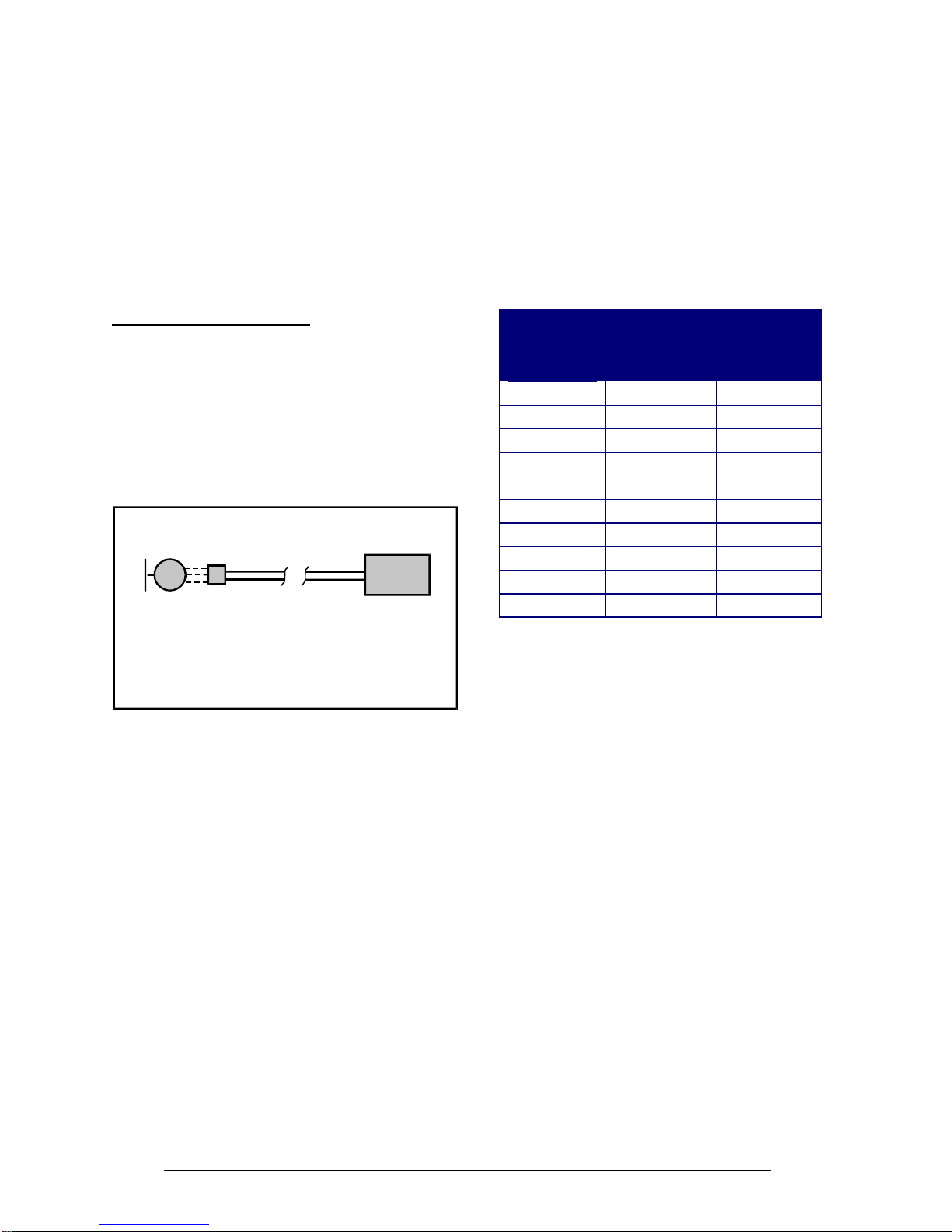
ometry of the wind turbine. As shown in Figure 4,
the aerodynamic forces acting on the blades
cause a thrust force pushing back on the rotor.
This force increases with increasing wind speeds.
Figure 4, AutoFurl
The thrust force acts through the centerline of the
rotor, which is offset from the centerline of the
tower pivot axis (yaw axis). Therefore, the thrust
force on the rotor is always trying to push the rotor
over to the side, away from the wind.
But the rotor is kept facing into the wind at speeds
up to ~ 12.5 m/s (28 mph) by the wind turbine’s
tail assembly. The tail, in turn, is kept straight by
its own weight because its pivot at the back of the
nacelle is inclined. So the weight of the tail holds
it against a rubber bumper and the tail holds the
rotor into the wind.
The geometries in the systems are carefully bal-
anced so that at ~ 12.5 m/s (28 mph) the rotor
force acting on the yaw-offset is large enough to
overcome the preset force holding the tail straight.
At this point the rotor will start turning away from
the wind or furling. The tail stays aligned with the
wind direction. The speed of furling depends on
the severity of the wind gusts and whether the
wind turbine stays furled depends on the wind
speed.
As the wind turbine furls the geometry of the tail
pivot causes the tail to lift slightly. When the high
winds subside the weight of the tail assembly re-
turns the whole turbine to the straight position.
The AutoFurl system is completely passive so it is
very reliable and since there are no wear points,
like in a mechanical brake system, it is very ro-
bust. AutoFurl was used in the very first wind sys-
tem produced by Bergey Windpower in 1980 and
in every unit produced since. AutoFurl is an im-
portant element of our success.
There is one situation in the field, however, that
we have found can disrupt the operation of Auto-
Furl. If the wind turbine is installed on a sharp hill
or next to a cliff so that the wind can come up
through the rotor on an incline (e.g., from below;
as opposed to horizontally) we know that this will
affect furling and can produce higher peak out-
puts. We strongly recommend avoiding this situa-
tion.
Caution
Do not install the XL.1 wind turbine near
cliffs or precipices or on sharp hills such
that the wind does not travel horizon-
tally through the rotor.
C. Unloaded Operation
As the battery bank voltage rises the PowerCenter
controller will try to regulate this voltage by switch-
ing off the solar charging and applying the op-
tional Extra Load (or “dump load”). If these
measures are not adequate then the PowerCenter
will momentarily disconnect the XL.1 wind turbine,

6
which allows the turbine to run unloaded. Under
unloaded operation the rotor will spin faster and it
will make more noise. In high winds the blades
may also “flutter”, causing a loud, low pitch growl-
ing sound.
The AutoFurl system works whether the turbine is
loaded or unloaded. Applying extra loads during
high wind periods can reduce the likelihood of
blade flutter.
D. PowerCenter Controller
The basic electrical schematic for the BWC XL.1
is shown in Figure 5. The XL.1’s alternator pro-
duces three-phase alternating current (AC) that
varies in voltage and frequency with the rotor
speed. The AC power is rectified to direct current
(DC) power by a rectifier module inside the na-
celle. Thus, the wire run from the wind turbine to
the PowerCenter is DC.
Alternator
Rectifier
(on turbine)
DC Wire Run
PowerCenter
Figure 5, XL.1 Basic Electrical Schematic
The PowerCenter for the XL.1 has two sets of
color-coded light-emitting-diodes (LED’s) for Sys-
tem Status and Battery Bank Status.
System Status Lights:
Solar Power (green): Lights up when the op-
tional solar panel(s) are charging the batteries.
Extra Load (red): Lights up when the optional
auxiliary or dump load is activated due to high
battery voltage.
Wind Power (green): Lights up when the XL.1
wind turbine is charging the batteries.
Power Boost (green): Lights up in low to
moderate winds to indicate that the low wind
speed performance optimizing boost circuitry is
operating.
Battery Bank Status Lights:
Battery bank charge status is shown with ten col-
ored LED’s, which act like a fuel gage for the re-
mote power system. This gage, however, is inex-
act and it is intended to provide only a general
indication of the energy reserves available in the
system. The following table shows the voltage
indicated by the highest lit LED and its approxi-
mate relationship to the battery capacity available.
LED No.
(from left
side)
Indicated
Battery
Voltage
Range
Approxi-
mate Bat-
tery Re-
serve
L1 (red) Below 22 V Below 5%
L2 (yellow) 22 – 23.5 V 5%
L3 (green) 23.5 – 24 V 15%
L4 (green) 24 – 24.5 V 30%
L5 (green) 24.5 – 25 V 60%
L6 (green) 25 – 27 V 90%
L7 (green) 27 – 28 V 100%
L8 (green) 28 – 29.5 V 100%
L9 (yellow) 29.5 – 30.5 V 100%
L10 (red) Above 30.5 V 100%
Table 1, Battery Bank Status Indications
The LED’s provide an indication of the instanta-
neous battery voltage. This voltage is affected by
the state of battery charge and the instantaneous
net current flow into or out of the battery. There-
fore, during high charging/low load periods the
gage will over-predict battery state of charge and
during low charging/high load periods the gage
will under-predict battery state of charge. Also,
the smaller the battery bank the more rapidly the
LED’s will change in response to changing wind
and electrical load conditions.
The PowerCenter is designed to work with
flooded-cell or sealed, deep-cycle, lead-acid bat-
teries. Do not use other types of batteries without
first contacting Bergey Windpower Co.
Battery Equalization
The PowerCenter has an automatic one-hour bat-
tery equalization function that is initiated using the
push button on the back side of the PowerCenter
enclosure. Equalization is a maintenance function
that brings the batteries up to a higher state of
charge and causes them to out-gas (bubble) ac-

7
tively. It should be performed approximately once
a month on a windy day.
To start the equalization process, press the button
on the back side of the enclosure (see Figure 11).
Note
Equalization will allow the battery bank
to reach 30 VDC, which may cause
some inverters to shutdown due to “in-
put over voltage”.
Caution
Do not equalize sealed batteries. The
out-gassing at high battery voltages will
damage them.
Always check the electrolyte levels in each battery
cell after equalization and add distilled water as
necessary. Do not add battery acid. The loss of
fluid is due to water being dissociated into hydro-
gen and oxygen. The sulfuric acid remains. The
production of hydrogen gas during charging is the
reason that battery enclosures should always be
ventilated.
Operation of Controls and Factory Settings
The PowerCenter will switch the XL.1, the optional
PV array, and the optional dump load on and off
to prevent battery overcharge and maximize en-
ergy capture. These switching functions are de-
termined by the battery bank voltage.
At battery voltages below 28 VDC, the wind and
solar are connected and allowed to charge the
batteries. If the battery voltage rises above 28
VDC the solar is switched off. At 29.5 VDC the
Extra Load (dump load) circuit is turned on. At
30.5 VDC the wind turbine is turned off.
As the battery voltage decreases back down to 28
VDC the wind turbine is turned on and the Extra
Load is turned off. At 27 VDC the solar is turned
back on.
When the equalization function is activated all
voltage set-points are raised by approximately 2
VDC.
6. Turbine Installation
Appendix 1 is an Installation Planning Guide. It
provides recommendations on tower heights and
locations, electrical components, and wiring.
Tower Mounting: The XL.1 wind turbine is at-
tached to its tower by a three-sided, six fastener
casting, shown in Figure 6, that is designed to fit
inside a tube with an inner diameter of 85 mm
(3.35 in). If you are using the BWC Tilt.Tower
then the XL.1 will bolt directly in place. If you are
mounting the XL.1 to a different type of tower then
you will need to ensure that the tower meets the
requirements for XL.1 towers (see Appendix) and
that it has a proper adapter fitting for attaching the
XL.1 tower mount casting (also defined in the Ap-
pendix)
Figure 6, Tower Mounting for the XL.1
Once you have the proper mounting arrangement
you can proceed with assembly of the wind tur-
bine. The fasteners on the XL.1 are all metric.

8
Tilt-up Type Towers: If you have a tilting
tower, such as the BWC Tilt.Tower, the following
procedure is recommended:
Tools Required:
17 mm box end wrench
17 mm socket and ~ 300 mm (12”) ratchet
drive
8 mm socket or wrench
pliers
crimpers for wiring terminals (U-shaped
crimp preferred over straight crimp)
thread locking compound (like Loctite 242)
tape measure, 12 ft.
Procedure:
Step 1:
With the tower tilted down, place the powerhead
of the wind turbine near the top end of the tower.
The tower wiring is connected to the XL.1 wind
turbine at the slip-ring using two small screws and
ring terminals crimped to the two conductors. Cut
the outer insulation on the wire back about 60 mm
(2.5 in). Strip the insulation off the outer 12 mm
(1/2 in) of each conductor and crimp on the ap-
propriate ring terminals (several sizes are pro-
vided to match possible wire sizes). Attach the
two power conductors to the slip-ring assembly
with the screws provided. The polarities of the
connections are marked. If your conductors are
color-coded we recommend making note of the
colors connected to positive and negative leads.
The slip ring assembly is not designed to support
the weight of the down-tower wire. A strain reliev-
ing installation is required, as shown in Figure 7.
Use the two nylon cable ties provided to secure
the tower wiring to the tower adapter casting. Af-
ter completing the connections, pull on the tower
wire to make sure that it is secure before mount-
ing the wind turbine on the tower.
Step 2:
Raise the tower about 1 meter (3 ft) off the ground
to provide room to assemble the XL.1 turbine. We
recommend fashioning a temporary support stand
to hold the tower up during turbine assembly.
Step 3:
Mount the wind turbine tower adapter to the top of
the tower using the six M10 x 1.5 bolts and six
washers. We strongly recommend applying Loc-
tite 242 (Thread Locking Compound) to the
threads prior to installation to reduce the likelihood
of loosening due to vibration. We recommend
using a torque wrench to achieve the proper fas-
tener torque on the tower mounting bolts. The
recommended toque is 54 N.m (40 ft-lbs).
Power
Cables
Nylon
Cable
Ties
Turbine
Mounting
Bolts
Figure 7, Turbine Mounting
Step 4:
Complete the wiring to the PowerCenter before
adding the blades. This is recommended so that
you can test the DC polarity of the wiring by spin-
ning the alternator by hand. It is very important
that the polarity [positive (+) and negative (-)] is
correct when the turbine is connected to the Pow-
erCenter. The best way to ensure this is to com-
plete the wiring and then test the polarity with a
Volt-Ohm-Meter.
Wiring recommendations are provided in Section
7 and in Appendix 1, section D. Turning the alter-
nator by hand will provide enough voltage to make
this check. Carefully mark the positive and nega-
tive electrical leads for later reference.
Step 5:
Turn the XL.1 powerhead upward so that the al-
ternator is facing up. Attach the blades as shown
in Figure 8 using the M10 hardware provided. We
recommend bolting one blade up solidly and leav-
ing the other two somewhat loose while you check
the tip-to-tip blade distance. We recommend
checking, and adjusting as necessary, the blade
tip spacing to ensure that the blade tips are
equally spaced. This step will help make the wind

9
turbine as smooth running as possible, which will
maximize the operating life of the bearings and
reduce vibration related noise. The blade tip-to-tip
distances should not differ by more than 12 mm
(1/2”) for smooth operation.
We recommend using a torque wrench to achieve
the proper fastener torque on the blade nuts. The
recommended toque is 54 N.m (40 ft-lbs). Loctite
is not necessary on the blade fasteners because
the nylon locking nuts provide adequate locking.
Step 6:
Attach the spinner (nose cone) using the three M5
bolts and washers provided, as shown in Figure 8.
We recommend applying Loctite to the bolt
threads prior to assembly.
Longer bolt
goes here
Blade Nuts &
Washers
Blade Bolts
Spinner
Fasteners
Figure 8, Blade and Spinner Fasteners
Step 7:
Bolt the tail fin to the tail boom using the eight M5
bolts and lock-washers provided, as shown in
Figure 9. We recommend applying Loctite to the
bolt threads prior to assembly.
Step 8:
Place the tail boom on the rear of the turbine
powerhead and insert the 12 mm (1/2”) tail pivot
pin from the top. If the parts are aligned properly
the pin should insert easily. Do not use a hammer
to pound the pin in place, as this may cause scor-
ing of the bronze bushings. Secure the tail pivot
pin with two cotter pins, as shown in Figure 10.
Note: Two M12 washers are provided to go on
the Tail Pivot Pin between the cotter pins and the
tail boom. They are not shown in the drawing for
Figure 10, but must be installed. Failure to prop-
erly install and secure both cotter pins will lead to
loss of the tail boom.
Figure 9, Tail Fin Attachment
Tail Fin Fasteners
Cotter
Pin
Cotter
Pin
Tail Pivot
Pin
Figure 10, Tail Boom Attachment
Note: Install M12 Flat Washers
between cotter pins and tail boom.

10
Step 9:
Check the XL.1 wind turbine carefully to make
sure that the installation is complete. We recom-
mend the following checklist:
!"
Blade fasteners are secure and prop-
erly torqued
!"
Blade tips are evenly spaced
!"
Spinner is secure
!"
Tail fin is secure
!"
Tail pivot pin is locked in place with
both cotter pins and washers.
!"
Tower adapter bolts are secure
!"
Wiring polarity is tested and marked
Step 10:
Dynamically brake the XL.1’s alternator by con-
necting the positive (+) and negative (-) output
leads together. The resulting short-circuit will
keep the rotor from spinning during tower raising.
Step 11:
Raise the tower following the procedures outlined
by the tower supplier. Please make safety your
top priority.
Non-tilting Towers: On a non-tilting tower,
such as a fixed guyed tower or a self-supporting
pole type tower, there are two general approaches
that can be used: 1) assemble the tower and tur-
bine together on the ground and then use a light-
duty crane to set the tower in place, or 2) erect the
tower and then lift the wind turbine to the top with
either a light-duty crane or a gin-pole.
A gin-pole, in this case, is a tower assembly tool
that attaches to the tower and provides an arm
with a pulley so that parts can be hoisted above
the top of the tower. Gin-poles are used by pro-
fessional tower erectors and we do not recom-
mend their use by non-professionals. We know of
at least one homeowner who died approximately
fifteen years ago while improperly using a gin-pole
to install a small wind turbine (though not a Ber-
gey turbine).
Where possible we recommend the first general
procedure because it allows work to be done
more safely, on the ground. In this case please
follow the general procedure for turbine assembly
provided in the preceding section. When raising
the tower you must lift the tower, not the XL.1
wind turbine. The XL.1 cannot support the weight
of the tower.
For customers installing a BWC XL.1 on an exist-
ing fixed tower we recommend that you use a
crane to lower the tower so that you can attach
the turbine on the ground. Alternatively, we rec-
ommend you use a bucket-truck, like the type
used by utility linemen. Check with local sign
companies because they often offer bucket-truck
services at reasonable hourly rates. If neither of
these approaches is possible then we recommend
that you engage the services of professional wind
turbine or tower erectors to install your wind tur-
bine.
The procedures for hoisting the BWC XL.1 using a
gin-pole are available from Bergey Windpower.
Please contact Customer Service for assistance.
7. PowerCenter Installation
A. Electrical System
The general electrical configuration for BWC XL.1
and hybrid system installations is shown in Figure
11. In most cases the loads will be AC (alternat-
ing current) and they will be supplied through a
DC-to-AC inverter.
Figure 11, Typical XL.1 System Configuration
Alternator
Rectifier
(on turbine)
DC Wire Run
(Tower &
Ground) PowerCenter PV Array
DC Source Center
(optional, used on
larger systems)
Battery Bank
AC Loads
Back-up Generator
or Utility
Inverter
(connected to
DC Source, if
available)
=
~

11
The PowerCenter has a limited current carrying
capacity so we recommend that you use a DC
Source Center whenever you have multiple XL.1
wind turbines. DC Source Centers are available
from Bergey Windpower.
Additional Design Guidance:
1. If you have multiple XL.1 turbines and
PowerCenters, do not connect more than
one wind turbine to one PowerCenter.
2. Connect multiple PowerCenters to a DC
Source Center via the PowerCenter’s bat-
tery terminals.
3. Do not connect the PowerCenter to an-
other controller that could disconnect the
PowerCenter from the batteries. The
PowerCenter should not be disconnected
from the battery when there is input from
the wind turbine.
B. Location
The PowerCenter must be installed indoors and
should be located relatively close to the battery
bank. Do not install the PowerCenter outdoors; it
is not waterproof.
C. Mounting:
The PowerCenter needs to be mounted vertically
to a wall, or other support structure, so that air can
pass unobstructed through the passive cooling
channel behind the enclosure. We recommend
setting the height of the LED’s at eye level if pos-
sible so that the system status lights will be easi-
est to read.
The enclosure dimensions and mounting layout
for the PowerCenter are shown in Figure 12. The
PowerCenter should be mounted with four M4
(0.157” dia.) screws. We recommend the follow-
ing procedure:
Tools Required:
Pencil
Carpenters level
Drill with ~ 2 mm or 0.09” dia. drill bit
(4) M4, 1/8”, or 5/32” screws
Screwdriver
Procedure:
Step 1:
Mark the mounting hole locations using the Pow-
erCenter enclosure as the template. Use a car-
penters level to check the levelness of the enclo-
sure before marking the holes.
Step 2:
Drill small (~ 2.5 mm or 0.1 in diameter) pilot holes
for the mounting screws.
Step 3:
Screw the top two mounting fasteners into the wall
until ~ 6 mm (1/4”) of the shank extends out from
the wall.
Step 4:
Remove the PowerCenter cover and place the
PowerCenter enclosure on the two upper mount-
ing fasteners. Slide the enclosure down such that
the fasteners are placed at the top of the inverted
“T-slots”.
Figure 12, PowerCenter Mounting Dimensions
390 mm
15 3/8“
15.375“
128 mm
5.0“
337 mm
13 1/4“
13.25“
Bottom View
Front View
Enclosure Dimensions
267 mm
10 1/2“
10.5“
333 mm
13 1/8“
13.125“
3.8 mm
0.150“
Diameter
4 Places
Mounting Hole Layout
Equalize Button
Back View
Step 5:
Install the bottom two mounting fasteners, and
then tighten the top two fasteners.

12
C. Wiring
All wiring should conform to the National Electric
Code or other governing local electrical code.
The use of electrical conduit for wiring between
components is highly recommended. If you have
any connections with dissimilar metals (aluminum
/ copper) they should be coated with an anti-
oxidation compound to prevent galvanic corrosion.
All loads should be protected by fuses or circuit
breakers to avoid hazards from accidental short
circuits.
The wind turbine tower must be well grounded
and a good quality lightning surge arrestor, con-
nected to a good quality earth ground, should be
installed on the wiring from the wind turbine. We
recommend a Delta LA302DC arrestor installed
into the third (from the left) rear entrance hole of
the enclosure. This tucks the arrestor neatly be-
hind the enclosure. The arrestor leads are con-
nected to the wind turbine terminals.
We do not recommend grounding either the nega-
tive or positive DC bus on the PowerCenter.
However, some inverter manufacturers recom-
mend grounding and some electrical codes re-
quire it. If you do ground the PowerCenter,
please conform to local practices for grounding
either the positive or negative bus.
D. PowerCenter Connections
Cable Entrances: As shown in Figure 13, wiring
can be connected to the PowerCenter from below
or behind or in a combination of both. A total of
eighteen 7/8” (~ M20) entrance holes are pro-
vided.
Box Lugs: The PowerCenter is supplied with box
lugs (not shown in Figures 12 and 13) that are
used to connect electrical leads to the terminals
on the PowerCenter circuit board. These lugs can
accommodate wire sizes from 3.35 mm2to 7.1
mm2(8 AWG to 2 AWG).
Plastic Grommets and Plugs: The PowerCenter
is supplied with a number of plastic grommets and
plugs for the wire entrance holes at the bottom of
the enclosure. Grommets should be used to pro-
tect incoming wires from the hard edge of the
aluminum. They are not necessary if you are us-
ing conduit or special cable entrance fittings.
Holes not used for wiring should be sealed using
the plastic plugs. Even though 24 VDC is gener-
ally not considered a lethal voltage, most electrical
codes will require that the unused entrance holes
be sealed and we believe that this is prudent and
the safest course of action.
Figure 13, PowerCenter with Cover Removed
We recommend the following procedure for mak-
ing the electrical connections:
Step 1:
Remove the cover to expose the circuit board and
terminals. The terminals are on the circuit board,
as shown in Figure 14.
Figure 14, Terminals for Electrical Connections

13
Step 2:
Connect Dump Load leads. This is an optional
resistance-heating load that will operate when the
batteries are full. Polarity is not important in mak-
ing this connection.
The specification for the dump is 1 Ohm or higher,
with at least a 1,000 Watt capacity.
Step 3:
Connect Wind Turbine leads. The 60A circuit
breaker on the side of the circuit board should be
switched to “Off”. Please ensure that the wind
turbine wires are connected with the proper polar-
ity. The system will not operate correctly and
could be damaged if the polarity is reversed. The
polarity can be checked with a Volt-Ohm-Meter,
but it does require that the XL.1 alternator be ro-
tated.
Step 4:
Connect Battery leads. Please ensure that the
battery leads are connected with the proper polar-
ity. The system will not operate correctly and
could be damaged if the polarity is reversed. Al-
ways check the polarity with a Volt-Ohm-Meter
before making connections.
The maximum current to the batteries will be ~ 60
amps with no PV and up to ~ 90 amps with the
maximum allowed PV array size. Wiring to the
batteries must be sized accordingly.
Step 5:
Connect PV leads. Please ensure that the PV
leads are connected with the proper polarity. The
system will not operate correctly and could be
damaged if the polarity is reversed. Always check
the polarity with a Volt-Ohm-Meter before making
connections.
The maximum current capacity of the PV regulator
circuit on the PowerCenter is 30 amps, or ap-
proximately 900 Watts.
Step 6:
Connect Inverter. If the system includes a DC to
AC inverter, connect the inverter input leads to the
battery terminals or DC source center, not to the
PowerCenter. The PowerCenter circuit board is
not designed to handle the high currents that are
possible with inverters.
Step 7:
Connect Loads. If the system includes 24 VDC
loads connect them to the battery terminals or DC
source center.
Step 8:
Reinstall the cover. Switch the 60A circuit breaker
to “On”.
The XL.1 wind turbine system is now ready to op-
erate.
8. Inspections and Maintenance
The BWC XL.1 installation should be inspected
after 30 days and then again 180 days after instal-
lation. Following these two inspections the instal-
lation should be inspected every two years and
after any particularly severe weather. In corrosive
marine environments more frequent inspections
are recommended. Inspections should be done
on days when the wind is below 7 m/s (16 mph).
Check List for Inspections
1. Inspect each of the anchor points. Ensure
that all hardware is secure and the guy wires
are properly tensioned. Check to ensure that
no strands are broken.
2. Short the alternator using the procedure given
in the next subsection. Climb or lower the
tower. Always use proper safety belts and
lanyards when climbing.
3. Inspect the blades for:
A. Condition of the leading edge, particu-
larly out near the tip.
B. Tip damage.
4. Remove the spinner. Check the torque on the
blade nuts; the recommended value is 47 N.m
(35 ft-lbs). Check the front bearing cover for
seal integrity and grease loss. Reattach the
spinner and check that it is secure.
5. Check the screws holding the nacelle rubber
bumpers and tail fin in place.
6. Check the cotter pins and washers on the tail
pivot pin.

14
7. Check the torque on the tower mounting
bolts; the recommended value is 54 N.m (40
ft-lbs).
8. Check for cracks or loose hardware on the tail
boom and fin.
9. While descending the tower or before raising it,
inspect the following:
A. Check that the tower wiring is properly
secure.
B. Check all tower fasteners.
C. Look for any cracks in the tower structure.
D. Check the condition of the guy wire at-
tachments.
10. Check the connection on all ground rods and
hardware.
11. Inspect the surge arrestor(s). Replace if
there are signs of damage.
12. Remove the alternator shorting connection.
13. Listen to the sound of the machine as it
speeds up. No mechanical sounds, such as a
"clunking" or "banging," should be heard.
Also watch for any new or significant vibration.
Some “growling” from the alternator is normal.
The turbine operation should be very smooth.
14. Inspect the wire run, particularly all electrical
connections.
15. Check condition of all wiring connections into
and out of the PowerCenter.
Warning
Only qualified personnel with proper
safety equipment should climb the
tower. Never climb the tower when
the rotor is turning.
Preventive Maintenance
We recommend that the bearings be re-packed
(re-greased) every 8-12 years. There are four
tapered roller bearings, two for the alternator and
two for the tower adapter. They are all the same
size (Timken L44643/L44610). There are two
bearing seals and we recommend that these be
replaced when the bearings are re-packed.
The strength of the blades, particularly at the root
(inner) end, may degrade over time due to flexure
and UV degradation of the fiberglass material.
The symptom of degradation is a reduction in
blade stiffness fore-and-aft. The blades have to
become very flexible in the fore-aft direction be-
fore there is any risk of tower strikes during se-
vere weather. We recommend that you check
blade stiffness about every 10 years and replace
the blades if they become extremely flexible.

15
9. Trouble-Shooting Problems
The following guide can be used to pinpoint the cause of operational problems with the BWC XL.1 wind
turbine and the PowerCenter controller. For problems or symptoms not found in the following listing,
please contact the Service Department at Bergey Windpower Co. at:
Tel: 405-364-4212
Fax: 405 364-2078
PROBLEM CAUSE(S) DIAGNOSIS REMEDY
Battery voltage gets
too high. PowerCenter regulating
voltage set too high or
no dump load being
used.
Excessive battery gas-
sing. Use voltmeter to
check battery cell volt-
ages or hydrometer to
check the specific grav-
ity – compare to battery
manufacturers recom-
mendations.
Contact the BWC Ser-
vice Department for the
voltage regulation set-
point adjustment proce-
dure.
Batteries do not reach
full state of charge. PowerCenter regulating
voltage set too low. Use hydrometer to
check the specific grav-
ity of the battery cells.
Compare with battery
manufacturer’s recom-
mendation.
Contact the BWC Ser-
vice Department for the
voltage regulation set-
point adjustment proce-
dure.
Loads are too large. Remove largest load. If
battery bank reaches
higher state of charge,
then the system is over-
loaded.
Consult with BWC about
possible remedies.
Rotor turns, but the
system doesn’t charge
the batteries.
Open circuit breaker. Check circuit breaker on
the side of the Power-
Center.
Switch to “On”
Blow output fuse. No lights on PowerCen-
ter. Replace 90A battery
fuse on PowerCenter
circuit board.
Power transistor failure. Turbine voltage is
above 10 VDC and Tur-
bine light is on, but no
current is being deliv-
ered.
Return complete Pow-
erCenter to BWC for
repair.
Turbine rectifier failure. Check voltage from the
turbine. Replace rectifier as-
sembly.

16
PROBLEM CAUSE(S) DIAGNOSIS REMEDY
Rotor makes a loud
“buzzing” sound dur-
ing high winds.
Blade flutter, due to
unloaded operation in
high winds.
Battery is at high state
of charge (L6 or higher
LED’s are lit). Turbine
power LED goes out
during wind gusts, indi-
cating that the turbine is
unloaded. Rotor buzz-
ing may be amplified by
tower.
Turn on additional
loads. Add dump load,
so turbine is not
unloaded during charge
regulation.
Rotor makes a high
pitch “whistling”
sound.
Blade tip damage. Check condition of
blade tips. Repair damaged blade
tips with automotive
“body putty” (polyester)
Rotor is unbalanced,
causing the turbine to
move slightly back
and forth as it spins.
Blade tips not evenly
spaced. Check tip-to-tip dis-
tances with a tape
measure. They should
be within 6.5 mm (¼”).
Loosening one blade at
a time, adjust the tip
spacing to bring dis-
tances within specifica-
tions.
Ice build-up on blades. Visual inspection. Se-
vere icing is very obvi-
ous.
Take no action. Do not
stand under machine.
The ice will be shed
when there is sufficient
sun and wind.
Wind is higher than 16
mph, but rotor will not
turn.
Short in power leads. Check connections first.
Isolate power leads.
Use VOM to check for
short circuit.
Repair short circuit.
Power transistor or
MOV (varistor) failure. Switch turbine circuit
breaker “Off” on Pow-
erCenter. Turbine
should start.
Return complete Pow-
erCenter to BWC for
repair.
Disconnect turbine and
check with diode meter.
Should read “IV” in one
direction and “OL” in the
other direction.
Replace rectifier.

17
PROBLEM CAUSE(S) DIAGNOSIS REMEDY
PV is not on, even
though sun is shining. Voltage of battery is
near regulation. Turn on additional loads
to pull down battery
voltage. See if PV turns
on.
Normal operation.
PV hooked up back-
wards. Check polarity. Reverse leads.
PV fuse blown. Check fuse with VOM. Replace fuse.
Dump load does not
work. Fuse blown. Check fuse with VOM. Check resistance of
dump load, should be
no less than 1 ohm.
Replace fuse.
Voltage below regula-
tion. Check battery bank
voltage with VOM. If it
is below 28-29.5 VDC,
the dump load should
not be coming on.
Normal operation.

18
Appendices

19
Appendix 1
Installation Planning
The location and height of the tower for the BWC
XL.1 wind system will be important factors in de-
termining the overall performance of the system.
Average wind speed is influenced by many things
and may vary considerably within a relatively
small region, particularly in complex terrain. Site
and tower choice, however, are often limited by
such factors as zoning restrictions, property size,
proximity to neighbors, customer preferences, and
wiring costs. All of these factors should be taken
into consideration in choosing the best tower site
and height.
A. Legal Restrictions and Good
Neighbor Relations
One of the first steps in planning an installation is
to determine the legal status of the proposed wind
turbine installation in the community in which it will
be installed. In most cities and some counties an
installation will be subject to zoning laws and
building codes. Some neighborhoods have pro-
tective covenants that limit the types of home im-
provements. In areas requiring permits the instal-
lation must be planned weeks to months in ad-
vance to allow time for applications to be proc-
essed and, if necessary, hearings to be held.
The quickest way to determine the local codes
and requirements is to call or visit the office of the
building inspector. Few cities have specific regu-
lations dealing with wind turbines, but most will
have height restrictions, building code require-
ments, and a formal process for obtaining a build-
ing permit. The most common problem encoun-
tered in the United States is a height restriction of
10.7 meters (35 feet), particularly in residentially
zoned areas.
The 9 m (30 ft) Tilt.Tower meets the 35 ft restric-
tion, but it does so at some loss in performance.
If you need or want to go higher than the zoning
height restriction you must apply for a variance. A
variance is essentially permission to break a rule
and it is granted following a public hearing before
a Planning Board. Obtaining a variance is a major
undertaking, costing $200-5,000 and taking sev-
eral months, so it is important to establish whether
it will be necessary as soon as possible.
Bergey Windpower Co. has experience in working
with customers and BWC dealers in variance
hearings and we offer advice and assistance to
those who request it.
Generally, in order to obtain a building permit you
will be required to submit a plot plan and fill out an
application. A plot plan is a map, drawn to scale,
of your property showing the boundaries, dwell-
ing(s) and other structures, major topographic fea-
tures, easements, and, most importantly, the loca-
tion and height of the proposed wind turbine
tower. Often you will be required to submit plans
for the tower and information on the wind turbine.
In some cases you will also be required to submit
a structural analysis of the tower to show that it is
in compliance with the building code. Sometimes
a registered Professional Engineer (PE) must sign
this analysis and occasionally the PE must be li-
censed in the State where the unit will be in-
stalled.
Bergey Windpower Co. has engineering analyses,
PE-Certified, for most towers it offers and copies
of these analyses are available to our customers.
Noise data is occasionally required and will soon
be available for the XL.1 from Bergey Windpower
Co.
If your property size is several acres or more then
the turbine will likely be so far from the nearest
neighbor’s house that they will not be bothered. It
is, none the less, strongly recommended that you
contact your nearest neighbors well in advance of
any construction to let them know that you are
installing a wind turbine. This is doubly good ad-
vise if your property size is less than several acres
or you have to obtain a variance for a building
permit. Good neighbor relations boil down to
treating your neighbors the same way you would
like to be treated and showing respect for their
views. An example of what not to do is to put the
turbine on your property line so that it is closer to
a neighbors house than to your own and not give
those neighbors any advance notice of your inten-
tions.
In general, we do not recommend that a BWC
XL.1 be installed on property of less than one-half
acre in size. We say this because the impact of a
wind turbine on the neighbors in such a “tight”
area is significant and the potential for disputes is
too great.
If you have questions about procedures, require-
ments, or tactics, please contact us. Since so few
This manual suits for next models
1
Table of contents
Other Bergey Wind Turbine manuals