Everlast lighting Victory Series User manual

2017 1
Cautions
1. Make sure power is removed or turned off before installing product.
2. This product must be installed in accordance with the applicable
installation code by a person familiar with the construction and
operation of the product and hazards involved.
3. The product must be installed in accordance with the National
Electrical Code and all applicable local codes. Proper grounding is
required for safety.
Victory Series Installation Instructions
1. Veillez à ce que le pouvoir est supprimé ou désactivé avant
d’installer le produit.
2. Ce produit doit être installé conformément au code d’installation
en vigueur par une personne familière avec la construction et
l’exploitation des produits et des risques impliqués.
3. Le produit doit être conforme au Code électrique National et tous
les codes. Raccordée à la terre est nécessaire pour la sécurité.
Précautions
Mounting
• Surface Mount: Use Mounting Bracket Dimensions or use specified mounting bracket to mark position on mounting surface.
Drill holes for mounting fixture and one for passing power cord through.
• Place power cord through designated hole into mounting surface. Align mounting bracket with corresponding holes, secure
bracket to surface using hardware rated for weight of fixture.
• If applicable, move adjustable brackets to desired angle and secure.
• Pole Mount: Make sure pole is suitable for fixture mounting. Place fixture onto pole and secure using properly rated hardware.
• If applicable, move adjustable brackets to desired angle and secure.
Wiring
• After fixture is securely mounted, connect supply line to fixture power cord. Connections must made within mounting pole or
within mounting bracket when applicable.
Photocell
• Eye of photocell must face approximately North. See Photocell Orientation Instructions for simple orientation procedure.
Knuckle Slip
Fitter
120W Fixture
(Top View)
(Back View)
(Top View)
(Back View)
240W & 350W Fixture

2017 2
• Make sure power is of or removed before making any electrical connections.
• All connections must be completed within junction box located on top of fixture or within an appropriately rated junction
box near fixture. All electrical connections must be in-line with standards set by the National Electrical Code and all
applicable local codes.
• All cords must be appropriately secured to corresponding receptacle.
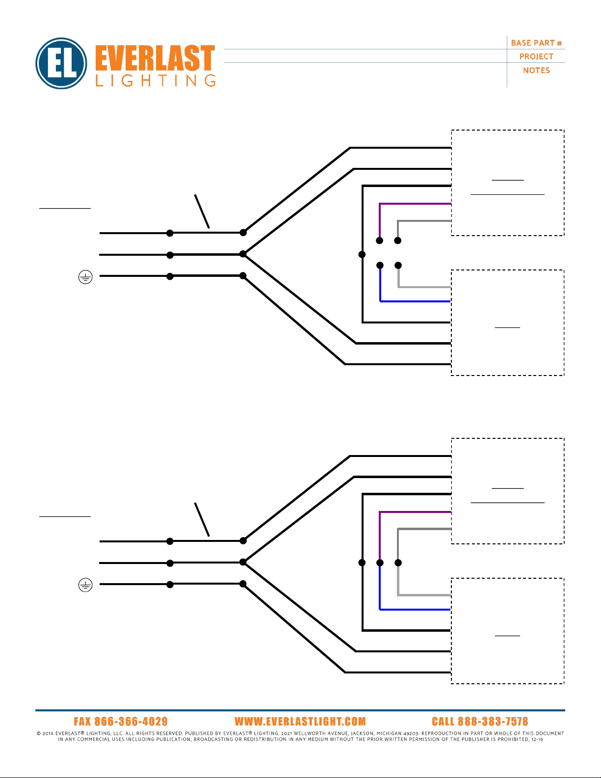
Wiring Diagrams
LINE
NEUTRAL
GROUND
120-277V AC
L1-LINE
L2-NEUTRAL
GROUND -
Driver
Factory Installed Power Cord
Standard 120-277 V
Photocell
or
Blank Photocell
120-277V AC
L1-LINE
L2-NEUTRAL
GROUND -
Driver
Factory Installed Power Cord
Photocell
or
Blank Photocell
Surge Module
Standard 120-277 V with Surge Protection
LINE
NEUTRAL
LOAD
LINE
NEUTRAL
GROUND
LINE
NEUTRAL
LOAD
LINE
NEUTRAL
GROUND
2017 3
120-277V AC
L1-LINE
L2-NEUTRAL
GROUND -
Driver
Factory Installed Power Cord
Bi-Level
Occupancy Sensor
White (-)
Blue (+)
Gray (-)
Violet (+)
On/Off
LINE
NEUTRAL
GROUND
120-277V AC
L1-LINE
L2-NEUTRAL
GROUND -
Driver
Factory Installed Power Cord
Bi-Level
Occupancy Sensor
White (-)
Blue (+)
Gray (-)
Violet (+)
Bi-Level
LINE
NEUTRAL
LOAD
LINE
NEUTRAL
LOAD
LINE
NEUTRAL
GROUND

2017 4
120-277V AC
L1-LINE
L2-NEUTRAL
GROUND -
Factory Installed Power Cord
347-480 V
BLACK/NEUTRAL (Primary)
LINE
NEUTRAL
GROUND
Driver
Photocell
or
Blank Photocell
RED/LINE - (Primary)
BLUE/LINE - (Secondary)
BLACK/NEUTRAL (Secondary)
480v Transformer
LINE
NEUTRAL
Photocell Orientation Instructions
• After fixture installation, make sure eye of photocell is orientated properly.
• If reorientation is needed, locate North position on photocell receptacle.
• Loosen both screws securing receptacle to fixture, rotate receptacle 180o,
tighten screws to secure receptacle to fixture.
• Place photocell into receptacle and turn to lock into position.
Photocell
Photocell Receptacle Receptacle Screws
LOAD
2017 5
Maintenance
*Review EverLast Lighting Inc. warranty for a list of components covered under warranty.*
NOTE: For employee safety, all power connections shall be turned off or removed before performing any maintenance on lighting fixtures.
Persons performing maintenance shall be familiar with construction and operation of product, plus the hazards involved.
Cleaning Schedule
To maintain proper efficiency of luminaire, a regular cleaning schedule needs to be established in regards to the placement, location and
conditions of product installation. Frequency of cleaning shall be to the discretion of the end user, but should be no less than every 90 days. If
conditions mandate, a more frequent cleaning schedule must be implemented. Improper cleaning may result in component malfunctions, product
failure and voidance of warranty.
Fixture Cleaning
If applicable –use air to blow dust and debris from lens, hood, heatsinks and drivers before wiping with a cleaning solution.
Use only mild, nonabrasive cleaners. Spray cleaner onto
soft
cloth and wipe surface of lens before wiping down other surfaces of lighting fixture.
If needed –use a very
soft
brush or duster to remove excess particles from between heatsinks, drivers or other difficult to reach areas.
Note any damage (cracking, splitting, peeling, breaks). Contact local sales representative, distributor or EverLast Lighting Inc. if damage
replacement is necessary.
Hardware
Fixture hardware shall be inspected before each cleaning.
Check to make sure all hardware connections are secure. Make sure to tighten any loose screws, bolts, nuts, liquid tight connectors, strain reliefs or
electrical connections.
Note any instances of damaged hardware. If any hardware is found to be consistently loose, damaged or questionable in any manner; contact local
sales representative, distributor or EverLast Lighting Inc.
Electrical Connections
Check electrical connections each time maintenance is performed.
Check to make sure all components (drivers, sensors, transformers, etc.) are properly connected and secured.
Proper wiring connections and ground are imperative for fixture performance and customer safety.
Safety Cables (if applicable)
Safety cables shall be regularly inspected during cleaning cycles.
Check to make sure cables and connectors show no signs of damage. If damage is found contact local sales representative, distributor or EverLast
Lighting Inc. for replacements cables right away.
Table of contents


