Cat. No: 0 626 25
Technical data sheet: S000104007EN-1 Updated: Created: 30/09/2019
CONTENTS 3/30
Self-testing Addressable self-contained
emergency evacuation lighting unit
2. INSTALLATION (continued)
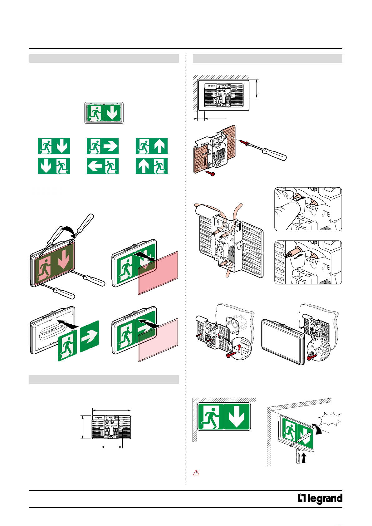
• Replacing an existing unit with a 0 625 25 unit while keeping the
old plates:
* For plates from 1998 to 2010 you should turn the unit upside down
and reposition the pictogram, in which case the unit protection rating
becomes IK 05.
Attach a maintenance label Cat. No. 0 60900 and write the commissioning
date on it.
3.4 Automatic checking of the unit status (self-testing
system)
This unit automatically checks its operating status.
Once a week:
Switches to emergency state and tests the light source for 15 s.
Once every three months:
Switches to emergency state and tests the light source and the standby
battery power time.
3. OPERATION
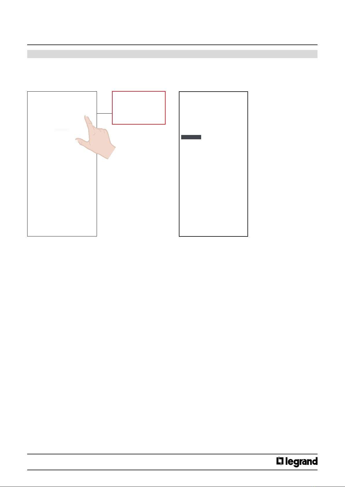
3.4.1 Result of the automatic checks
3.4.2 Stopping a test in progress
If a manual autonomy test hinders operation, it can be stopped immediately.
Press the O button on the remote control Cat. No. 0 625 20/21
or 0 039 00/01. The test is stopped and postponed until the following day.
The time of the tests is set at the time the unit is rst switched on. The
day of the test is chosen randomly in order to ensure that a minimum
number of units is tested at the same time.
The time at which all the units are tested can be changed to the required
time by simultaneously pressing the On and O buttons
on the remote control.
LEDs Luminaire
OK
Battery
fault Other fault(s)
Green
(steady or
flashing)
Yellow
(steady)
(rapid flashing)
*
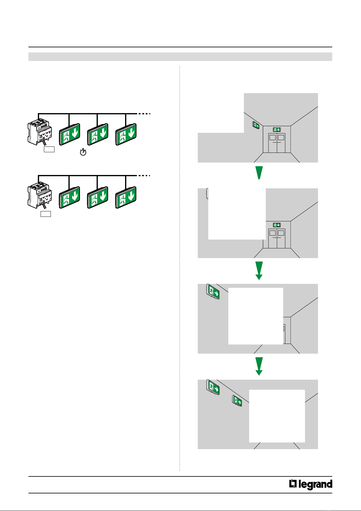
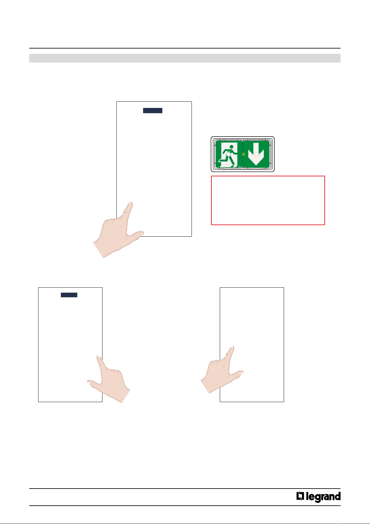
3.5 Increased visibility
This new function is used to make the self-contained emergency
lighting unit pictograms more visible in the event of evacuation due to a
re alarm with mains power present.
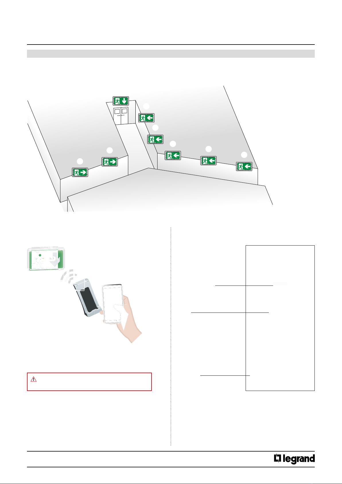
This self-testing addressable self-contained emergency lighting unit
incorporates two operating modes: self-testing mode and addressable
mode.
Self-testing mode
This lighting unit is factory-congured in self-testing mode, and can
therefore be used in this mode without any alteration..
Addressable mode
This lighting unit can also be used on an addressable system. For
this it must be addressed using conguration tool Cat. No. 0 882
40 in accordance with the procedure described in the "Addressing
lighting units" section. It is then possible to control it remotely
using the central control panel Cat. No. 0 626 00 (for more detailed
information, see the addressable self-contained emergency lighting
units installation manual supplied with Cat. No. 0 626 00).
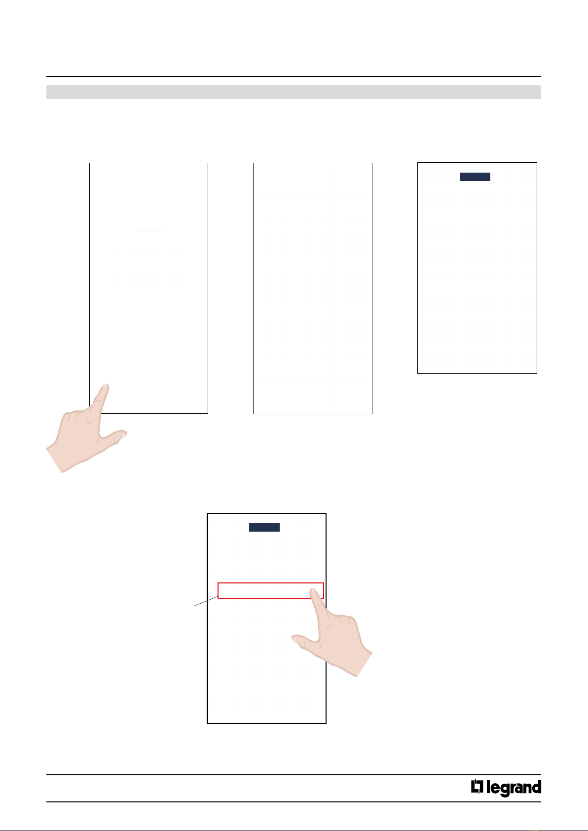
3.1 Switch-on/standby state
0 612 10
The 2 white standby LEDs come on
The green unit status LED comes on (ashing while the batteries are
charging: 24 hours max.)
Exception
Both LED indicators ashing green/yellow
- unit not addressed/lighting unit voltage present
- unit addressed/BUS voltage not present
3. OPERATION (continued)
3.2 Mains supply break/emergency operation
0 612 10
The emergency LEDs come on (45 lm)
The green unit status LED goes o
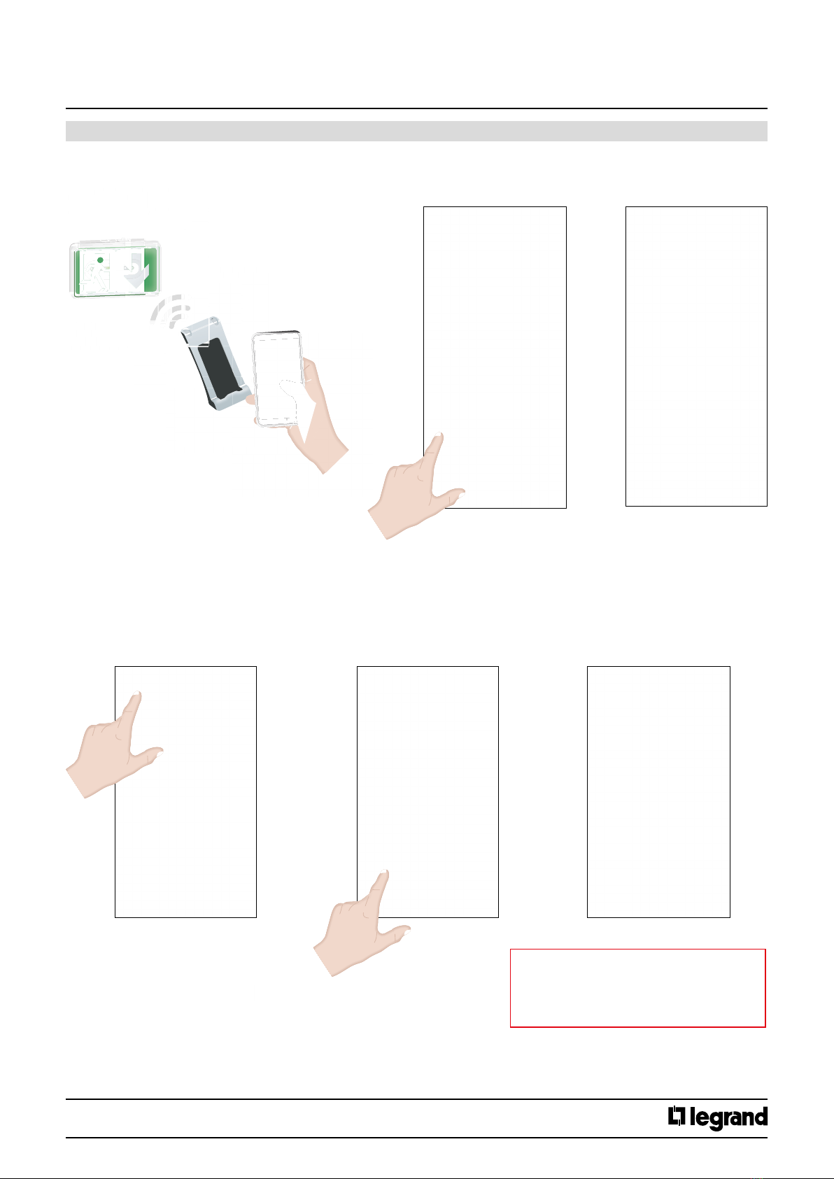
3.3 Setting to rest mode using remote controls 0 625 20/21
and 0 039 00 /01
After the normal lighting is switched o intentionally:
Pressing the O button sets the unit to rest mode to prevent the
battery discharging, in compliance with regulation EC14.
Normal lighting switched back on:
The unit automatically returns to standby.