Everlz 7700ADA User manual

7700 MultiFrame Manual
7700ADA7 Analog Video Distribution Amplifier
Revision 1.2.2
TABLE OF CONTENTS
1. OVERVIEW....................................................................................................................................1
2. INSTALLATION.............................................................................................................................2
3. SPECIFICATIONS.........................................................................................................................3
3.1. ANALOG VIDEOINPUT......................................................................................................... 3
3.2. ANALOG VIDEOOUTPUTS .................................................................................................. 3
3.3. ELECTRICAL........................................................................................................................ 3
3.4. PHYSICAL ............................................................................................................................ 3
4. STATUS LEDS..............................................................................................................................4
5. CIRCUIT DESCRIPTION...............................................................................................................4
6. JUMPERS AND USER ADJUSTMENTS.....................................................................................5
6.1. SELECTING WHETHER LOCAL FAULTS WILL BE MONITORED
BY THE GLOBAL FRAME STATUS....................................................................................... 5
6.2. SELECTING THE INPUT TERMINATION............................................................................... 5
6.3. SELECTING THE INPUT AC/DC COUPLING......................................................................... 5
6.4. GAIN ADJUSTMENT............................................................................................................. 6
Figures
Figure 1-1: 7700ADA7 Block Diagram ............................................................................................................1
Figure 2-1: 7700ADA7 Rear Panel..................................................................................................................2
Figure 6-1: LED and Jumper Locations...........................................................................................................5

7700 MultiFrame Manual
7700ADA7 Analog Video Distribution Amplifier
Revision 1.2.2
REVISION HISTORY
REVISION DESCRIPTION DATE
1.0 Original Version Jul 2005
1.1 Updated block diagram Oct 2007
1.2 General format clean up Sept 2009
1.2.1 Added information regarding input termination Apr 2010
1.2.2 Correction of Block Diagram Nov 2013
Information contained in this manual is believed to be accurate and reliable. However, Evertz assumes no responsibility for the use thereof nor for the
rights of third parties, which may be affected in any way by the use thereof. Any representations in this document concerning performance of Evertz
products are for informational use only and are not warranties of future performance, either expressed or implied. The only warranty offered by Evertz
in relation to this product is the Evertz standard limited warranty, stated in the sales contract or order confirmation form.
Although every attempt has been made to accurately describe the features, installation and operation of this product in this manual, no warranty is
granted nor liability assumed in relation to any errors or omissions unless specifically undertaken in the Evertz sales contract or order confirmation.
Information contained in this manual is periodically updated and changes will be incorporated into subsequent editions. If you encounter an error,
please notify Evertz Customer Service department. Evertz reserves the right, without notice or liability, to make changes in equipment design or
specifications.

7700 MultiFrame Manual
7700ADA7 Analog Video Distribution Amplifier
Revision 1.2.2 7700ADA7 - 1
1. OVERVIEW
The 7700ADA7 Analog Distribution Amplifier is a general purpose amplifier for distributing analog video
signals. The 7700ADA7 features one balanced input with seven outputs. The 7700ADA7 amplifier has
been designed to distribute a wide range of analog video signals. It can also distribute other pulses and
signals that are less than 2Vp-p.
The 7700ADA7 occupies one card slot and can be housed in a 1RU frame which will hold up to 3
modules, a 3RU frame which will hold up to 15 modules, a 350FR portable frame which will hold up to 7
modules or a standalone enclosure that will hold 1 module.
Features:
•75Ωor high impedance input (jumper selectable)
•High common mode range and common mode rejection ratio (CMMR)
•Gain control
•Jumper selectable AC or DC coupling
•Looping feature with external "T" connector and external termination
•Consistent input impedance if card power is lost
Balanced
Analog Input
7 Analog
Outputs
Impedance
AC/DC
Coupling
75 ?
Gain
Controls/
Indicators
FAULT
Figure 1-1: 7700ADA7 Block Diagram
7700 MultiFrame Manual
7700ADA7 Analog Video Distribution Amplifier
7700ADA7 - 2 Revision 1.2.2
2. INSTALLATION
The 7700ADA7 comes with a companion rear plate that has 8 BNC connectors. For information on
mounting the rear plate and inserting the module into the frame see section 3 of the 7700FR chapter.
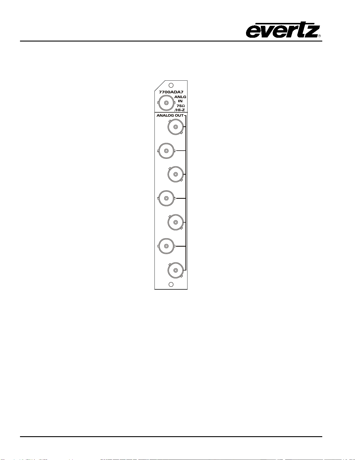
Figure 2-1: 7700ADA7 Rear Panel
ANLG IN:Input (isolated) BNC connector for analog video signals. The TERM jumper located on
the module near the back determines whether the input signal will be high impedance or
terminated with 75 ohms. (See section 6.2) The INPUT jumper located on the module
near the back determines whether the input signal will be AC or DC coupled. (See
section 6.3)
ANALOG OUT:There are seven BNC connectors with level adjusted copies of the input signal.

7700 MultiFrame Manual
7700ADA7 Analog Video Distribution Amplifier
Revision 1.2.2 7700ADA7 - 3
3. SPECIFICATIONS
Note: At the time of printing, this product has only been qualified for use with standard definition signals.
It, however, has been designed to work with high definition signals. Frequency and phase response will not
be optimized at the upper frequency range of high definition video bandwidths.
All specifications, unless indicated, measured under the following conditions:
•1 Vp-p video applied
•75 Ohm card input terminated
•AC coupled
•Gain adjusted for unity operation into 75 Ohm load
3.1. ANALOG VIDEO INPUT
Standards: Any analog video format, up to 2Vp-p and 30MHz bandwidth
Connector: BNC per IEC 61169-8 Annex A
Common Mode Range: >6Vp-p
CMRR: > 70dB to 1kHz
Signal Amplitude: 2.5Vp-p max
Impedance: 75Ohms terminated, 35kOhms Hi-Z (jumper selectable)
Coupling: AC or DC (jumper selectable)
Return Loss: >40dB to 10MHz, >30dB to 30MHz
3.2. ANALOG VIDEO OUTPUTS
Number of Outputs: 7 Per Card
Connector: BNC per IEC 61169-8 Annex A
Output Impedance: 75 Ohm
Gain Control Range: +/- 5dB
DC level (DC Coupling active) < +/- 100mV
Freq. Response: <+/-0.05dB (to 5.5MHz)
Differential Gain: <0.17 %
Differential Phase: < 0.19 deg
C/L Gain Inequality: <+/-0.1%
C/L Delay: <+/-2nsec
Output Isolation: 42dB to 10MHz, 32 dB to 30MHz
Output Return Loss: >40dB to 30MHz
Noise Performance: <-78dB RMS NTC7 weighting,
<-70dB RMS 15kHz to 5.5MHz
3.3. ELECTRICAL
Voltage: + 12VDC
Power: 4.6 Watts
3.4. PHYSICAL
Number of Slots: 1

7700 MultiFrame Manual
7700ADA7 Analog Video Distribution Amplifier
7700ADA7 - 4 Revision 1.2.2
4. STATUS LEDS
The 7700ADA7 has two LED Status indicators on the front card edge to show operational status of the
card at a glance. Figure 6-1 shows the location of the LEDs.
Two large LEDs on the front of the board indicate the general health of the module.
LOCAL FAULT: This Red LED indicates poor module health and will be On if a local input power
fault exists (i.e.: a blown fuse). The LOCAL FAULT indication can also be reported
to the frame through the FRAME STATUS jumper.
MODULE OK: This Green LED indicates good module health. It will be On when the board power
is good.
5. CIRCUIT DESCRIPTION
The input signal enters the board through a BNC with isolated ground so that balanced input processing
may be done to remove any common mode hum that may have been added to the signal and ground
shield. On-board jumpers allow you to configure the input impedance and input coupling (AC/DC).
An adjustable gain stage feeds three separate OP-Amps and drives the seven output BNC's with 75-Ohm
output impedance.

7700 MultiFrame Manual
7700ADA7 Analog Video Distribution Amplifier
Revision 1.2.2 7700ADA7 - 5
6. JUMPERS AND USER ADJUSTMENTS
MODULE STATUS
(1)7700ADA7
SFF POWER
+12V GND
J1
FRAME
STATUS
ON
OFF
GAIN ADJ
J5
75R
J4
AC DC
INPUT
J9
FLOAT
GND
SHIELD
Figure 6-1: LED and Jumper Locations
6.1. SELECTING WHETHER LOCAL FAULTS WILL BE MONITORED
BY THE GLOBAL FRAME STATUS
The FRAME STATUS jumper J1, located at the front of the module determines whether local faults (as
shown by the Local Fault indicator) will be connected to the 7700FR frame's global status bus.
FRAME STATUS: To monitor faults on this module with the frame status indicators (on the power
supply’s FRAME STATUS LED's and on the Frame's Fault Tally output) install this
jumper in the On position.
When this jumper is installed in the Off position local faults on this module will not
be monitored.
6.2. SELECTING THE INPUT TERMINATION
The input termination may be set via the card jumper J5 to either 75 Ohms (default) or Hi-Z (34k Ohms).
Set it to Hi-Z when using a "T" connector to loop the signal through several device inputs.
75 Ohms (default) is pins 2 and 3 OR Hi-Z (34K Ohms) is pins 1 and 2.
6.3. SELECTING THE INPUT AC/DC COUPLING
The input may be AC or DC (default) coupled into the input-circuitry using jumper J4. Use AC coupling in
applications when the input signal has a large (>2V) DC level. In some non-video applications that do not
have DC information (i.e. digital AES audio), AC coupling can be used to remove any DC level that may
have built up in its transmission.

7700 MultiFrame Manual
7700ADA7 Analog Video Distribution Amplifier
7700ADA7 - 6 Revision 1.2.2
6.4. GAIN ADJUSTMENT
The GAIN POT on the cards front edge allows the user to adjust the input signal level. Turning the POT
clockwise will increase the gain.
There is enough range on this control to counteract the video level error due to a
missing or double terminated coaxial connection. This will hide a frequency
response problem due to the mis-termination.
Table of contents


