Everlz 7708VT-4 User manual

7700 MultiFrame Manual
7708VT-4 Quad SDI/ASI Fiber/Coax Transmitter
Revision 1.0
TABLE OF CONTENTS
1. OVERVIEW.......................................................................................................................................... 1
2. INSTALLATION................................................................................................................................... 3
2.1. CARE AND HANDLING OF OPTICAL FIBER............................................................................ 4
2.1.1. Safety.............................................................................................................................. 4
2.1.2. Assembly......................................................................................................................... 4
2.1.3. Labeling........................................................................................................................... 4
2.1.4. Handling and Connecting Fibers..................................................................................... 5
3. SPECIFICATIONS............................................................................................................................... 6
3.1. SERIAL VIDEO INPUT ............................................................................................................... 6
3.2. OPTICAL OUTPUT..................................................................................................................... 6
3.3. DATA OUTPUT........................................................................................................................... 6
3.4. ELECTRICAL ............................................................................................................................. 6
3.5. COMPLIANCE............................................................................................................................ 7
3.6. PHYSICAL.................................................................................................................................. 7
4. STATUS INDICATORS AND DISPLAYS ........................................................................................... 8
4.1. STATUS INDICATOR LEDS....................................................................................................... 8
4.2. DOT-MATRIX DISPLAY............................................................................................................. 9
4.2.1. Displaying the Video Standard........................................................................................ 9
4.2.2. Signal BLOCK Configuration......................................................................................... 10
4.2.3. Setting the Behavior of Laser When There is No Applied Video................................... 10
4.2.4. Setting the Orientation of the Text on the Card Edge Display....................................... 10
4.2.5. Displaying the Firmware Version................................................................................... 10
5. JUMPERS AND LOCAL CONTROLS .............................................................................................. 11
5.1. SELECTING WHETHER LOCAL FAULTS WILL BE MONITORED
BY THE GLOBAL FRAME STATUS ........................................................................................ 11
5.2. CONFIGURING THE MODULE FOR FIRMWARE UPGRADES.............................................. 11
6. VISTALINK
®
REMOTE MONITORING/CONTROL........................................................................... 12
6.1. WHAT IS VISTALINK
®
?............................................................................................................... 12
6.2. VISTALINK
®
MONITORED PARAMETERS .............................................................................. 12

7700 MultiFrame Manual
7708VT-4 Quad SDI/ASI Fiber/Coax Transmitter
Revision 1.0
6.3. VISTALINK
®
CONTROLLED PARAMETERS ........................................................................... 13
6.4. VISTALINK
®
TRAPS.................................................................................................................. 13
Figures
Figure 1-1: 7708VT-4 Block Diagram....................................................................................................................2
Figure 2-1: 7708VT-4 Rear Panel.........................................................................................................................3
Figure 2-2: Reproduction of Laser Certification and Identification Label..............................................................4
Figure 4-1: Location of Status Indicators and Jumpers ........................................................................................8
Tables
Table 6-1: VistaLINK
®
Monitored Parameters.....................................................................................................12
Table 6-2: VistaLINK
®
Controlled Parameters...................................................................................................13
Table 6-3: VistaLINK
®
Traps...............................................................................................................................13

7700 MultiFrame Manual
7708VT-4 Quad SDI/ASI Fiber/Coax Transmitter
Revision 1.0
REVISION HISTORY
REVISION DESCRIPTION DATE
1.0 Original Version Feb 09
Information contained in this manual is believed to be accurate and reliable. However, Evertz assumes no responsibility for the use thereof nor for
the rights of third parties, which may be affected in any way by the use thereof. Any representations in this document concerning performance of
Evertz products are for informational use only and are not warranties of future performance, either expressed or implied. The only warranty offered
by Evertz in relation to this product is the Evertz standard limited warranty, stated in the sales contract or order confirmation form.
Although every attempt has been made to accurately describe the features, installation and operation of this product in this manual, no warranty is
granted nor liability assumed in relation to any errors or omissions unless specifically undertaken in the Evertz sales contract or order confirmation.
Information contained in this manual is periodically updated and changes will be incorporated into subsequent editions. If you encounter an error,
please notify Evertz Customer Service department. Evertz reserves the right, without notice or liability, to make changes in equipment design or
specifications.
7700 MultiFrame Manual
7708VT-4 Quad SDI/ASI Fiber/Coax Transmitter
Revision 1.0
WARNING
Never look directly into an optical fiber. Non-reversible damage to the eye can
occur in a matter of milliseconds.
"
Do not hook up the 7708VT-4 DWDM and 7708VR-4 cards directly with a short
fiber optic cable. The 7708VT-4 DWDM card produces +7dBm of power which
will damage the receiver if connected directly.
"
Do not hook up the 7708VT-4 cards that output more than -7dBm of power
(see 7708VT-4 specifications for output power of various laser types) and
7708VR-4-H high sensitivity receiver cards directly with a short fiber optic
cable. The 7708VT-4 cards that produce more than -7dBm of power will
damage the receiver if connected directly.

7700 MultiFrame Manual
7708VT-4 Quad SDI/ASI Fiber/Coax Transmitter
Revision 1.0 Page-1
1. OVERVIEW
The 7708VT-4 is a VistaLINK
®
enabled SMPTE 292M fiber or coax transmitter for SDI, DVB-ASI or SDTi
video signals. This single card combines up to four SDI, DVB-ASI or SDTi signals using Time Domain
Multiplex (TDM) technology to transmit a single SMTPTE 292M signal over fiber or coax cable. The
companion 7708VR-4 Quad SDI Receiver demultiplexes the signals and converts them back to separate
SDI video feeds.
The 7708VT-4 and companion 7708VR-4 will transparently pass incoming SDI video feeds with embedded
AES audio or any other data in the horizontal or vertical ancillary data space. Monitoring and control of
the card status and parameters is provided locally at the card edge or remotely via VistaLINK
®
.
The fiber output is available in an assortment of optical wavelengths, accommodating standard, or CWDM
transmission schemes. (See the technical specifications in section 3 for complete information).
7708VT13-4 1310 nm FP -7dBm output, suitable for distances up to 50 Km
7708VT15-4 1550 nm DFB 0dBm output, suitable for distances up to 75 Km
There are several versions with built in isolators specifically suited to coarse wave division multiplexing
(CWDM) applications. These versions all have 0dBm output and are suitable for distances up to 75 Km.
7708VT27-4 1270 nm DFB
7708VT29-4 1290 nm DFB
7708VT31-4 1310 nm DFB
7708VT33-4 1330 nm DFB
7708VT35-4 1350 nm DFB
7708VT37-4 1370 nm DFB
7708VT43-4 1430 nm DFB
7708VT45-4 1450 nm DFB
7708VT47-4 1470 nm DFB
7708VT49-4 1490 nm DFB
7708VT51-4 1510 nm DFB
7708VT53-4 1530 nm DFB
7708VT55-4 1550 nm DFB
7708VT57-4 1570 nm DFB
7708VT59-4 1590 nm DFB
7708VT61-4 1610 nm DFB
There are several versions with built in isolators specifically suited to dense wave division multiplexing
(DWDM) applications. The DWDM versions are suitable for distances >50 Km (for DWDM applications
contact factory).
7708VTDyyy-4 DWDM DFB laser output, yyy – ITU channel number
The 7708VT-4 occupies one card slot and can be housed in either a 1RU frame, which will hold up to
three modules, or a 3 RU frame, which will hold up to 15 modules.

7700 MultiFrame Manual
7708VT-4 Quad SDI/ASI Fiber/Coax Transmitter
Page-2 Revision 1.0
Features:
•Single card TDM multiplexer for four synchronous or asynchronous 270Mb/s SDI, SDTi or DVB-
ASI video signals
•Output compatible with SMPTE 292 reclocking devices
•Signal transport over fiber uninterrupted by loss of any SDI, SDTi or DVB-ASI input feed
•Transparently passes embedded AES or any other data in the horizontal or vertical ancillary data
space
•Comprehensive signal and card status monitoring via four digit card edge display or remotely
through SNMP and VistaLINK
®
•Occupies one card slot and can be housed in either a 1RU frame which will hold up to 3 modules,
a 3RU frame which will hold up to 15 modules, 3RU portable frame that holds up to 7 modules or a
standalone frame which will hold 1 module
•VistaLINK
®
capability is available when modules are used with the 3RU 7700FR-C or 350FR
portable frame and a 7700FC VistaLINK
®
Frame Controller module in slot 1 of the frame
•Fully hot-swappable from front of frame with no fiber disconnect/reconnect required
•Supports single-mode and multi-mode fiber optic cable
•Optical output wavelengths of 1310nm, 1550nm, and up to sixteen CWDM wavelengths (ITU-T
G.694.2 compliant)
•DWDM wavelengths (ITU-T G.694.1 compliant) also available
•SC/PC, ST/PC, FC/PC connector options
TDM
MUX
VistaLINK
®
Interface
SDI Video
Input
SDI Video
Input
SDI Video
Input
SDI Video
Input
Input
Stage
Input
Stage
Input
Stage
Input
Stage
Optical
Control Local
Indication
Control/
Indication
Fiber
Output
Optical
Transmitter
Coax
Output
Figure 1-1: 7708VT-4 Block Diagram
7700 MultiFrame Manual
7708VT-4 Quad SDI/ASI Fiber/Coax Transmitter
Revision 1.0 Page-3
2. INSTALLATION
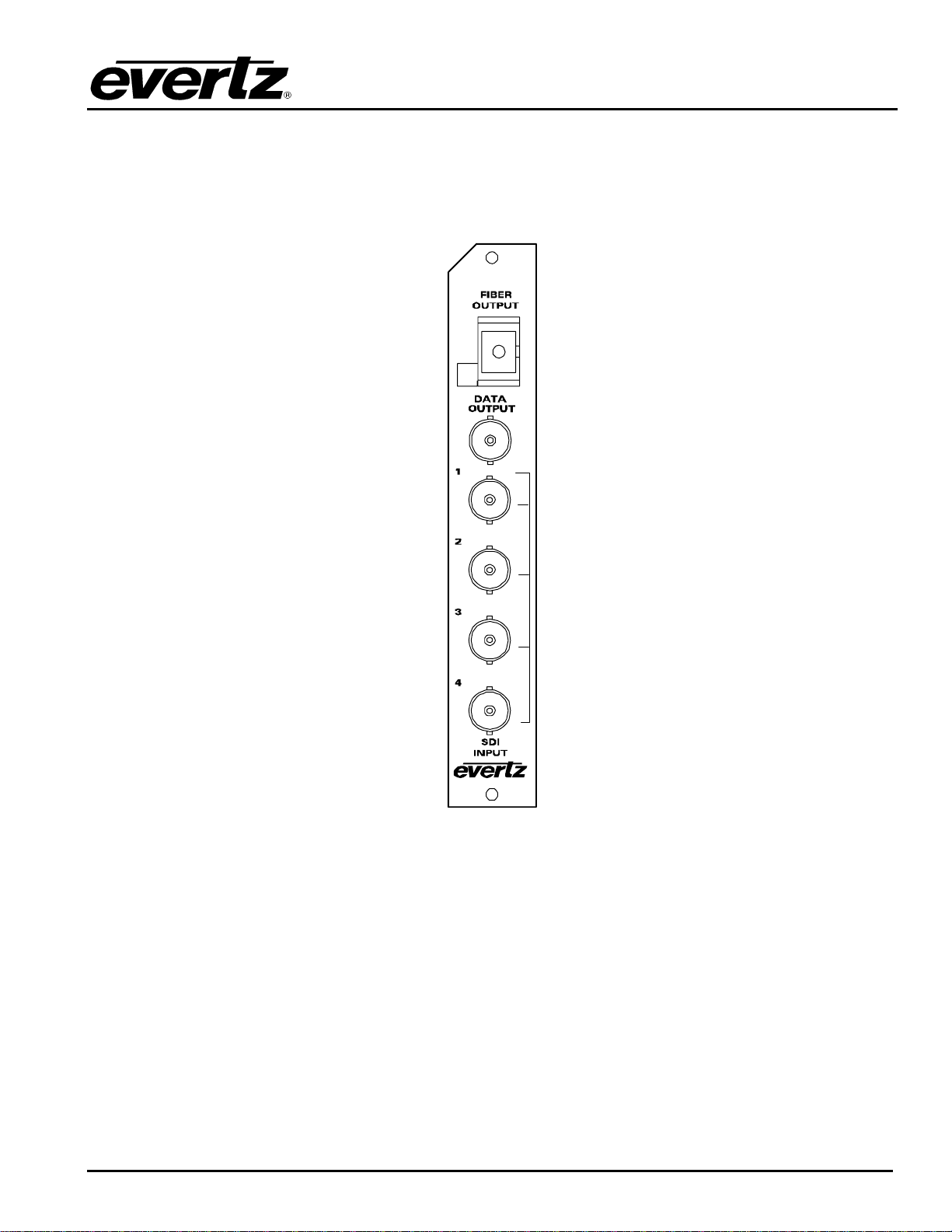
The 7708VT-4 comes with a companion rear plate that has five BNC connectors and one SC/PC (shown),
ST/PC or FC/PC optical connector. For information on mounting the rear plate and inserting the module
into the frame see section 3 of the 7700FR chapter.
7708VT-4
Figure 2-1: 7708VT-4 Rear Panel
SDI INPUT: Four independent BNC input connectors for 10-bit serial digital video signals compatible
with the SMPTE 259M, DVB-ASI or SMPTE 305M standards. These inputs provide adaptive
compensation for up to 250m of industry standard Belden 8281 cable, at 270Mb/s.
OPTICAL OUTPUT: Output SC/PC, SC/PC with cover (shown), ST/PC or FC/PC female connector. This
optical output contains the four input SDI video signals. Any ancillary data (e.g. embedded
audio, closed captioning, etc) present in the input SDI video stream prior to multiplexing is
transparently passed through to the output.
DATA OUTPUT: Output BNC female connector. This coax SMPTE 292M output contains the four input
SDI video signals. Any ancillary data (e.g. embedded audio, closed captioning, etc) present in
the input SDI video stream prior to multiplexing is transparently passed through to the output.
7700 MultiFrame Manual
7708VT-4 Quad SDI/ASI Fiber/Coax Transmitter
Page-4 Revision 1.0
2.1. CARE AND HANDLING OF OPTICAL FIBER
2.1.1. Safety
!
CLASS 1 LASER PRODUCT
Background colour: yellow
Triangular band: black
Symbol: black
2.1.2. Assembly
Assembly or repair of the laser sub-module is done only at Evertz facility and performed only by qualified
Evertz technical personnel.
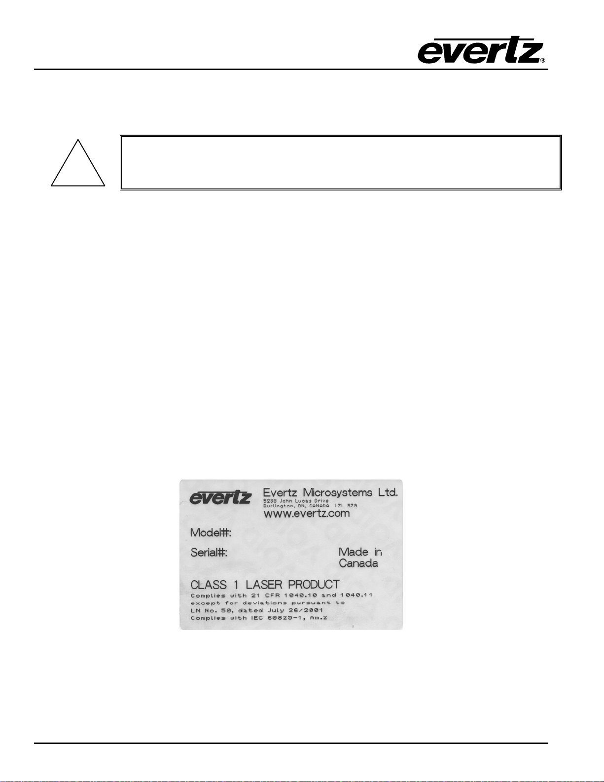
2.1.3. Labeling
Certification and Identification labels are combined into one label. As there is not enough room on the
product to place the label, it is reproduced here in the manuals.
•There is no date of manufacture on this label as it can be traced by bar code label placed on the
Printed circuit board of each Evertz plug-in module
•The Model number is one of: 7708VT13-4, 7708VT15-4,
7708VTxx-4, (xx = 27, 29, 31, 33, 35, 37, 43, 45, 47, 49, 51, 53, 55, 57, 59, 61)
7708VTDyyy-4 (Dyyy represents ITU Grid Channel: D200, D210, D220, D230, D240, D250, D260,
D270, D280, D290, D300, D310, D320, D330, D340, D350, D360, D370, D380, D390, D400,
D410, D420, D430, D440, D450, D460, D470, D480, D490, D500, D510, D520, D530, D540,
D550, D570, D580, D590, D600)
Figure 2-2: Reproduction of Laser Certification and Identification Label

7700 MultiFrame Manual
7708VT-4 Quad SDI/ASI Fiber/Coax Transmitter
Revision 1.0 Page-5
2.1.4. Handling and Connecting Fibers
"
Never touch the end face of an optical fiber. Always keep dust caps on optical fiber
connectors when not connected and always remember to properly clean the optical
end face of a connector before making a connection.
The transmission characteristics of the fiber are dependent on the shape of the optical core and therefore
care must be taken to prevent fiber damage due to heavy objects or abrupt fiber bending. Evertz
recommends that you maintain a minimum bending radius of 5 cm to avoid fiber-bending loss that will
decrease the maximum attainable distance of the fiber cable. The Evertz fiber optic modules come with
cable lockout devices, to prevent the user from damaging the fiber by installing a module into a slot in the
frame that does not have a suitable I/O module. For further information about care and handling of fiber
optic cable see section 3 of the Fiber Optics System Design section of this manual binder.

7700 MultiFrame Manual
7708VT-4 Quad SDI/ASI Fiber/Coax Transmitter
Page-6 Revision 1.0
3. SPECIFICATIONS
3.1. SERIAL VIDEO INPUT
Standard: SMPTE 259M-C, SMPTE 305M, DVB-ASI
Number of Inputs: 4 independent SDI or DVB-ASI, 270Mb/s signals
Connector: 4 BNC per IEC 61169-8 Annex A
Return Loss: > 15dB up to 270Mb/s
3.2. OPTICAL OUTPUT
Number of Outputs: 1
Output Standard: SMPTE 292M (not compatible with 7707VR-4)
Connector: Female SC/PC, ST/PC or FC/PC
Return Loss: > 14 dB
Rise and Fall Time: 200 ps nominal
Wide Band Jitter: < 0.20UI
Fiber Size: 9 µm core / 125 µm overall
Wavelengths:
Standard: 1310nm
CWDM: 1270nm to 1610nm (See ordering information)
DWDM: ITU channel 20 to 60 wavelengths (ITU-T G.694.1 compliant)
Output Power:
1310nm FP: -7dBm ±1dBm
CWDM: 0 dBm ±1dBm
DWDM: +7dBm ±1dBm
3.3. DATA OUTPUT
Number of Outputs: 1
Output Standard: SMPTE 292M
Connector: BNC per IEC 61169-8 Annex A
Impedance: 75 Ωnominal
Signal Level: 800mV nominal
DC Offset: 0V ±0.5V
Rise/Fall Time: <270ps nominal
Overshoot: <10% of amplitude
Return Loss: >12dB up to 1.5GHz
Wideband Jitter: <0.2UI (reclocked)
3.4. ELECTRICAL
Voltage: +12VDC
Power: 10 Watts (Non DWDM)
13 Watts (DWDM)

7700 MultiFrame Manual
7708VT-4 Quad SDI/ASI Fiber/Coax Transmitter
Revision 1.0 Page-7
3.5. COMPLIANCE
Electrical Safety: CSA Listed to UL 60065-03, IEC 60065
Complies with CE Low voltage Directive
Laser Safety: Class 1 laser product
Complies with 24 CFR 1040.10 and 1040.11
Complies with IEC 60825-1
EMI/RFI: Complies with FCC Part 15, Class A, EU EMC directive
3.6. PHYSICAL
350FR, 7700FR-C, 7800FR, 7701FR, or S7701FR frame mounting:
Number of slots: 1
7700 MultiFrame Manual
7708VT-4 Quad SDI/ASI Fiber/Coax Transmitter
Page-8 Revision 1.0
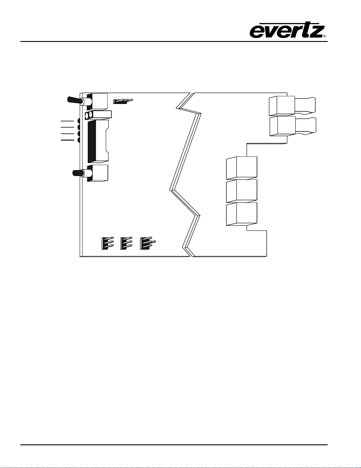
4. STATUS INDICATORS AND DISPLAYS
The 7708VT-4 has 6 LED Status indicators and a 4 digit alphanumeric display on the front card edge to
show operational status of the card at a glance. The card edge pushbutton is used to select various
displays on the alphanumeric display. Figure 4-1 shows the locations of the indicators and pushbutton.
FRAME STATUS
ON/OFF
/ MODULE OK
LOCAL FAULT
Video 1 Present
LOCAL/REMOTE
COM
RUN/UPGRADE
Video 2 Present
Video 3 Present
Video 4 Present
Figure 4-1: Location of Status Indicators and Jumpers
4.1. STATUS INDICATOR LEDS
LOCAL FAULT: This Red LED indicates poor module health and will be On during the absence of a
valid input signal, if a laser fault exists, or if a local input power fault exists (i.e.: a
blown fuse). The LOCAL FAULT indication can also be reported to the frame
through the FRAME STATUS jumper.
MODULE OK: This Green LED indicates good module health. It will be On when a valid input
signal is present, and the laser and board powers are good.
On the 7708VT-4, there are four small LEDs on the back of the board that indicate the presence of video
signals.
VIDEO 1 PRESENT: This Green LED indicates the presence of a valid signal on the Video 1 input.
VIDEO 2 PRESENT: This Green LED indicates the presence of a valid signal on the Video 2 input.
VIDEO 3 PRESENT: This Green LED indicates the presence of a valid signal on the Video 3 input.
VIDEO 4 PRESENT: This Green LED indicates the presence of a valid signal on the Video 4 input.

7700 MultiFrame Manual
7708VT-4 Quad SDI/ASI Fiber/Coax Transmitter
Revision 1.0 Page-9
4.2. DOT-MATRIX DISPLAY
Additional signal and card status monitoring is provided via the 4-digit dot-matrix display located on the
card edge. The card-edge pushbutton is used to select which data is being displayed in the alphanumeric
display. Each time the pushbutton is pressed, the display advances to the next available display. A
message indicating what display mode is active is shown for one second. After one second without the
pushbutton being pressed, the selected display data is shown.
The following display messages indicate what is being displayed.
CH 1 Video Standard in Use On Channel 1.
CH 2 Video Standard in Use On Channel 2.
CH 3 Video Standard in Use On Channel 3.
CH 4 Video Standard in Use On Channel 4.
PSWD Sets/configures password for enabling/disabling video channels.
LASR Sets Laser to Continuous or Discontinuous mode.
DISP Sets the orientation of the text displayed on the card edge.
VER Displays the present Firmware version.
4.2.1. Displaying the Video Standard
The 7708VT-4 detects the Video standards of the signal present at its input.
CH1-CH4
VSD
N270
P270
ASI
NONE
UNKN
To display the Video Standard, press the pushbutton and actuate the
toggle switch until CH 1, CH 2, CH 3 or CH 4 message is shown on
the display. Enter specific channel menu by pressing pushbutton when
specific channel is shown. Then toggle to VSD and press the pushbutton
again. After one second the detected video standard will be shown. The
following list describes possible displays and their meaning.
N270 SMPTE 259M-C, 270 Mb/s 4:2:2 Component 525 line, 4:3 or
SMPTE 305M.
P270 SMPTE 259M-C, 270 Mb/s 4:2:2 Component 625 line, 4:3 or
SMPTE 305M.
ASI Indicates DVB-ASI Signal at Input.
NONE Indicates that no valid output signal is present.
UNKN 270Mb/s unrecognized format.

7700 MultiFrame Manual
7708VT-4 Quad SDI/ASI Fiber/Coax Transmitter
Page-10 Revision 1.0
4.2.2. Signal BLOCK Configuration
PSWD
PWSL
VCH1 Press the pushbutton and select the PSWD option. Actuate the toggle
switch to achieve the correct code number (Factory Default = 7154).
PWSL Store a new passcode (0-9999) required for BLOCK
configuration. This menu is not available without entering the
correct passcode.
VCH1 EN / DIS. When Disabled the data received on the fiber link
intended for output 1 is not output. This menu item is not
modifiable without entering the correct passcode, though its
current state is viewable.
4.2.3. Setting the Behavior of Laser When There is No Applied Video
On the 7708VT-4 the LASR display allows you to set the behavior of the laser transmitter when there is no
video signal applied to the coaxial video inputs.
LASR
CONT
DISC CONT The laser will transmit continuously regardless of whether there
are valid input video signals present on the coaxial inputs of the
7708VT-4.
DISC The laser will turn off when there is no recognizable video on
any of the coaxial inputs. EN / DIS. When Disabled the data
received on the fiber link intended for output 1 is not output.
This menu item is not modifiable without entering the correct
passcode, though its current state is viewable.
4.2.4. Setting the Orientation of the Text on the Card Edge Display
On the 7708VT-4 the DISP display allows you to set a horizontal or vertical orientation for the card edge
display messages. After one second the display will show a message indicating the current orientation of
the display. When this message is showing, press the pushbutton to change the orientation of the display.
DISP
HORZ
VERT HORZ Horizontal display used when the module is housed in the 1
rack unit 7701FR frame or the stand-alone enclosure.
VERT Vertical display used when the module is housed in the 3-rack
unit 7700FR frame.
4.2.5. Displaying the Firmware Version
The VER display shows the firmware version and build number of the 7708VT-4 firmware. The message
will scroll across the display.
For example: VER 1.0 BLD 067

7700 MultiFrame Manual
7708VT-4 Quad SDI/ASI Fiber/Coax Transmitter
Revision 1.0 Page-11
5. JUMPERS AND LOCAL CONTROLS
Several jumpers, located at the front of the module are used to preset various operating modes. Figure
4-1 shows the locations of the jumpers.
5.1. SELECTING WHETHER LOCAL FAULTS WILL BE MONITORED
BY THE GLOBAL FRAME STATUS
The FRAME STATUS jumper determines whether local faults (as shown by the Local Fault indicator) will
be connected to the 7700FR frame's global status bus.
FRAME STATUS: To monitor faults on this module with the frame status indicators (on the Power
Supply FRAME STATUS LED's and on the Frame's Fault Tally output) install this
jumper in the On position. (default)
When this jumper is installed in the Off position local faults on this module will not
be monitored.
5.2. CONFIGURING THE MODULE FOR FIRMWARE UPGRADES
UPGRADE: The UPGRADE jumper is used when firmware upgrades are being done to the
module. For normal operation it should be installed in the RUN position. See the
Upgrading Firmware section of this manual for more information.
To upgrade the firmware in the module unit pull it out of the frame. Move the
UPGRADE jumper into the UPGRADE position. Install the Upgrade cable provided
(located in the vinyl pouch in the front of this manual) onto SERIAL header at the
card edge. Re-install the module into the frame. Run the upgrade as described in
the Upgrading Firmware section of this manual. Once the upgrade is completed,
remove the module from the frame, move the UPGRADE jumper into the RUN
position, remove the upgrade cable and re-install the module. The module is now
ready for normal operation.

7700 MultiFrame Manual
7708VT-4 Quad SDI/ASI Fiber/Coax Transmitter
Page-12 Revision 1.0
6. VISTALINK
®
REMOTE MONITORING/CONTROL
6.1. WHAT IS V
ISTA
LINK
®
?
VistaLINK
®
is Evertz’s remote monitoring and configuration platform which operates over an Ethernet
network using Simple Network Management Protocol (SNMP). SNMP is a standard computer network
protocol that enables different devices sharing the same network to communicate with each other.
VistaLINK
®
provides centralized alarm management, which monitors, reports, and logs all incoming alarm
events and dispatches alerts to all the VLPro Clients connected to the server. Card configuration through
VistaLINK
®
PRO can be performed on an individual or multi-card basis using simple copy and paste
routines, which reduces the time to configure each module separately. Finally, VistaLINK
®
enables the
user to configure devices in the network from a central station and receive feedback that the configuration
has been carried out.
There are 3 components of SNMP:
1. An SNMP manager, also known as a Network Management System (NMS), is a computer running
special software that communicates with the devices in the network. Evertz VL-Fiber demo Manager
graphical user interface (GUI), third party or custom manager software may be used to monitor and
control Evertz VistaLINK
®
enabled fiber optic products.
2. Managed devices (such as 7708VT-4 and 7708VR-4 cards), each with a unique address (OID),
communicate with the NMS through an SNMP Agent. Evertz VistaLINK
®
enabled 7700 series modules
reside in the 3RU 7700FR-C MultiFrame and communicate with the manager via the 7700FC
VistaLINK
®
frame controller module, which serves as the Agent.
3. A virtual database, known as the Management Information Base (MIB), lists all the variables being
monitored, which both the Manager and Agent understand. Please contact Evertz for further
information about obtaining a copy of the MIB for interfacing to a third party Manager/NMS.
For more information on connecting and configuring the VistaLINK
®
network, see the 7700FC Frame
Controller chapter.
6.2. V
ISTA
LINK
®
MONITORED PARAMETERS
The following parameters can be remotely monitored through the VistaLINK
®
interface.
Parameter Description
Video 1, 2, 3, 4 Standard A range of values describing the detected video standard
Table 6-1: VistaLINK
®
Monitored Parameters

7700 MultiFrame Manual
7708VT-4 Quad SDI/ASI Fiber/Coax Transmitter
Revision 1.0 Page-13
6.3. V
ISTA
LINK
®
CONTROLLED PARAMETERS
The following parameters can be remotely controlled through VistaLINK
®
interface.
Parameter Description
Change Password Allows user to change password that is needed in
order to enable/disable video channels
Video 1, 2, 3, 4 Channel Enable Enables or disables a video channel
Table 6-2: VistaLINK
®
Controlled Parameters
6.4. V
ISTA
LINK
®
TRAPS
The following traps can be remotely monitored through VistaLINK
®
interface.
Trap Description
Video 1, 2, 3, 4 Not Present Triggers when there is a loss of video signal
Video 1, 2, 3, 4 EDH Errors Present Triggers when there is a EDH error present in video
signal
Laser Not Ok Triggers on laser fault condition
Table 6-3: VistaLINK
®
Traps

7700 MultiFrame Manual
7708VT-4 Quad SDI/ASI Fiber/Coax Transmitter
Page-14 Revision 1.0
This page left intentionally blank
Table of contents
Other Everlz Transmitter manuals


