Rain Bird TBOS User manual

™
Technotes
TBOS MANAGER
. . . . . . . . . . . . . . . . . . . . . . . .P. 01
. . . . . . . . . . . . . . . . . . . . . . . .P. 14
. . . . . . . . . . . . . . . . . . . . . . . .P. 27
. . . . . . . . . . . . . . . . . . . . . . . .P. 40
. . . . . . . . . . . . . . . . . . . . . . . .P. 53
. . . . . . . . . . . . . . . . . . . . . . . .P. 66
F
GB
D
E
NL
P
TBOS Manager couv DER 5/11/04 14:49 Page 2

GB
14
PRELIMINARY INFORMATION
Rain Bird thanks you for choosing the TBOS system. This new universal
field transmitter can program all types of modules : TBOS Radio+,
VRM-1+, and FS1. You can use it with all TBOS Systems: TBOS
Infrared, TBOS Radio, TBOS MANAGER II.
IMPORTANT :The new Universal TBOS Field Transmitter features
2 modes of operation: Standard (Radio and Infrared) or TBOS Manager II.
A: Standard Mode: (Infrared or Radio)
You can directly set the program on the field transmitter and download
it in 2 ways:
1. Infrared download. Use the pre-installed cord.
2. Radio download
B: TBOS Manager Mode
The program is set up on a PC using the TBOS Manager II Software.
You transmit the programs to the modules through radio
transmission only using the Universal Field Transmitter in TBOS
Manager mode.
IMPORTANT :
You must select the operation mode on your field transmitter before
using it.
To do this, you have to perform the following steps:
EXAMPLE:
You are in the Standard mode and you want to change to the TBOS
Manager mode.
●Press simultaneously on and
●The screen displays a blinking for TBOS Manager
a) Confirm by pressing on , The screen will display
during several seconds. You are now in the TBOS
Manager mode.
b) If you want to stay in the Standard mode, cancel the above operation
by pressing on . The screem will be displayed
during several seconds.
You remain in the Standard mode.
To change from TBOS Manager Mode to the Standard mode, follow
exactly the same procedure.
ATTENTION :
the choice of the mode is not definitive. You can change modes
when you want. But the data of the mode you leave will be
definitively lost.
TBOS Manager Anglais new der 5/11/04 12:08 Page 1

GB
15
TBOS
Control
Module
UNIK
Control
Module
New version
Console
TBOS™
MANAGER
(old version)
Relay
Underground Rain Shutoff
device with ON/OFF switch
TBOS Manager is a management system designed to program battery
powered TBOS Control Modules by radio. The system consists of:
TBOS Manager software operating in a Windows 95, Windows 98 or
Windows NT environment
• Radio Transmission Interface device connected to a PC Serial port
for old version or to PC USB port for the nex version (Date Code:
Oct 2003)
• 1,2,4 and 6-station Control Modules
• TBOS Radio Interface Unit with a date code indicating a
manufacturing date after February, 1998 or a VRM-1+ Radio Module
• Water Volume consumption supervisor: FS1
• TBOS Universal Field Transmitter to program Modules equipped with
a TBOS Radio+ Interface, VRM-1+ modules.
TBOS MANAGER II
Interface
Radio transmission
Device connected
to a PC
A TBOS™ MANAGER II SYSTEM
1. SYSTEM COMPONENTS
2. OPTIONS
VRM-1
FS-1
RSD-BEx
TBOS Radio
Interface with
a date code
after Feb. 1998
Tbos™
field
Transmitter
TBOS
Latching
solenoid
TBOS Manager Anglais new der 5/11/04 12:08 Page 2

1• Select program (A,B or C)
2• Transmission problem
3• Now Transmissing
4• Low battery indicator:
- in the transmitter if the icon appears
when the key is pressed to turn on
the LCD
- in the TBOS module if the icon appears
during program transmission
5• ON/OFF mode
6• Manual station (STA) start or manual
Program/Cycle (CYC) start
A• Increase adjustment key
B• Decrease adjustment key
C• Program/cycle selection key (A, B, or C)
D• Move to next function key
E• Key to work within a function
F• Radio Transmission key transmits
program to Control Modules equipped
with a Radio+ Interface or to VRM-1+
Radio Modules.
G• Key for the Scanner feature
GB
16
• The Field Transmitter can program an unlimited number of Control
Modules equipped with Radio+ Interface Units, or VRM-1+ radio
modules.
• The Radio Interface is simply snapped onto the Control Module.
• The average radio transmission range between the Field Transmitter
and the Radio Interface is 0,5 to 200m. Distance varies depending
on site conditions.
• Automatic synchronization of current time and day when the computer
transmits the programs to the Field Transmitter.
• Automatic reset of current time and day when program is transmitted
from the field transmitter to the Control Module.
• LCD automatically turns off after 1 minute if transmitter is not being
used to prolong battery life.
• Battery life: 1 season with 1 top grade 9V battery such as Varta or
equivalent. Battery not included.
• Low battery indicator (TBOS Universal Field Transmitter and TBOS
Control Module).
• Maximum storage and operating temperature: 55°C
• Maximum system operating pressure : 10 bar.
3. LCD SCREEN ICONS
4. SPECIFICATIONS
6
45
3
2
5. KEYPAD
FG
A
E
D
C
B
1
3
TBOS Manager Anglais new der 5/11/04 12:08 Page 3

17
You do not manually enter any programs into the Field Transmitter.
All programs are transmitted from your computer which is equipped
with TBOS Manager II software and a Radio Transmission Interface
to download the programs by radio into the TBOS Universal Field
Transmitter. See TBOS Manager II software manual.
Step 1 :
Enter your Control Module programs into the computer with the TBOS
Manager II software. (See TBOS Manager II Software Manual)
Step 2 :
Use the TBOS Manager Radio Transmission Interface Device to download
the programs by radio from the computer into the TBOS Universal Field
Transmitter in the Manager mode. (See TBOS Manager II Software Manual).
Step 3 :
Then go to the sites. Use the Field Transmitter to transmit the program
into each Control Module equipped with Radio+ Interface or VRM-1
Radio Module or FS1 by radio. You should be near the units when you
transmit.
B. OPERATION OVERVIEW
GB
TBOS Manager Anglais new der 5/11/04 12:08 Page 4

GB
18
2• Check that you are in the TBOS MANAGER Mode.
Refer to the “preliminary Information” section at the
beginning of the Instruction Manual.
1• Install a battery in the Field Transmitter
C. SYSTEMSTART
Ref: 6LR61 (6AM6)
(Varta or equivalent)
Install the battery
compartment cover and
secure it
3• Enter a 2-number code in the Field Transmitter.
This code differentiates Transmitters that are used on different sites.
Important: the code (01 to 99) must be the same code that you entered
in the TBOS Manager II software.
a) Press simultaneously the and keys.
The following screen appears.
b) Use or to enter the code
c) Press
Example: you have entered "12" in your software
for this transmitter. Enter the same code in your
field transmitter.
Note: You do not need to set current time because the transmitter
automatically receives the time of day from the computer during the
downloading phase.
Install the battery
Unscrew the battery compartment
cover and remove it
TBOS Manager Anglais new der 5/11/04 12:08 Page 5

GB
19
D. IDENTIFICATION MODE
The transmission of the data is done thanks to a radio communication system.
Each unit (TBOS RADIO+ Interface, VRM-1+, FS-1) must be
identified. If, for example, 2 control modules equipped with radio interface
units or 2 VRM-1+ radio modules are near each other, each unit must
have its own identification code to avoid communication interference.
This function is used to identify the modules by assigning the site number
and control module number with a 4-digit number.
This allows the transmitter to register the city code in the software.
The transmitter is now ready to transmit to the control modules.
Each Radio+ unit (TBOS Radio+ Interface, VRM-1+) must receive a
4-digit identification code.
This 4-digit identification code contains :
•
2 digits which are the digits of the city. This 2-digit code is common
to all TBOS Modules managed by the same field transmitter.
•
2 digits which are the radio module code (TBOS Radio+ Interface
or VRM-1+). This code varies from one unit to another.
Here are the steps to follow to identify your TBOS Radio+ interface, VRM-
1+, or FS1.
1- Download from the PC to your TBOS Manager II Field transmitter
the programs of all your radio units: TBOS Radio + Interface, or VRM-
1+ or FS1 (see our software). Then the Field transmitter is ready to
identify the radio units.
The following steps must be performed for each unit one at a time.
2- Install the battery inside the Radio+ modules
IMPORTANT : Install the battery in only one radio units. Then download
the identification code into that radio module. Do not install the batteries
in all the radio units at the same time.
Method 1 :
(Quicker)
1. Repeatedly press the key on your Field transmitter to
display the “—Pr—“ screen. For example, “02Pr02”.
2. Press the key to display the 4-digit identification number
of your radio unit: TBOS Radio+ Interface or VRM-1+ or FS1. In our
example 0102.
3. Press the key to transmit the 4-digit identification code
to the radio unit.
Method 2 :
1. Repeatedly press the key to display the “00Site”
screen.
2. Select the number of the site that you have previously set up in
your PC Software by pressing the or key.
“01Site” in our example.
3. Press the key and select the number of the radio unit
by pressing the and keys. “02 Modu” in our example.
TBOS Manager Anglais new der 5/11/04 12:08 Page 6

2.1•If the LCD screen is blank, press .
2.2•Important: you must enter an identification code in the Radio unit
before transmitting a program. (See paragraph "D. Identification Mode").
E. TRANSMISSION
Note: the Field Transmitter is automatically synchronized with the computer
during transmission. Both have the same current time.
Place your Field Transmitter near the Radio Transmission Interface connected
to your computer. Start transmitting the desired programs stored in
the software (see TBOS Manager II software manual). The computer
downloads the programs into the Field Transmitter. The transmission
process is displayed on your computer screen and on the transmitter
LCD. You will hear 3 "beeps" when transmission begins.
Your transmitter will display the programs as they are transmitted.
Example: if you transmit the programs for 3 Control Modules to your
Field Transmitter, the LCD will display the following screens in sequence:
This means that the programs are now stored in the Field Transmitter.
The computer will confirm the successful transmission of the programs.
GB
4. Press the key to transmit the 4-digit identification code
to the radio unit.
You can now program the Control Modules.
IMPORTANT :
1. Don't forget the Control Module identification codes. It is best to
write them down somewhere. You can enter them on the site plan in
the software or write them on the Control Modules equipped with a
Radio+ Interface or a VRM-1.
1. DOWNLOAD FROM THE PC TO THE FIELD
TRANSMITTER
2. PROGRAM TRANSMISSION TO THE CONTROL
MODULES
20
2.During step 4, the TBOS Radio Field Transmitter performs the Scanner
function (see §H) before sending the identification code. This feature
avoids having two radio+ interface units with the
same identification code. If there is no other interface
with the same selected identification code,
the Field Transmitter will display the following screen
which means that the transmission has been
successful.
If another radio interface already has the same
identification code, several “beeps” will be heard.
Then the Field Transmitter will cancel the
identification process and will display:
TBOS Manager Anglais new der 5/11/04 12:08 Page 7

GB
21
As the programs are transmitted, the number to the right of "Pr" will
decrease. After all the programs have been transmitted to a given control
Module, "Pr00" will be displayed.
Example: 02 Pr 00 means that there were 2 programs to transmit.
None remain to be transmitted.
Note: To display the other control modules to which programs must
be transmitted, press when the 02 Pr
02 type screen is displayed.
Example: "0102" will appear. Each control
module is displayed with a 4-digit number defined
by the software. The first 2 digits indicate the
site number. The last 2 numbers indicate the
control module number. In the example, site
Nr.1, control module Nr. 2.
Important: If the blinking low battery icon is displayed on the LCD
for 30 seconds during program transmission, replace the 9V battery
in the TBOS control module. The low battery icon is used only for TBOS
control modules.
2.3•Repeatedly press until this type of screen is displayed.
You cannot transmit a program unless this type
of screen is displayed. In this example,
2 programs have been transmitted.
2.4•Press to the radio modules. This display and
will appear for several seconds. Transmission is completed.
F . USE OF A FS1
Important : The FS1 must always be used with a water meter with
built-in dry-contact impulse sensor. We recommend using a
10l/impulse water meter .
1. IDENTIFICATION
Like a TBOS Radio+ interface ot a VRM-1+, you must assign a 4-digit
identification number. This 4-digit code consists of:
• The first 2 digits are the code of the city.
• The second 2 digits are the radio unit code
However you must decide between 2 possibilities:
1- If the FS1 is used as a flow supervisor, then the 2-digit radio code
is always 49. This code is automatically set up by the TBOS Manager
II Software.
2- If the FS1 is used as a control module based on water volume
consumption, then you have to select a 2-digit radio code from
1 up to 48 like a TBOS Radio+ interface or a VRM-1+. See § “
Identification Mode”
TBOS Manager Anglais new der 5/11/04 12:08 Page 8

GB
22
If there is an alarm, the screen displays:
2. DOWNLOAD TO A FS1
See § “E- Transmission
3. FS1 MONITORING
If you are close to a FS1, you can monitor it in order to upload any
alarms and the total water consumption.
1.repeatedly press the
key to access the following screen.
2. Press the key. Then the TBOS Manager II Filed transmitter
automatically communicates with the FS1 module closest to the user.
The Field transmitter automatically uploads the following data:
• total water consumption
• Any alarms in case of excessive flow.
This screen means that FS1 #49 on site #3 has an alarm.
You have 2 possibilities:
a) You can acknowledge the alarm by pressing . This
means that you cancel all the alarms detected by the FS1 and that
the FS1 will continue operating normally.
Important: We recommend checking your installation (possible leakage)
or increasing the maximum volume of water you have programmed
in your TBOS Manager Software.
b) You prefer not to acknowledge the alarm. Then you press the key.
This means that your installation will keep watering only if you have
selected the “ Auto restart “ in your software or will stop if you have
not made this selection.
To upload the total water consumption into your computer, please refer
to your TBOS Manager II instruction manual.
TBOS Manager Anglais new der 5/11/04 12:08 Page 9

STA
1.1 Repeatedly press until the module screen appears. See
example below.
1.2 Enter the Radio+ Interface identification code
by pressing or .
1.3 Then repeatedly press until the screen below appears.
1.4 Repeatedly press the key until the desired station number
appears. The station number appears at the left.
(Example: station 1).
1.5 Press . Irrigation will start after 10 seconds.
If you wish to stop watering before the programmed time is up, press
the key.
Important !
The next 3 functions override all others. This means that any
program currently running will be suspended to permit the use
of the manual functions. Before carrying out a manual start,
make sure a run time (at least 1 minute) has been programmed and
that the Control module is in the irrigation "ON" mode (no X on the
sprinkler).
G. MANUAL FUNCTIONS
GB
23
1. MANUAL SINGLE STATION START
TBOS Manager Anglais new der 5/11/04 12:08 Page 10

The field transmitter has a function which can place the control module
in the "OFF" mode. The default mode is "ON" which allows the programmed
watering to take place. You can prevent watering (rainy weather shutoff)
without changing the programmed cycles.
”OFF” Mode
1. First enter the Radio+ interface identification code.
2. To prevent irrigation press the key.
A cross will appear on the sprinkler.
”ON” Mode
1. To return to the irrigation mode, repeatedly press until the
screen with the X on the sprinkler appears.
2. Now press the key. The cross disappears.
(used only on 2 or 4 station modules)
Remember that a program/cycle consists of all stations assigned to
the same program operating in sequential order.
2.1 First enter the Radio Interface+identification code.
2.2 Repeatedly press the key until this screen appears.
2.3 Select the program/cycle you wish to start with the ABC key.
Your selection is displayed as "Prog A", "Prog B" or "Prog C".
Prog A =lawn, Prog B =Shrubbery, Prog C =Tree in the software.
2.4 Press the key to start the cycle. After 10 seconds, irrigation
will start.
The stations assigned to the program will operate in sequence one
after the other until the last station has finished watering. Irrigation will
then automatically stop. If you wish to stop a manual cycle/program,
press the key.
Note : If the system is in the "OFF" mode (a cross on the sprinkler,
see next chapter) it is impossible to manually start irrigation.
GB
24
3. SYSTEM ON/OFF (IRRIGATION ON/OFF MODE)
2. MANUAL CYCLE/PROGRAM START
CYC
"ON" "OFF"
TBOS Manager Anglais new der 5/11/04 12:08 Page 11

GB
25
H . SPECIFIC FEATURES
1. SCANNER FUNCTION
The TBOS Radio Field Transmitter allows you to receive and display
the Radio+ Interface identification codes of all the TBOS-Radio+ interface
units or VRM-1+ or FS1 near you.
To access this feature, please execute the following operations:
1.1 Go to the module identification screen
by repeatedly pressing the key
1.2 Press the key to start the scanner feature. During the
operation of the Scanner Feature, the icons and
blink. As soon as the icons disappear , it means that the scan process
is over.
1.3 To see the results of the scan, press the key and all the
module identification codes will be displayed.
IMPORTANT: Note that the scan feature does not display the TBOS
Radio Field transmitter identification code which is sent during the
identification phase. This code may be different from the one which
is in your Field Transmitter at the moment when you perform the Scanner
Function.
To transmit an order to a radio+ interface, you must know the correct
TBOS Radio field Transmitter identification code which has been stored
in the radio module during the identification phase.
TBOS Manager Anglais new der 5/11/04 12:08 Page 12

GB
26
During program transmission :
A • Symptom :
Faulty program transmission indicated by this display.
This screen indicates an infrared transmission problem
between the Interface and the Control Module.
Checklist :
1• Make sure that the “--Pr--” screen is displayed when you transmit your
program.
2• Make sure that the optical connectors between the Control Module and
the Interface are clean.
3• Replace the battery in the Control
Module.
B • Symptom :
Radio transmission problem indicated
by 5 «beep» alarm and this display.
Checklist :
1• Make sure that the Interface is securely connected
to the Control Module.
2• Move closer to the Interface.
3• Have you entered a code into the interface ?
4• Replace the batteries in the Module and the Interface.
C • Symptom :
Faulty radio transmission indicated by the following display:
Checklist :
Make sure that the date code indicates a Radio Interface
manufactured after February, 1998.
The date code is located on the back of the Radio
Interface.
After programming :
Symptom :
The irrigation system does not work.
Checklist :
1• Make sure the valve is not manually closed.
2• Make sure that the irrigation is not in the Off mode :
3• Make sure that the optical connectors between the Control Module and
the Interface are clean and are securely connected.
4• Make sure you have succeeded in transmitting codes and program by pressing
to monitor the data stored in the control module. If not, repeat
the programming steps if necessary.
5• Replace the batteries in the Module, the Interface and the Field Transmitter.
During code transmission :
Symptom :
Faulty code transmission indicated by 5 “ beep ”
alarm and this display.:
Checklist :
1• Make sure the antenna is not pointed down toward
the ground.
2• Move closer to the Interface.
3• Make sure that there is not another Radio+ Interface with the same code
in the area.
4• Your Interface may already have a code. Disconnect the battery, wait 2
minutes, hook up the battery and repeat the "Identification mode" step.
5• Replace the batteries in the Field Transmitter and the Interface.
1
2
3
4
I. TROUBLESHOOTING GUIDE
TBOS Manager Anglais new der 5/11/04 12:08 Page 13

RAIN BIRD EUROPE SARL
900 Rue Ampère
BP72000
13792 Aix-en-Provence Cedex - FRANCE
Phone: (33) 4 42 24 44 61
Fax: (33) 4 42 24 24 72
RAIN BIRD FRANCE SARL
900 Rue Ampère BP72000
13792 Aix-en-Provence Cedex 3 - FRANCE
Phone: (33) 4 42 24 44 61
Fax: (33) 4 42 24 24 72
Rain Bird IBERICA SA
Pol. ind. Prado del Espino
C/ Forjadores, Parc. 6, M18, S1
28660 Boadilla del Monte, Madrid - ESPAÑA
Phone: (34) 91 632 48 10
Fax: (34) 91 632 46 45
RAIN BIRD DEUTSCHLAND GmbH.
Siedlerstraße 46
D-71126 Gäufelden - Nebringen - DEUTSCHLAND
Phone: (49) 07032 99010
Fax: (49) 07032 990111
Rain Bird SVERIGE A.B
PL 345 (Fleninge)
260 35 Ödakra - SWEDEN
Phone: (46) 042 25 04 80
Fax: (46) 042 20 40 65
RAIN BIRD TURKEY
Istiklal Mahallesi
Alemdag Caddesi, No 262
81240 Ümraniye, Istanbul
TURKIYE
Phone: (90) 216 443 75 23
Fax: (90) 216 461 74 52
RAIN BIRD INTERNATIONAL, INC
145 North Grand Avenue
Glendora, CA 91741 - USA
Phone: (626) 963-9311
Fax: (626) 963-4287
®Registered trademark of Rain Bird Corporation 06/04
RBE - IM - TBOS MAN - 04
TBOS Manager couv DER 5/11/04 14:49 Page 1
Other manuals for TBOS
2
Table of contents
Other Rain Bird Transmitter manuals
Rain Bird
Rain Bird CYCLIK Micro Operating instructions
Rain Bird
Rain Bird TBOS-II User manual
Rain Bird
Rain Bird RMX-1T User manual
Rain Bird
Rain Bird PT3002 Technical specifications
Rain Bird
Rain Bird TBOS SYSTEM 6LR61 User manual
Rain Bird
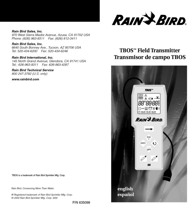
Rain Bird TBOS 635098 User manual
Rain Bird
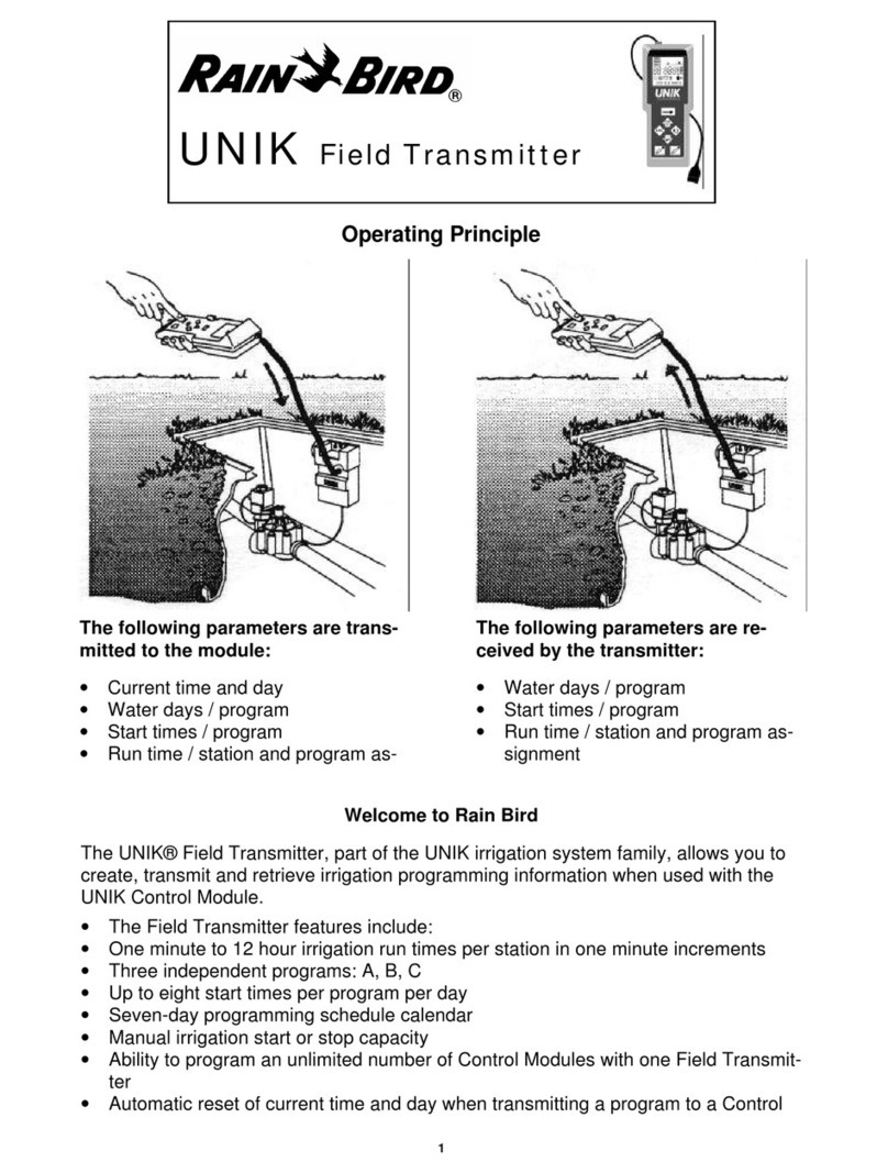
Rain Bird UNIK Field Transmitter Instruction sheet
Rain Bird
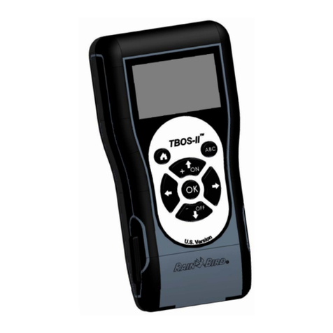
Rain Bird TBOS-II User manual

Rain Bird
Rain Bird TBOS-II User manual

Rain Bird
Rain Bird TBOS-II User manual
