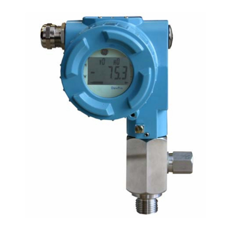
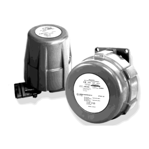
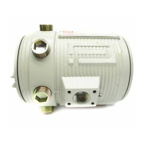
GE HygroPro User manual

GE
Measurement & Control Moisture
916-099 Rev. D
November 2012
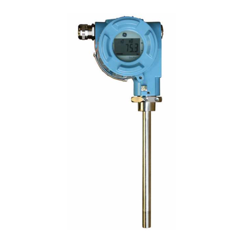
HygroPro
User’s Manual


www.ge-mcs.com
©2012 General Electric Company. All rights reserved.
Technical content subject to change without notice.
GE
Measurement & Control
HygroPro
Moisture Transmitter
User’s Manual
916-099 Rev. D
November 2012

ii
[no content intended for this page - proceed to next page]

HygroPro User’s Manual Page iii
Contents
Chapter 1: Installation
1.1 Introduction. . . . . . . . . . . . . . . . . . . . . . . . . . . . . . . . . . . . . . . . . .1
1.2 Sample System Guidelines . . . . . . . . . . . . . . . . . . . . . . . . . . . . . .2
1.3 Mounting the Transmitter . . . . . . . . . . . . . . . . . . . . . . . . . . . . . . .4
1.4 Wiring the Transmitter . . . . . . . . . . . . . . . . . . . . . . . . . . . . . . . . .5
1.4.1 Standard Wiring Connections . . . . . . . . . . . . . . . . . . . . . . .6
1.4.2 Hazardous Area Wiring Connections . . . . . . . . . . . . . . . .11
Chapter 2: Operation
2.1 Powering Up & Programming. . . . . . . . . . . . . . . . . . . . . . . . . . .19
2.1.1 Menu Map . . . . . . . . . . . . . . . . . . . . . . . . . . . . . . . . . . . . .20
2.1.2 Keypad. . . . . . . . . . . . . . . . . . . . . . . . . . . . . . . . . . . . . . . .21
2.2 Basic Setup . . . . . . . . . . . . . . . . . . . . . . . . . . . . . . . . . . . . . . . . .21
2.2.1 Unlocking the Display. . . . . . . . . . . . . . . . . . . . . . . . . . . .21
2.2.2 Entering the Setup Program. . . . . . . . . . . . . . . . . . . . . . . .22
2.2.3 Selecting Measurement Parameters. . . . . . . . . . . . . . . . . .23
2.2.4 Setting Up the Display. . . . . . . . . . . . . . . . . . . . . . . . . . . .25
2.2.5 Setting Up the Analog Output . . . . . . . . . . . . . . . . . . . . . .26
2.2.6 Entering the Node ID. . . . . . . . . . . . . . . . . . . . . . . . . . . . .28
2.2.7 Setting Up the RS485 Output . . . . . . . . . . . . . . . . . . . . . .29
2.3 Advanced Setup. . . . . . . . . . . . . . . . . . . . . . . . . . . . . . . . . . . . . .30
2.3.1 Setting Up the Pressure/Temperature Displays . . . . . . . . .30
2.3.2 Entering Sensor Calibration Data . . . . . . . . . . . . . . . . . . .31
2.3.3 Locking and Unlocking the Keypad . . . . . . . . . . . . . . . . .33
2.3.4 Locking and Unlocking the Menus . . . . . . . . . . . . . . . . . .33

Contents
Page iv HygroPro User’s Manual
Chapter 3: Service & Maintenance
3.1 The Service Menus . . . . . . . . . . . . . . . . . . . . . . . . . . . . . . . . . . 35
3.2 Moisture Probe Error Conditions. . . . . . . . . . . . . . . . . . . . . . . . 36
3.3 Cleaning the Moisture Probe. . . . . . . . . . . . . . . . . . . . . . . . . . . 36
3.3.1 Preparing to Clean the Probe . . . . . . . . . . . . . . . . . . . . . . 36
3.3.2 Replacing the RTE . . . . . . . . . . . . . . . . . . . . . . . . . . . . . . 37
3.3.3 Removing the Transmitter from the System . . . . . . . . . . 38
3.3.4 Removing the Probe from the Transmitter. . . . . . . . . . . . 38
3.3.5 Cleaning the Sensor and the Shield . . . . . . . . . . . . . . . . . 40
3.3.6 Installing the Probe in the Transmitter. . . . . . . . . . . . . . . 41
3.3.7 Evaluating the Cleaned Probe . . . . . . . . . . . . . . . . . . . . . 41
Chapter 4: Specifications
4.1 General. . . . . . . . . . . . . . . . . . . . . . . . . . . . . . . . . . . . . . . . . . . . 43
4.2 Electrical . . . . . . . . . . . . . . . . . . . . . . . . . . . . . . . . . . . . . . . . . . 44
4.3 Mechanical. . . . . . . . . . . . . . . . . . . . . . . . . . . . . . . . . . . . . . . . . 45
4.4 Moisture Sensor. . . . . . . . . . . . . . . . . . . . . . . . . . . . . . . . . . . . . 46
4.5 Built-In Temperature Sensor . . . . . . . . . . . . . . . . . . . . . . . . . . . 46
4.6 Built-In Pressure Sensor . . . . . . . . . . . . . . . . . . . . . . . . . . . . . . 47
4.7 Certifications . . . . . . . . . . . . . . . . . . . . . . . . . . . . . . . . . . . . . . . 48

HygroPro User’s Manual Page 1
Chapter 1: Installation
1.1 Introduction
The HygroPro Moisture Transmitter is a compact, intrinsically-safe,
loop-powered, 4-20 mA transmitter that provides accurate dew/frost
point measurements over a range of –110 to 20°C (-166 to 68°F). It
features an integrated display and a six-button keypad, and it is
housed in an IP67/Type 4X enclosure.
The HygroPro transmitter uses an aluminum oxide moisture sensor,
and it includes a temperature thermistor and a pressure transducer on
a common mount for calculation of parameters such as:
•ppmvin gases
•ppmwin liquids
•pounds per million standard cubic feet in natural gas
•process relative humidity.
IMPORTANT: To install the HygroPro in a hazardous (classified) area,
see Hazardous Area Wiring Connections on page 15.

Chapter 1: Installation
Page 2 HygroPro User’s Manual
1.2 Sample System Guidelines
The HygroPro transmitter can be installed in a sample system or
directly in the process line. However, GE recommends that the unit be
installed in a sample system to protect the probe from potentially
damaging components in the process stream. Figure 1 below shows a
typical sample system.
Figure 1: A Typical Sample System
Note: At least 5 ft (1.5 m) of 1/4” (6 mm) tubing vented to
atmosphere will ensure an accurate process sample and avoid
diffusion of ambient air moisture back into the process.
Flow
Probe
Valve 1
Valve 2 Flow Cell
See note below
Intake near the center of the
pipe is recommended.
HygroPro
Needle
Needle

HygroPro User’s Manual Page 3
Chapter 1: Installation
1.2 Sample System Guidelines (cont.)
In the sample system shown in Figure 1 on the previous page, fully
open Valve 1 and use Valve 2 to regulate the sample flow for
measurements at process system pressure. For measurements at
atmospheric pressure, fully open Valve 2 and use Valve 1 to regulate
the sample flow.
Before constructing a sample system, consult a GE application
engineer and observe the following guidelines:
•The sample system should be very simple and should contain as
few components as possible. All or most of those components
should be located downstream of the measurement point.
•Sample system components must not affect moisture readings.
Most common filters and pressure regulators are not suitable for
sample systems because the wetted parts adsorb moisture or
release moisture into the sample system. They may also allow
ambient contamination to enter the sample system. If possible, use
stainless steel for all wetted parts.
•The HygroPro probe should be oriented perpendicular to the
sample system inlet. For dimensions and other sample system
requirements see Mechanical Specifications on page 46.
•Sample systems should be tested for leaks prior to operation, using
a Snoop leak detector, to verify the integrity of connections,
components and fittings.
IMPORTANT: When pressurizing or depressurizing the sample system,
be careful to avoid shock damage to the moisture sensor.

Chapter 1: Installation
Page 4 HygroPro User’s Manual
1.3 Mounting the Transmitter
!CAUTION!
If the HygroPro will be installed directly into the process
line, consult GE for proper installation instructions and
precautions before proceeding.
Refer to Figure 2 below and complete the steps on the next page to
install the HygroPro transmitter.
Figure 2: HygroPro Installation
Probe Hex Nut
3/4-16 UNF-2A
Shield

HygroPro User’s Manual Page 5
Chapter 1: Installation
1.3 Mounting the Transmitter (cont.)
1. Make sure the sintered or stainless-steel shield is in place over the
sensor. This shield protects the aluminum oxide sensor from
damage during operation.
2. Using the integral 3/4-16 straight male thread, screw the probe end
of the transmitter into the process or sample system fitting. Make
sure not to damage the threads.
Note: A 3/4-16 to G 1/2 thread adapter is available from GE.
3. Using a 1-1/8” wrench on the probe hex nut, tighten the probe
securely into the process or sample system fitting.
!CAUTION!
Do not apply torque to the transmitter electronic module
to tighten the unit into its fitting.
Note: If there is insufficient space to rotate the HygroPro during
installation, remove the Replaceable Transducer Element (RTE)
from the transmitter, install it in the fitting, then re-install the
the transmitter onto the RTE.
1.4 Wiring the Transmitter
Proceed to the appropriate section for instructions on:
•Standard Wiring Connections (proceed to next page)
•Hazardous Area Wiring Connections (proceed page 15)

Chapter 1: Installation
Page 6 HygroPro User’s Manual
1.4.1 Standard Wiring Connections
The HygroPro is a 4-20 mA loop-powered device that can use the
same two wires for its measurement signal lines and its power supply
lines. Follow the instructions in this section only for units not
requiring hazardous (classified) area protection.
IMPORTANT: To install the HygroPro in a hazardous (classified) area,
see Hazardous Area Wiring Connections on page 15.
The transmitter must be wired using the factory-supplied, 2-meter
cable. If a different cable length is required, please contact the factory
for assistance.
Note: If a longer cable is required, you may splice an extension onto
the standard cable. Be sure to connect leads of the same color
together. For example, connect blue lead to blue lead, brown
lead to brown lead, etc.
The HygroPro may be connected to either of the following types of
external systems:
•an external device that can provide the loop power to the
HygroPro and can also receive and display the 4-20 mA
measurement output from the HygroPro (proceed to next page)
•an external power supply to provide power to the HygroPro plus a
personal computer (PC) running GE’s PanaView™ interface
software (proceed to page 13)

HygroPro User’s Manual Page 7
Chapter 1: Installation
1.4.1a Standard Connections - Without a PC
IMPORTANT: To install the HygroPro in a hazardous (classified) area,
see Hazardous Area Wiring Connections on page 15.
Refer to Figure 3 on the next page and Table 1 below, and complete
the following steps to wire the transmitter.
1. Push the female connector end of the factory-supplied cable into
the mating male connector on the transmitter module. Make sure
the pins are properly aligned. Then, secure the connectors together
by sliding the metal sleeve on the cable over the connectors and
turning it clockwise until it is tight.
2. Using the flying leads at the other end of the factory-supplied
cable, connect the transmitter to the external system.
Note: The blue and brown leads also carry the measurement signal
current output of 4-20 mA.
3. Trim any unused leads even with the outer cable jacket to remove
any bare wire and prevent accidental short circuits.
Table 1: Cable Leads - Without a PC
Lead Connection Description
Blue Power Supply (+) [12-28 VDC]
Brown Power Supply (–) [Return]
Shield Earth Ground [recommended]

Chapter 1: Installation
Page 8 HygroPro User’s Manual
1.4.1a Standard Connections - Without a PC (cont.)
Figure 3: Standard Connections - Without a PC
12-28 VDC
Return
Power and
Measurement
Circuits
+–
Shield
Earth
Ground
brownblue

HygroPro User’s Manual Page 9
Chapter 1: Installation
1.4.1b Standard Connections - With a PC
IMPORTANT: To install the HygroPro in a hazardous (classified) area,
see Hazardous Area Wiring Connections on page 15.
Refer to Figure 4 on the next page and Table 2 below, and complete
the following steps to wire the transmitter.
1. Connect an RS485-RS232 converter (customer-supplied) to an
available serial port on the PC.
2. Push the female connector end of the factory-supplied cable into
the mating male connector on the transmitter module. Make sure
the pins are properly aligned. Then, secure the connectors together
by sliding the metal sleeve on the cable over the connectors and
turning it clockwise until it is tight.
3. Using the flying leads at the other end of the factory-supplied
cable, connect the transmitter to the external system.
4. Trim any unused leads even with the outer cable jacket to remove
any bare wire and prevent accidental short circuits.
Table 2: Cable Leads - With a PC
Lead Connection Description
Blue Power Supply (+) [12-28 VDC]
Brown Power Supply (–) [Return]
White RS485-RS232 Converter (+) [positive]
Black RS485-RS232 Converter (–) [negative]
Ground Earth Ground

Chapter 1: Installation
Page 10 HygroPro User’s Manual
1.4.1b Standard Connections - With a PC (cont.)
Figure 4: Standard Connections - With a PC
+ White
Earth
Power
?Black
Ground
PanaView
RS232
RS485 ? RS232
Converter Box
24 VDC
Supply
Blue
Brown
+–

HygroPro User’s Manual Page 11
Chapter 1: Installation
1.4.2 Hazardous Area Wiring Connections
Before installing and using the HygroPro in a hazardous (classified)
area, be sure to read and understand all applicable reference materials.
This includes:
•all EU or North American Standards and Directives (see Table 3
and Table 4 on page 17)
•all local safety procedures and practices
•the FM Schematic drawing (see Figure 5 on the next page)
•this user’s manual
Note: It is the installer’s responsibility to follow all applicable
standards and procedures.
!WARNING!
The procedures in this section must be performed only
by trained technicians who have the necessary skills
and qualifications.

Chapter 1: Installation
Page 12 HygroPro User’s Manual
1.4.2 Hazardous Area Wiring Connections (cont.)
Figure 5: FM Schematic (ref. dwg #752-262)
Hazardous or Non-Hazardous Location
Class I, Division 1, Group ABCD
Class II, Division 1, Group EFG
Class III, Division 1 Non-Hazardous Location
HygroPro
Loop Terminal
Safety Entity Parameters:
Vmax = 28 V
Imax = 93.3 mA
Pi = 0.653 W
Ci = 0
Li = 62 uH
RS485 Comm Terminal
Safety Entity Parameters:
Vmax = 3.72 V
Imax = 228 mA
Pi = 212 mW
Ci = 0
Li = 62 uH
Notes:
1. Installation shall be in accordance with the National Electrical Code
(ANSI/NFPA 70) or Part One of the Canadian Electrical Code (C221),
as applicable.
2. The subject equipment is FM Approved, and FM Approved for Canada for the
following Hazardous (Classified) Locations and Protection Methods:
Intrinsically Safe, Class I, II, III, Division 1, Group ABCDEFG, T4
T Ambient: -40 C to 60 C
Enclosure: IP 67
3. Galvanically Isolated FM Approved (US) or Canadian Certified (for Canada)
associated apparatus installed in accordance with the manufactruer's instructions.
blue
brown
black
white
Associated Apparatus
Note 3 Loop-Power Device
Note 4
RS485 Comm
Note 4
Associated Apparatus
Note 3
4. Equipment to which associated apparatus is connected shall not
use or generate in excess of 250V.
5. Maintain the following relationship between Intrinsic Safety (Entity)
Parameters of HygroPro and associated apparatus:
HygroPro Vmax > associated apparatus Voc
HygroPro Imax > associated apparatus Isc
HygroPro Pi > associated apparatus Po
HygroPro Ci + Ccable < associated apparatus Ca
HygroPro Li + Lcable < associated apparatus La
Use cable P/N 230-049-01

HygroPro User’s Manual Page 13
Chapter 1: Installation
1.4.2a Applicable Standards and Directives
When the HygroPro is installed in hazardous areas with potentially
explosive atmospheres, it complies with the ATEX directive 94/9/EC,
the EU standards listed in Table 3 below, and the North American
FM/CSA and IEC standards listed in Table 4 below.
Table 3: European Union (EU) Standards
Title Number Date
General requirements EN 60079-0 2000
Intrinsic safety “i” EN 50020 2002
Group II, Category 1G, Zone 0 equipment EN 60079-26 2004
Table 4: North American Standards
Title Number Date
Electrical Equipment for Use in Hazardous
(Classified) Locations General
Requirements
Class No. 3600 Nov. 1998
Intrinsically Safe Apparatus and Associated
Apparatus for use in Class I, II, & III,
Division 1, and Class I, Zone 0 & 1
Hazardous (Classified) Locations
Class No. 3610 Oct. 1999
Electrical Equipment for Measurement,
Control and Laboratory Use Class No. 3810 Jan. 2005
Intrinsically Safe and Non-incendive
Electrical for Use in Hazardous Locations CSA-C22.2
No. 157 1992,
Reaffirmed
2002
Safety Requirements for Electrical
Equipment for Measurement, Control, and
Laboratory Use - Part 1: General
Requirements (Adopted IEC 61010-1:2001,
MOD) (Tri-National standard, with UL
61010-1 and ISA 82.02.01)
CSA-C22.2
No. 61010-1 July 2004
Degrees of Protection Provided by
Enclosures (IP Code) ANSI/IEC
60529 2004
Degrees of Protection Provided by
Enclosures (IP Code) CSA-C22.2
No. 60529 2005

Chapter 1: Installation
Page 14 HygroPro User’s Manual
1.4.2b Compliance Requirements
The HygroPro installation must comply with EN 60079-14 in Europe
and with the National Electrical Code (ANSI/NFPA 70) or part one of
the Canadian Electrical Code (C22.1), as applicable, in North
America. In other regions, additional local codes may also apply.
1.4.2c Electrical Connections
The HygroPro transmitter is certified intrinsically-safe for use in
zone 0. However, the external power must be provided by one of the
following methods:
•an isolated, intrinsically-safe, 24 VDC power supply mounted in
the safe area
•an isolated zener barrier mounted in the safe area and installed
between a standard 24 VDC power supply and the HygroPro
Refer to Figure 6 on the next page for a typical hazardous (classified)
area HygroPro wiring diagram. This installation uses an MTL706
zener barrier, in accordance with the second option listed above.
If using serial communications with a PC, an isolated RS232-RS485
converter mounted in the safe area between the computer and
HygroPro must be used. The converter is typically powered by its
own standard 24 VDC power supply.
!WARNING!
Do NOT power an RS232-RS485 converter from the
same intrinsically-safe 24 VDC power supply used
to power the HygroPro.
Table of contents
Other GE Transmitter manuals

GE
GE XMO2 User manual

GE
GE PanaFlow XMT1000 User manual

GE
GE DewPro MMY31 User manual

GE
GE VT6010 Installation instructions

GE
GE AquaTrans AT868 User manual

GE
GE Hart Druck RTX 1000H Series User manual

GE
GE IFS VT1101M Installation guide

GE
GE MASTR II User manual

GE
GE Masoneilan 12420 Installation and operating manual
GE
GE MDS TD220MAX User manual
Popular Transmitter manuals by other brands

Audiovox
Audiovox PurSuit 09XR1Pr Programming guide

HumanTechnik
HumanTechnik RadioLight operating instructions

CYP
CYP CHDBT-1H3CE Operation manual

RHEONIK
RHEONIK RHE26 Installation & start?up guide

BWI Eagle
BWI Eagle AIR-EAGLE XLT PLUS 497-5100-CHx-DC Product information bulletin

Nulaxy
Nulaxy KM28 user manual