Everyday Wireless TX-3B User manual
!!" #$%##$

i
Thank you for purchasing the Everyday Wireless Model TX-3B UHF FM Data Transceiver. Before
proceeding with the equipment installation, it is imperative that you read the following pages of notices and
precautions. In order to ensure your equipment installation complies with FCC specifications and fulfills all
warranty-related obligations, read comprehensively the IMPORTANT USER NOTICES and PRECAUTIONS
sections below.
IMPORTANT USER NOTICES
•FCC WARNING: This equipment generates or uses radio frequency energy. Changes or modifications
to this equipment may cause harmful interference unless the modifications are expressly approved in the
instruction manual. The user could lose the authority to operate this equipment if an unauthorized
change or modification is made.
•FCC RF Exposure Requirements: The antenna included with the Model TX-3bTransceiver must be
installed to provide a separation distance of at least 150 centimeters from all persons, must not be co-
located or operating in conjunction with any other antenna or transmitter, and must not exceed the
antenna gain specified in the Antenna Use description below. Failure to observe these restrictions will
result in exceeding the FCC RF exposure limits.
•Antenna Use: Various antennas are recommended, depending on customer requirements. A base station
antenna should be chosen based on licensing restrictions (ERP limitations). Suggested antennas,
depending on allowable ERP licensing, are as follows: Cushcraft CRX450B (7dBi, 450 – 470 MHz);
Antenex 4507 (9.14 dBi, 450 – 460 MHz); Antenex 4607 (9.14 dBi, 460 – 470 MHz); RFS 455-6 (12.14
dBi, 450 – 460 MHz); RFS 455-7 (12.14 dBi, 460 – 470 MHz). DO NOT use any other antenna with the
Model TX-3B Transceiver or modify the antenna / coaxial cabling without first consulting with
Everyday Wireless or an Everyday Wireless qualified service organization.
•Component Access: There are no service accessory parts inside the transceiver. Do not try to open the
transceiver without prior approval from Everyday Wireless. Opening the transceiver will void the
warranty.
•Service: Only qualified service personnel must install or repair equipment.
PRECAUTIONS
•Do not modify the transceiver for any reason.
•Do not expose the transceiver to long periods of direct sunlight, nor place it near heating appliances.
•The Model TX-3B UHF FM Transceiver transmits data in the 450-470 MHz frequency band, which is
regulated in the United States by the FCC. Because the FCC grants access to specific frequencies, and
can grant access by multiple users to the same frequency, system performance may be affected by the
presence of other nearby users of the frequency used by the owner of this transceiver.
•The United States Government is responsible for the operation, accuracy, and continued operation of the
Global Positioning System (GPS). Accuracy and position fixes (latitude, longitude and altitude) can be
affected by alterations made to the GPS satellites by the U. S. Government. Accuracy is subject to
change in accordance with the U. S. Department of Defense civil GPS user policy and Federal Radio-
navigation Plan. Positional accuracy and time to fix time can also be affected by poor view caused by

ii
obstructions such as tall buildings, heavy foliage, and large cliffs or other obstructions where GPS
satellite signals are blocked and poor satellite geometry conditions result.
DISCLAIMER AND LIMITATION OF LIABILITY
•Under no circumstances shall Everyday Wireless be responsible for any loss of data or any special,
incidental, consequential, or indirect damages howsoever caused. Everyday Wireless assumes no
responsibility for any damage or loss caused by deletion of data as a result of user error, malfunction, or
repairs.
•Everyday Wireless LLC assumes no responsibility for any damages or loss resulting from the use of this
product and user guide. Everyday Wireless LLC assumes no responsibility for any loss or claims by
third parties that may arise through the use of this system.
•The contents of this User Guide are provided “as is”, except as required by applicable laws, no
warranties of any kind, either express or implied, including but not limited to, the implied warranties of
merchantability and fitness for a particular purpose, are made in relation to the accuracy, reliability or
contents of this user guide. Everyday Wireless reserves the right to revise this user guide or withdraw it
at any time without prior notice. Everyday Wireless reserves the right to make changes and
improvements to any of the products described in this user guide.

iii
CONTENTS
Section 1 – Introduction ......................................................................................................................... 1
1.1) Product Description and Basic Operation................................................................................. 1
1.2) Technical Specifications........................................................................................................... 2
Section 2 – Receiving, Inspection, and Installation ............................................................................. 3
2.1) Packing Contents and Inspection.............................................................................................. 3
2.2) Installation ................................................................................................................................ 3
Section 3 – Maintenance......................................................................................................................... 6
3.1) Maintenance Concept ............................................................................................................... 6
3.2) Preventive Maintenance Requirements .................................................................................... 6
Section 4 – System Test .......................................................................................................................... 8

Section 1 - Introduction
1
Section 1 – Introduction
Note: Make sure you have read the IMPORTANT USER NOTICES and PRECAUTIONS sections
before proceeding with the installation instructions.
1.1) Product Description and Basic Operation
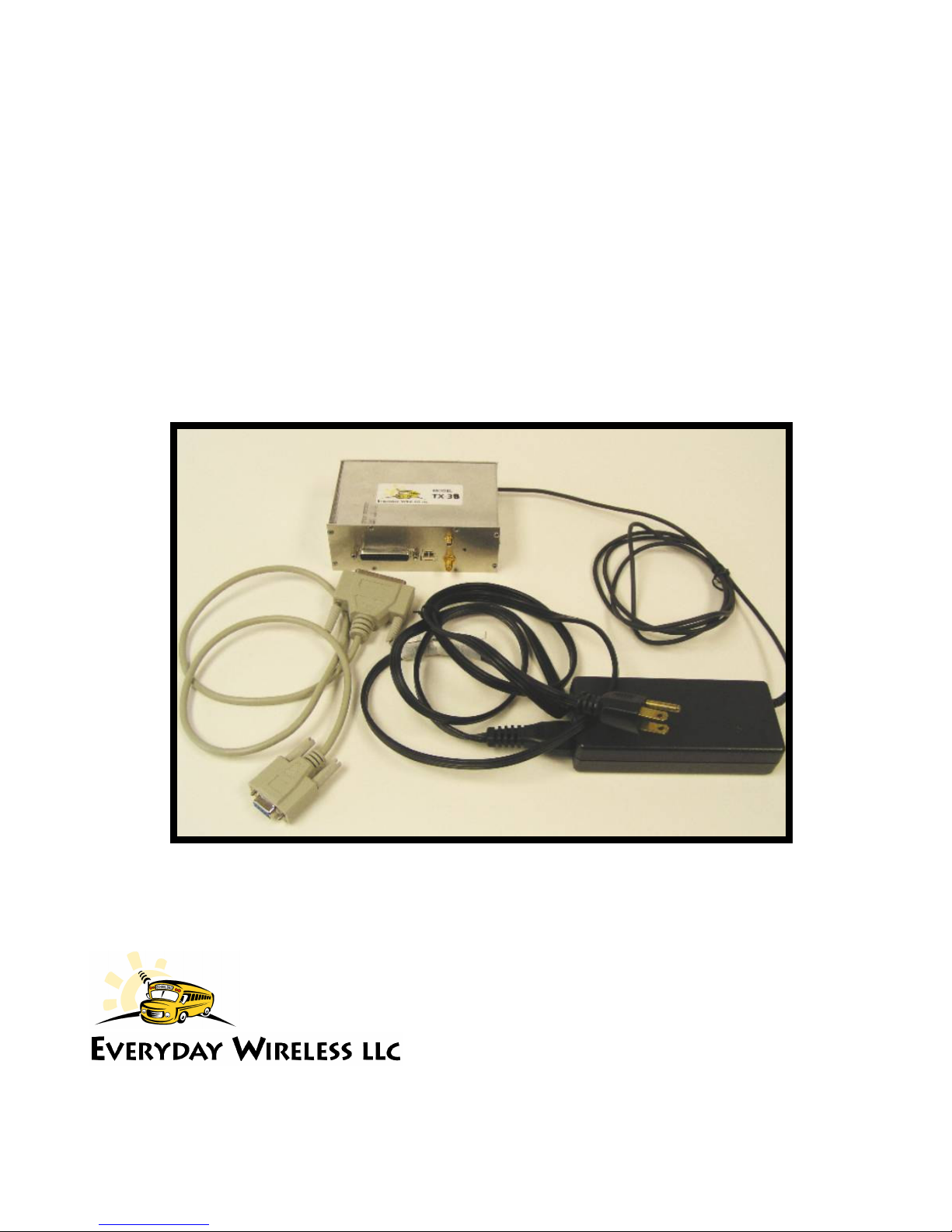
The Everyday Wireless Model TX-3B is a synthesized UHF FM data transceiver designed to operate in the
frequency range of 450 to 470 MHz. There are no user controls or adjustments.
The Everyday Wireless Model TX-3B is a half-duplex data communications device providing radio frequency
(RF) data transmit and receive functions. The Model TX-3B transceiver is an all-inclusive unit containing a
synthesized UHF data radio, GPS receiver, and supporting processing overhead to gather, compute, and transmit
information in real-time. The Model TX-3B design is intended to be used for 12.5 kHz channel data telemetry
applications.
Each Model TX-3B comes pre-programmed to a specific frequency licensed to each user. Reprogramming the
unit to a different frequency can only be accomplished by the manufacturer.
The Model TX-3B processes vehicle information transmitted from Everyday Wireless Model TX-3 and TX-3M
transceivers, and outputs this information serially through a DB25 connection. A DB25 to DB9 conversion cable
is provided that allows the TX-3B to be plugged into any standard serial interface. In addition, the TX-3B
transmits various commands to the Model TX-3 and TX-3M transceivers. Because data packets from the Model
TX-3B burst (typically 25 msec.) in a proprietary time slot protocol, message collisions are avoided and higher
throughputs are achieved.
The Model TX-3B has no user adjustments. Maximum output power is pre-set to 45 watts. The Model TX-3B
Transceiver unit should only be opened by the manufacturer.

Section 1 - Introduction
2
1.2) Technical Specifications
& $
!"#$%$ &'() * +,$-
$$.$ &/* +
!"#$. 0&
.#1 21 0
&3
.##$
4$ 5(& 6 21
% 5 6 21
.+ &78 9&79(&7
:&#$
$$;
<8 $8 $$
%! .) =/
> <. ) 9=/
4 #,$- '&0&&
4 #,- '0?
# 4$ ;53
$$$@ $ &
% A B2
$' ##
%!<8 C ## &8 :
) #$D $$ E!
%:4:.8 $4 5&
.##$* $C ## F(G
%
.$,G.@H - 5'G
@ %=$ F2G
@$ #$%=$ F2G
G/$ F(&G
=$ $$ F2G
@$ !"#$ &) * +$&&/* +
Section 2 – Receiving, Inspection,
3
and Installation
Section 2 – Receiving, Inspection, and Installation
Note: Make sure you have read the IMPORTANT USER NOTICES and PRECAUTIONS sections
before proceeding with the installation instructions.
2.1) Packing Contents and Inspection
Carefully unpack the transceiver and other installation items. Identify all of the items listed in the following
table before discarding the packing material. If any items have been damaged during shipment, file a claim with
the carrier immediately.
Supplied Accessories
#' (
#' )#*' + , *$##
A * !4$ ) 49'G
'#8 8 $I#,(& - < 49'G'
8 '%> '?%!,&J-8 H $$ %!'G'
H .) $$ %!C H 'H .)
& 8 '%> &?> <.,&J-8 ) 9$$ > <.'G'
2 $$ G* &H H
( > <.$$$ B2&'&
? ) #$$$8 ) .49'G'
B A $# A ) 49'G'
Antenna Options
)#- $#$$ ./# !0*$%
1 & $ $*
' 2/
%9&G #I %9&G J &'( (G ?
!> &( $$:!> &( B&J &'2 BG &
!> 2( $$:!> 2( B&J 2'( BG &
&&'2 %!.&&'2 ?&J &'2 G &
&&'( %!.&&'( ?&J 2'( G &
2.2) Installation
WARNING! VARIOUS ELECTRONIC EQUIPMENT IN YOUR FACILITY MAY MALFUNCTION IF THEY
ARE NOT PROPERLY PROTECTED FROM THE RADIO FREQUENCY ENERGY WHICH IS PRESENT
WHILE TRANSMITTING. CONSULT EVERYDAY WIRELESS OR AN EVERYDAY WIRELESS AUTHORIZED
REPRESENTATIVES IF ANY INTERFERENCE PROBLEMS OCCUR.
Note: The following preparation instructions are for use by your EVERYDAY WIRELESS dealer, an authorized
EVERYDAY WIRELESS service facility, or the factory.

Section 2 – Receiving, Inspection,
4
and Installation
Note: The antenna and transceiver require certain mounting surfaces and environments as described below. If
no suitable mounting surface is available, please contact EVERYDAY WIRELESS for alternative hardware and
mounting solutions.
Antenna and Transceiver Location
Choose a convenient, indoor location for the Model BS-3 Transceiver. This location must be accessible to wall
power, within 100’ of the computer that will receive messages, and 50’ from the rooftop antenna location.
Choose a remote location where the receiver will not be disturbed.
Antenna Installation
The rooftop antenna location should be at least 10 feet from nearby obstructions and at or near the highest point
of the roof. The antenna can be mounted with a non-penetrating antenna stand or on an antenna mast. Please
consult Everyday Wireless or an Everyday Wireless authorized representative to confirm that your desired
installation configuration is acceptable.
1. Mount the approved antenna to the antenna stand/mast. Make sure the antenna is secured reliably.
2. Connect the provided lightning arrestor to the base of the antenna, ensuring that the orientation of
the lightning arrestor is as described in the installation instructions provided with the lightning
arrestor.
3. Connect a suitable grounding wire, 6 or lower gauge copper wire (not provided by Everyday
Wireless), to the lightning arrestor and building ground. If no suitable building ground is available,
run a ground wire down to the ground and secure to a grounding rod.
4. The 50’ RG-8 coax antenna cable should now be connected to the base of the lightning arrestor and
run to the indoor location of the TX3-B Transceiver. Care should be taken to ensure that the
entrance point of the cable is adequately sealed as to prevent moisture to entering the facility. If the
50’ RG-8 coax cable is not long enough to reach from the rooftop antenna to the TX-3B Transceiver
location, consult Everyday Wireless before proceeding, as longer low loss cables are available for
an additional fee.
5. Run the RG-58 coaxial GPS cable in parallel with the RG-8 RF cable.
6. Feed the antenna leads to the location where the TX-3B Transceiver is located.
Caution: Care should be taken to ensure that there are no kinks in the coaxial cables and that the cable
will not be damaged by routing facility access and maintenance. Significant signal strength loss can
occur if the antenna cable is subjected to sharp corners and care should be taken to avoid such
circumstances.
TX-3B Installation
Note: Since there are no user adjustments necessary to operate the transceiver, mount the transceiver in
a convenient, yet enclosed and secured location.
1. Connect the RG-8 antenna cable to the TX-3B Transceiver using the provided N to SMA adapter.
2. Connect the RG-58 antenna cable to the TX-3B’s GPS antenna connector.
3. Secure the DB25 to DB9 adaptor cable to the TX3-B Transceiver.

Section 2 – Receiving, Inspection,
5
and Installation
4. Run the DB9 cable from the BS-3 Transceiver to the receiving computer and connect the cable to
both the computer and transceiver.
5. Connect the provided wall source power plug to the TX3-B, preferably through a UPS device.

Section 3 - Maintenance
6
Section 3 – Maintenance
In order to ensure that the TX3-B is always ready for operation, it should be checked periodically so that
potential problems may be discovered and corrected before they develop into any serious damage. A minimal
preventive maintenance program will significantly increase the transceiver’s lifespan.
This section describes the necessary preventive maintenance checks and tests the user can perform to easily
identify most defects and problems. Any other defects or problems discovered during the normal operation of
the system should be noted for future corrective measures.
CAUTION:
This section also describes the corrective maintenance checks that can be performed on the transceiver.
3.1) Maintenance Concept
The maintenance concept for the transceiver is limited to the removal and replacement of the entire unit.
3.2) Preventive Maintenance Requirements
The following is a recommended timetable for performing preventive maintenance checks on the transceiver.
CAUTION:
Inspection
The transceiver should be inspected at least every three (3) months for defects or physical damage developed
during operation. Inspect all the interface cables to and from the system for cracks, breaks, and proper seating
with their mating connectors on the faceplate. Inspect all cables for frayed, broken, or damaged wires. In
addition, inspect all transceiver connections for accumulation of dirt, grease, or any foreign material that can
cause a non-connection. If a cable is found damaged or non-repairable, it should be replaced before operating
the system again.
1. Confirm that the power cord plug is firmly locked into place at the transceiver unit.
2. Verify that the RF SMA connector is securely fastened.
a. Rotate the SMA connector clockwise to ensure the connection is tight.
3. Verify that the DB25 to DB9 adapter is firmly connected to the TX-3B transceiver’s DB25 port and
that the DB-9 cable is firmly connected to the adapter.
Inspection should be performed at least once every three (3) months. The frequency of inspection should be
increased for transceivers exposed to dusty or heavy particulate environments.
Stop the operation of the transceiver immediately if a problem is noted
during normal operation that can otherwise damage the system.
Primary power to the transceiver must be turned OFF when performing
preventive maintenance on the equipment.

Section 3 - Maintenance
7
Cleaning
Clean the outside surfaces and areas around the connectors once a year. Clean the surfaces with a clean, soft,
lint-free cloth. Clean the areas around the connectors with a soft bristle brush. To remove grease, fungus, or
corrosion, use a cloth dampened with an appropriate electronics cleaning fluid. Cleaning should be done at least
once every three months. The frequency of cleaning should be increased for units exposed to dusty or heavy
particulate environments.
Section 3 - Maintenance
8
Section 4 – System Test
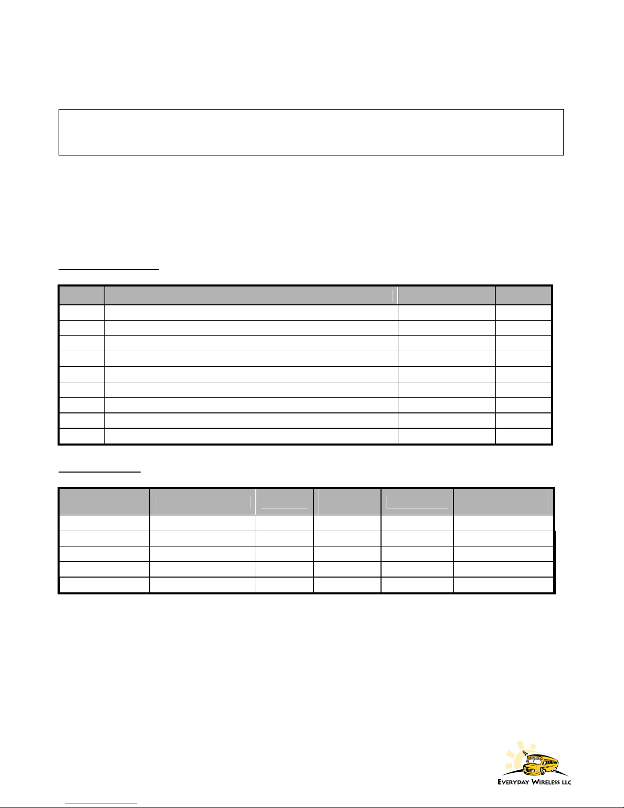
At the receiving computer, identify which COM port is receiving data from the DB-9 cable connected to the
base station receiver. Open the Hyper-Terminal program, which is generally found by clicking the Windows
Start Button – All Programs – Accessories – Communications. Name the connection “TX-3B Transceiver” and
then select any available icon. When the ‘Connect To’ dialog box appears, select the appropriate COM port
from the drop down list where it displays ‘Connect using’. Click ‘OK’ and the COM Properties dialog box will
appear which should be set to the settings shown below.
Once the settings are entered and ‘OK’ is clicked, you will be connected to the COM port. If Hyper-Terminal
does not allow you to connect to the correct COM port, another program may be using the port and it may be
necessary to access Windows Task Manager to ensure that you have completed exited any potential conflicting
software.

Section 3 - Maintenance
9
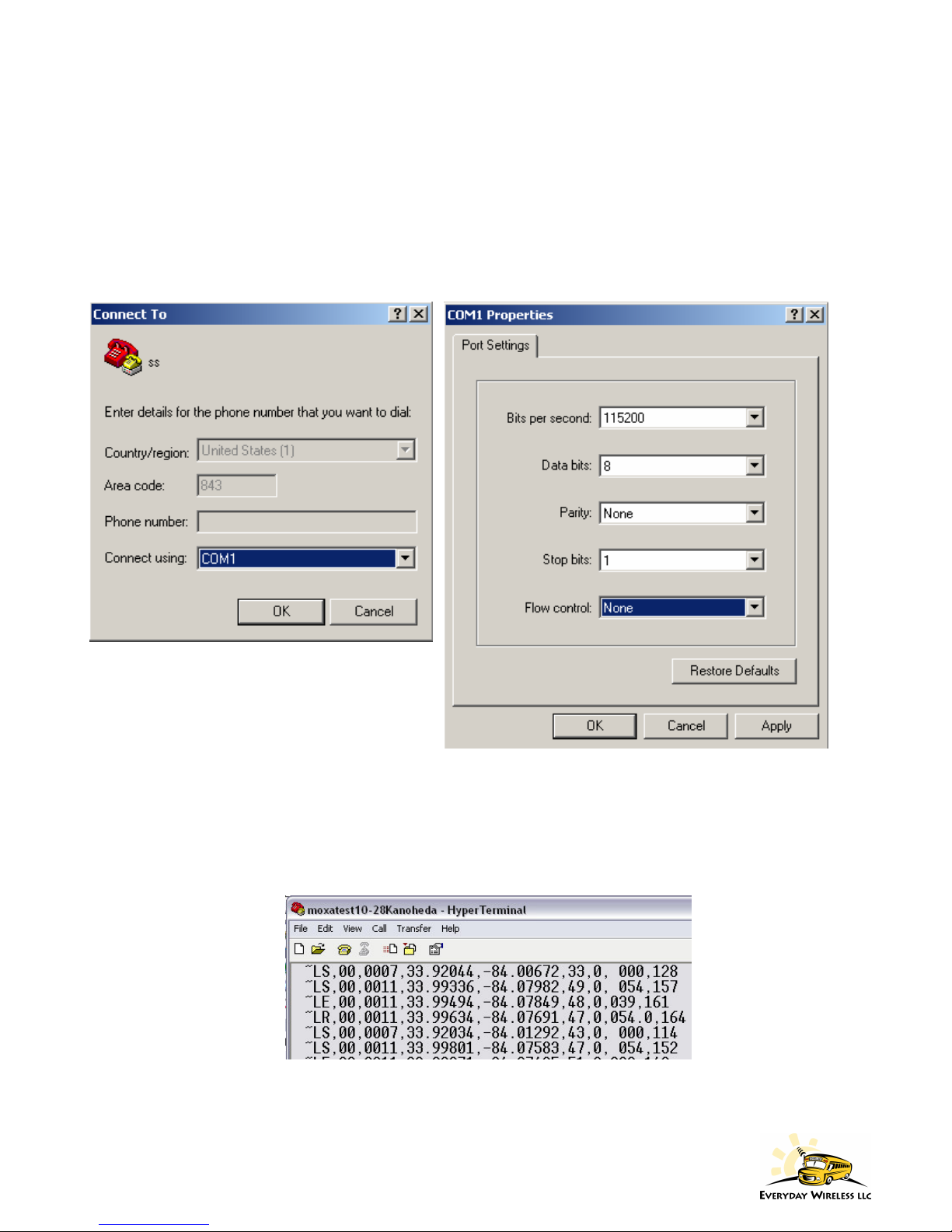
If buses are operating and within range of the base station antenna, data should begin to appear on the screen at
intervals of 10 seconds for each vehicle (similar to the data shown above). In addition, the base station should
be sending ‘heartbeat’ messages approximately once every 5 minutes. Data will appear as a series of comma
delimited values.
If no data is visible in Hyper-Terminal for a considerable length of time and buses are confirmed to be in
operation, it will be necessary to access the base station receiver. Check that the DB-9 cable is securely attached
to the computer and base station receiver, and that the receiver power supply is plugged into a UPS or wall jack
and that is it connected securely to the receiver. If all cabling and power supplies are connected properly and
data is still not visible in Hyper-Terminal, contact Everyday Wireless for further support.
Table of contents
Other Everyday Wireless Transceiver manuals


