Evi GT-SKR015KBDC-M10 User manual

EVI DC Inverter Air Source Heat Pump
Instruction Manual
Model number: GT-SKR015KBDC-M10
GT-SKR020KBDC-M10
GT-SKR030KBDC-M10
GT-SKR040KBDC-M10
GT-SKR050KBDC-M10
◆Please read the manual carefully before installation and maintenance.
◆Please keep this manual well for future reference.

CONTENTS
Part I: General Information......................................................................................................................... 1
1.1 Caution........................................................................................................................................... 1
Part II Installation ....................................................................................................................................... 2
2.1 Transportation................................................................................................................................ 2
2.2 Installation site requirement........................................................................................................... 2
2.3 Minimum distance to wall ............................................................................................................. 3
2.4 Clearance between outdoor module and ground............................................................................ 4
2.5 Installation guide............................................................................................................................ 4
2.6 Recommended hydraulic connection............................................................................................. 5
2.7 Electrical Connection..................................................................................................................... 6
2.8 Trial Operation............................................................................................................................... 7
Part III Control System............................................................................................................................... 8
3.1 Controller position......................................................................................................................... 8
3.2 Controller introduction................................................................................................................... 9
3.3 Operation introduction................................................................................................................... 9
Part IV Maintenance ................................................................................................................................. 28
Part V Trouble Shooting ........................................................................................................................... 29
Part VI Wiring Diagram............................................................................................................................ 35
Disposal.............................................................................................................................................. 38

- 1 -
Part I: General Information
1.1 Caution
1. Ensure proper operation on the unit,
2. The unit must be installed and repaired by qualified technician.
3. A leakage protection switch must be installed near the unit.
4. Do not use any damaged cables and switches to avoid any leakage.
5. Do not open the electrical box of the unit without shutting off power supply.
6. Along transportation, don’t incline the unit more than 45°in any direction.
7. Before maintenance, please shut off the power to the unit first.
8. The unit is designed for outdoor installation, do not install it in a close space without
good ventilation.
9. Do not install the unit near inflammable or explosive goods.
10. Do not block the air intake or outlet of the unit.
11. When the unit is in off status for more than 5 hours with the ambient temperature lower
than 2℃, please drain the unit to prevent the formulation of ice in it.
12. This unit is not intended for operation by persons (including children) with reduced
physical, sensory or mental capabilities, or lack of experience or knowledge, unless
they have been given supervision or instruction concerning use of the appliance by a
person responsible for their safety.
13. Keep safety distance between the unit and other equipment or structures according
local norm, and ensure that adequate space for maintenance or service operations.
14. Power supply: the diameter of electrical cables must be suitable for the unit and the
power supply voltage must correspond with the value indicated on the units. All units
must be earthed in conformity with legislation in force in the country concerned.
15. Please attention that hot water produced by the unit is not to be used for drink.
- 2 -
Part II Installation
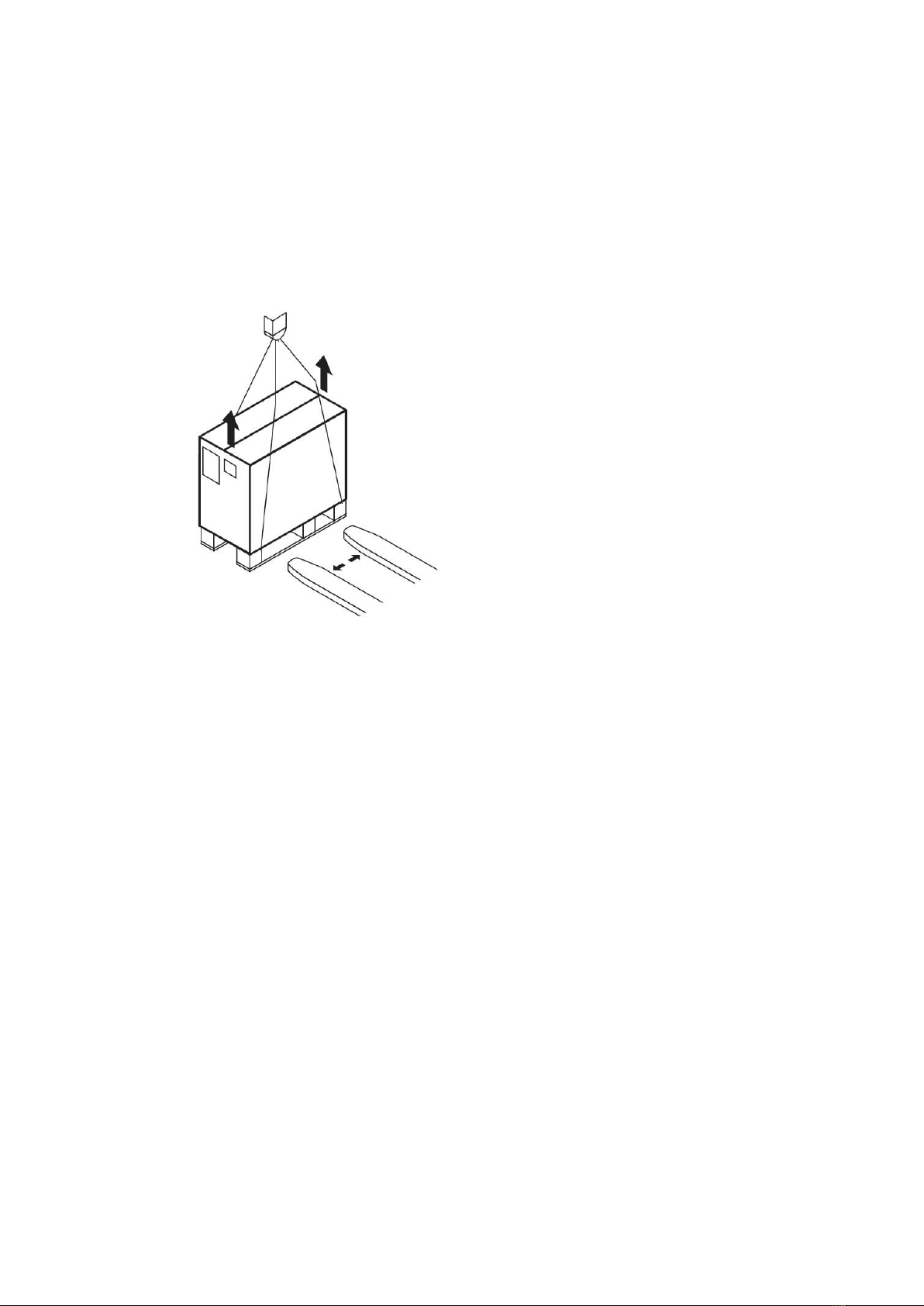
2.1 Transportation
Along transportation, don’t incline the unit more than 45°in any direction
The unit in its packaging can be transported with a lift truck or hand truck.
2.2 Installation site requirement
This unit is designed for outdoor installation, do not install it in an close space.
Please consider the condition as following factors when selecting installation site.
●The installation site should be large enough and well ventilation.
●The installation site should be convenient for water drainage.
●Select a smooth, horizontal site where it can support the weight of the unit.
●Do not install the unit where there is pollution, accumulation, fallen leaves or bad ventilation.
●Don’t install the unit near inflammable or explosive goods.

- 3 -
2.3 Minimum distance to wall
Air discharge
Minimum 1000mm to obstacles obstructing the air discharge.
Minimum 3000mm to footpaths and patios due to the formation of ice, even when outside
temperatures are above 0 °C

- 4 -
2.4 Clearance between outdoor module and ground
The minimum installation height must be 300mm.
A canopy must be constructed over the outdoor module in areas with heavy snowfall.
2.5 Installation guide
2.5.1 Installation
a. Install 4 pieces shockproof rubber pad under the feet of the unit.
b. If the unit work with a water tank, the vertical distance between the unit and the water
tank should be less than 6m, and the horizontal distance should be less than 20m.
c. Connect the condensate drainage connector to the hole at the bottom sheet.
2.5.2 Accessories
Accessories inside the package as below table
No
Item
Quantity
1
Instruction Manual
1
2
Condensate drainage connector
2
3
shockproof rubber pads
4

- 5 -
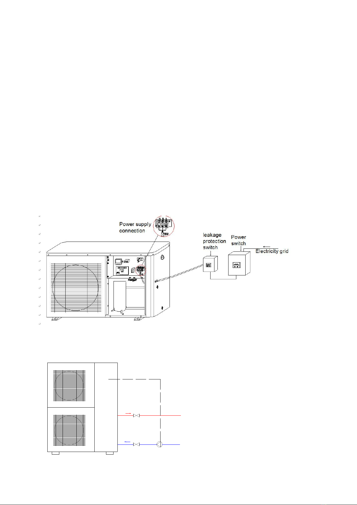
2.6 Recommended hydraulic connection
- 6 -
2.7 Electrical Connection
1. Ensure proper operation of the unit, the unit must be installed and repaired by qualified
technician.
2. A leakage protection switch must be installed near the unit.
3. Do not use any damaged cable and switch.
4. Do not open the electrical box without shutting off all power to the unit.
All the wiring must meet the local electrical safety norm and performed by qualified
electricians.
Ensure that the heat pump water heater is well connected to the earth, do not disconnect
the earth connection of the power in any condition.
Provide a separate power supply which meets rated requirements for the unit.
When the unit connects to the electricity network, there must be a short-circuit protection.
Choose the suitable cable when use the power outdoor.
Do not control the unit on or off by the main power switch.
After finish installation, check before connect the unit to the power.
Connect the signal (power) from PCB to water circulation pump
Heat pump Water circulation pump
Water circulation pump
signal (power)

- 7 -
The Specification of Power
Following information is for reference, please subject to the local safety norm.
Type
GT-SKR015KB
DC-M10
GT-SKR020KB
DC-M10
GT-SKR030KB
DC-M10
GT-SKR040KB
DC-M10
GT-SKR050KB
DC-M10
Power supply
220-240V/1Ph/
50Hz
220-240V/1Ph/
50Hz
220-240V/1Ph/
50Hz
220-240V/1Ph/
50Hz
380-415V/3Ph/
50Hz
Circuit
Breaker/Fuse(A)
20
25
32
32
32
Min. power
wiring (mm2)
1.5
2.5
4.0
4.0
2.5
Ground wiring
(mm2)
1.5
2.5
2.5
2.5
2.5
2.8 Trial Operation
The unit should only be operated by qualified technician.
Please drain air inside hydraulic system before operation.
The unit is designed according to the conditions as follows: the range of ambient
temperature is -25℃~43℃and the range of water pressure is 0.15~0.8Mpa.
2.8.1 Preparation
The following items should be checked before startup:
a. The heat pump should be connected completely.
b. All valves that could impair the proper flow of the heating water in the heating circuit must be
open.
c. The air intake and air outlet paths must be cleared.
d. The ventilator must turn in the direction indicated by the arrow.
e. The settings of the heat pump controller must be adapted to the heating system in
accordance with the controller’s operating instructions.
f. Ensure the condensate outflow functions.
g. Drain the air inside hydraulic system.
2.8.2 Trial run
●Turn on the power, start up the unit by the controller, after 30 seconds, the unit (compressor)
start to work, then observe whether the unit works normally.
●When you restart the unit, the compressor will start up after three minutes to protect the
compressor.

- 8 -
2.8.3 Caution
When following happen during trial operation, please stop the unit immediately and cut off the
power and contact with our authorized agent or maintenance technician.
Fuse blown or protection activated frequently.
●The wire and switches are heated abnormally
●Abnormal sounds coming from the unit
●Abnormal smell comes out of the unit.
●Electricity leakage.
Part III Control System
3.1 Controller position
The controller is installed inside the unit before factory, open the front panel as following picture,
you will find the controller.
There is 8 meters cable for the controller, it is allowable to move the controller to outside the unit,
but avoid a place with sunshine and rain.
- 9 -
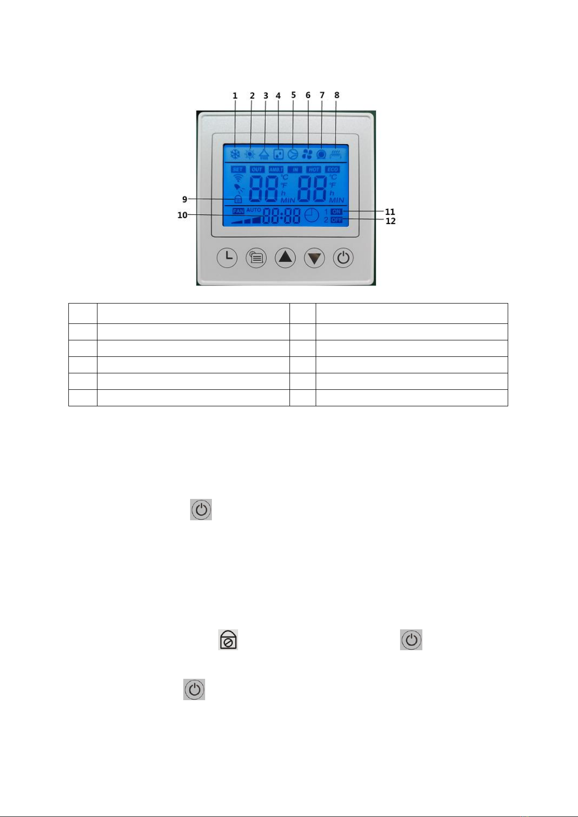
3.2 Controller introduction
1
Cooling
7
Water pump
2
Heating
8
E-heater
3
DHW
9
Lock the keys
4
Defrosting
10
Clock
5
Compressor
11
Timer on
6
Fan
12
Timer off
3.3 Operation introduction
Lock and unlock buttons
1. In locked status, press button for 5 seconds, the buzzer will sound and unlock the
buttons.
2. If there is no operation for 60 seconds, buttons will be locked automatically, and the
backlight will be off.
Turn on/Off the unit
1. When the buttons are locked, displace on the screen, press button for 5 seconds
to unlock the screen;
2. In unlock status, press button for 1 second to switch on/off;
3. In unlock status, if there is no operation on the controller for 60 seconds, the buttons will be
locked automatically.

- 10 -
Standby status
Function button
1. In main menu, press button to switch working mode.
The units have 5 working modes as below:
(1): Heating mode
The left side of the screen shows the set water temperature of buffer tank; The right side of
the screen shows the measured water temperature of buffer tank. Press or to
adjust the set water temperature of buffer tank, the maximum water temperature can be
set is 60℃.
Heating status
(2): cooling mode
The left side of the screen shows the set water temperature of buffer tank; The right side of
the screen shows the measured water temperature of buffer tank. Press or to
adjust the set water temperature of buffer tank, the minimum water temperature can be set
is 8℃.
Cooling status
- 11 -
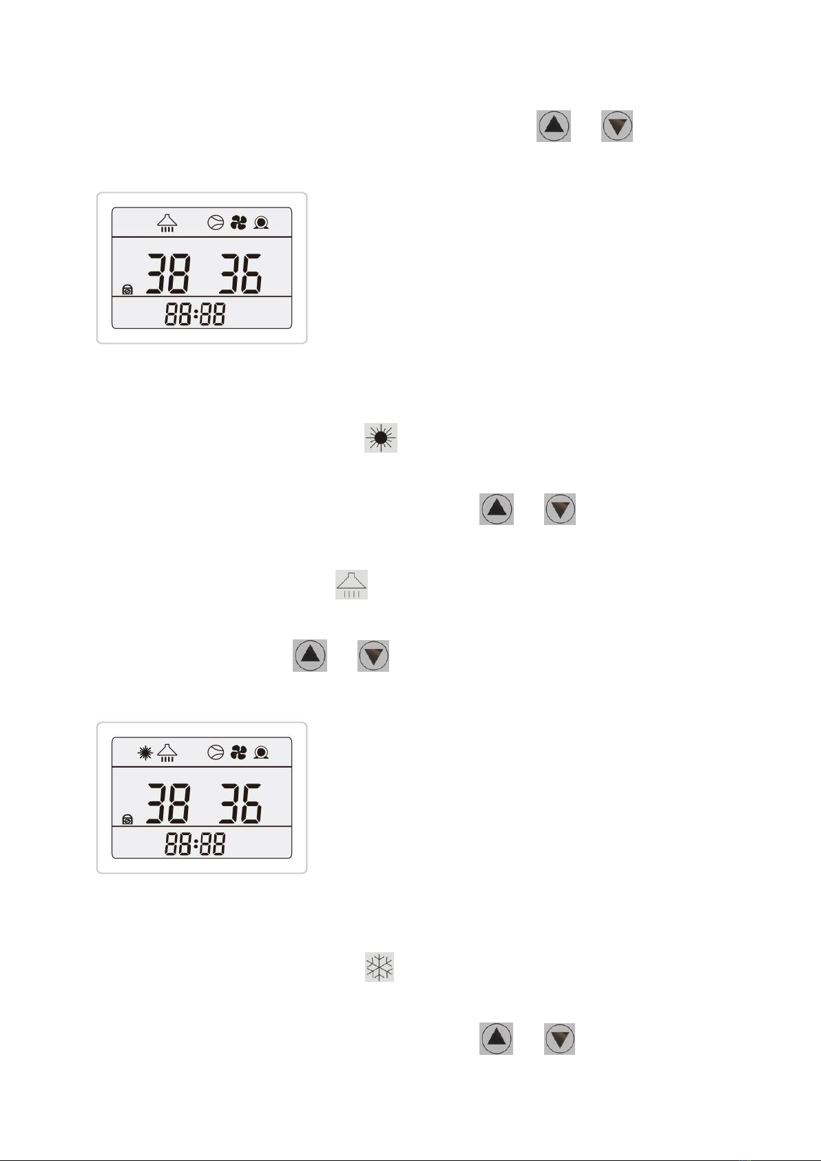
(3): DHW mode
The left side of the screen shows the set DHW water temperature; The right side of the
screen shows the measured DHW water temperature. Press or to adjust the set
DHW water temperature, the maximum DHW water temperature can be set is 55℃.
DHW status
(4): heating + DHW mode (DHW priority)
-When the unit is in heating status, flash on the screen, the left side of the screen
shows the set water temperature of buffer tank; The right side of the screen shows the
measured water temperature of buffer tank. Press or to adjust the set water
temperature of buffer tank, the maximum water temperature can be set is 60℃.
-When the unit is in DHW status, flash on the screen, the left side of the screen shows
the set DHW water temperature; The right side of the screen shows the measured DHW
water temperature. Press or to adjust the set DHW water temperature, the
maximum DHW water temperature can be set is 55℃.
Heating+ DHW status
(5): cooling + DHW (DHW priority)
-When the unit is in cooling status, flash on the screen, the left side of the screen
shows the set water temperature of buffer tank; The right side of the screen shows the
measured water temperature of buffer tank. Press or to adjust the set water

- 12 -
temperature of buffer tank, the minimum water temperature can be set is 8℃.
-When the unit is in DHW status, flash on the screen, the left side of the screen shows
the set DHW water temperature; The right side of the screen shows the measured DHW
water temperature. Press or to adjust the set DHW water temperature, the
maximum DHW water temperature can be set is 55℃.
Cooling+ DHW status
Parameter inquiry
1. In main menu, press button for 3 seconds to enter user parameter inquiry menu,
press or button to inquire parameters.
2. In user parameter inquiry menu, if there is no operation for 30 seconds, will automatically
exit user parameter inquiry and back to main menu. Or press button to back to main
menu.
Item
Description
Unit
Range
Remark
00
DHW tank temperature
℃
-30~105
01
Frequency of compressor
Hz
0~99
02
Current of compressor
A
-30~105
03
DC bus voltage
V
-30~105
*10
04
Temperature of IPM module
℃
-30~105
05
AC voltage
V
-30~105
*10
06
AC current
A
-30~105
07
Current operating power of compressor
W
-30~105
*100
08
Fan speed
RPM
-30~105
*10
09
Target overheating of suction in main circuit
℃
-30~105
/10
10
Actual overheating of suction in main circuit
℃
-30~105
- 13 -
11
EEV opening in main circuit
P
-30~105
*10
12
EEV opening in injection circuit
P
*10
13
High pressure
Kpa
-30~105
*100
14
High pressure saturated evaporation
temperature
℃
-30~105
15
Current exhaust superheat
℃
-30~105
16
Low pressure in main circuit
Kpa
-30~105
*100
17
Low pressure saturated evaporation
temperature
℃
-30~105
18
Target overheating in auxiliary circuit
℃
-30~105
19
Actual overheating in auxiliary circuit
℃
-30~105
20
Low pressure in auxiliary circuit
KPa
-30~105
*100
21
Inlet temp of auxiliary circuit
℃
-30~105
Low pressure saturated
evaporation temperature in
auxiliary circuit
22
Outlet temp of auxiliary circuit
℃
-30~105
EVI suction temperature
23
Exhaust temp
℃
-30~140
24
Outdoor coil temperature
℃
-30~105
25
Outdoor environment temperature
℃
-30~105
26
Buffer tank temperature
℃
-30~105
27
Temperature of after throttling
℃
-30~105
28
Inlet water temperature
℃
-30~105
29
Outlet water temperature
℃
-30~105
30
Suction temperature
℃
-30~105
31
Casecade switch selection
0: OFF; 1: ON
32
Casecade switch status
0: OFF; 1: ON
33
Status of water pump
0:OFF; 1: ON
Factory parameters setting ( only for technician operate)
1. In main menu, press button for 3 seconds to enter parameter setting menu, press
or button to set parameters. Press button to save setting.

- 14 -
2. In parameter setting menu, if there is no operation for 30 seconds, will automatically exit
parameter setting and back to main menu. Or press button to back to main menu.
Item
Description
Default
value
Unit
Range
Remark
b01
Water difference to start
compressor in heating mode
3
℃
0~15
b02
Water difference to start
compressor in cooling mode
3
℃
0~15
b03
Max. set temperature in heating
mode
60
℃
20~60
b04
Min. set temperature in heating
mode
15
℃
10~20
b05
Max. set temperature in cooling
mode
32
℃
20~60
b06
Min. set temperature in cooling
mode
8
℃
7~20
b07
Water temperature compensation
0
℃
-9~9
b08
Circulation running mode
2
0~2
0: run 2 mins every b09 mins
1: run as compressor run
2: always run
b09
Circulation pump interval time
5
min
0~99
b10
Inlet and outlet water temperature
difference protection value
40
℃
5~40
b11
Working mode
3
0~1
0: heating
1:heating+DHW
2: heating+cooling
3: heating+cooling+DHW
After setting, it needs to be
powered off to take effect.
b12
Power lost memory function
1
0~1
0: off
1: on
b13
Air temperature to start E-heater
-15
-30~20
b14
Air temperature to enter EVI
8
0~10
b15
Type of fan
0
0~3
0: DC
1: single speed
2: double speed
3: three speed
After setting, it needs to be
powered off to take effect.

- 15 -
b16
Water temperature compensation
function
1
0~1
0: no
1: yes
b17
Set room temperature
25
℃
15~25
b18
Initial BTW temperature
20
℃
15~25
b19
Max. BTW temperature
43
℃
24~50
b20
Extend defrosting interval 1
0
min
-30~50
b21
Extend defrosting interval 2
0
min
-30~50
b22
Defrosting enter temp 1
0
℃
-30~30
b23
Defrosting enter temp 2
0
℃
-30~30
b24
Defrosting running time
12
min
6~16
b25
Defrosting exit temperature 1
EE
℃
12~25
b26
Defrosting exit temperature 2
5
℃
4~11
b27
Reserved
0
b28
Reserved
0
b29
Reserved
0
b30
Main valve target exhaust
superheat in heating
EE
℃
0~10
b31
Main valve target exhaust
superheat in cooling
EE
℃
0~10
b32
Main valve regulating interval time
EE
s
30~90
b33
Min. opening of main valve in
cooling
EE
P
50~480
b34
Min. opening of main valve in
heating
EE
P
50~480
b35
Main valve target return superheat
max. value in heating
EE
℃
0~10
b36
Main valve target return superheat
max. value in cooling
EE
℃
0~10
b37
Reserved
0
b38
Auxiliary valve target superheat
EE
℃
0~15
b39
Auxiliary valve regulating interval
time
EE
s
30~90
b40
Reserved
b41
Reserved
b42
Reserved
b43
Reserved
b44
Reserved

- 16 -
b45
Max. operating temperature in
heating
55
℃
10~60
b46
Min. operating temperature in
heating
-25
℃
-35~10
b47
Reserved
0
b48
Reserved
0
1~13
b49
Reserved
0
1~13
b50
Reserved
0
1~10
b51
Reserved
0
1~10
b52
Reserved
0
0~1
b53
Reserved
0
℃
0~5
b54
Reserved
0
b55
Quantity of machines work in
series
1
1~8
b56
Display machine work in series
1
1~8
b57
Reserved
0
b58
Reserved
0
b59
Reserved
0
cure
b60
Manual debugging mode
0
0~1
0: off
1: on
b61
Manual compressor running
frequency
60
HZ
0~95
Default value is current running
frequency
b62
Manual main valve opening
300
HZ
0~480
Default value is current running
frequency
b63
Manual auxiliary valve opening
100
P
0~480
Default value is current running
frequency
b64
DC fan speed
850
P
400~10
00
Default value is current running
frequency
b65
Reserved
b66
Reserved
b67
Reserved
b68
Reserved
b69
Reserved
b70
Reserved

- 17 -
Defrosting parameters setting (only for technician operating)
1. In main menu, press button for 3 seconds to enter parameter setting menu, press
or button to set parameters. Press button to save setting.
2. In parameter setting menu, if there is no operation for 30 seconds, will automatically exit
parameter setting and back to main menu. Or press button to back to main menu.
Item
Description
Default
value
Unit
Range
Remark
b20
Extend defrosting interval 1
0
min
-30~50
value=x, interval time of
defrosting=(60+x) mins.
b21
Extend defrosting interval 2
0
min
-30~50
value=x, interval time of
defrosting=(60+x) mins.
b22
Defrosting enter temp 1
0
℃
-30~30
this value is temp difference
(environment temp-coil temp)
b23
Defrosting enter temp 2
0
℃
-30~30
this value is temp difference
(environment temp-coil temp)
b24
Defrosting running time
12
min
6~16
b25
Defrosting exit temp 1
15
℃
12~25
b26
Defrosting exit temp 2
5
℃
4~11
ECO mode
In ECO mode, the unit runs according to heating curve.
The heating curve is the relationship between the heating system supply temperature and the
outside air temperature. In the case of a heating curve, it is done automatically thanks to the
weather-based control, which adjusts the supply temperature based on the outside
temperature.

- 18 -
1. Press , and buttons simultaneously to enter / exit ECO mode,
display on the screen.
The heating curve parameters setting (only for technician operation)
a. In main menu, press button for 3 seconds to enter parameter setting menu, press
or button to set parameters. Press button to save setting.
b. In parameter setting menu, if there is no operation for 30 seconds, will automatically exit
parameter setting and back to main menu. Or press button to back to main menu.
Item
Description
Default value
Unit
Range
b17
Set room temp
25
℃
15~25℃
b18
Initial BTW temp
20
℃
15~25℃
b19
Max. BTW temp
43
℃
24~50℃
Target buffer tank temp = Initial BTW temp + (Max BTM temp - Initial BTW temp) / 35 x (Set
room temp - Outside temp)
For example, Set room temp = 25°C, Max BTW temp = 43°C, Initial BTW temp = 20°C
a. When outside temp=20°C, Target buffer tank temp = 20+(43-20)/35x(25-20)=23°C
This manual suits for next models
4
Table of contents
Other Evi Heat Pump manuals

Popular Heat Pump manuals by other brands


Hitachi
Hitachi YUTAKI S Series Installation and operation manual

Bosch
Bosch Compress 7000 AWM/AWMS 5-17 user guide

Boge
Boge BEKOMAT 32 Instructions for operation

Apricus
Apricus APHP-R290-260 installation manual

Carrier
Carrier Aquasnap plus 30AW Installation, operation and maintenance instructions

Haier
Haier MRVII-S AU482FIERA Installation & maintenance instructions


