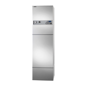
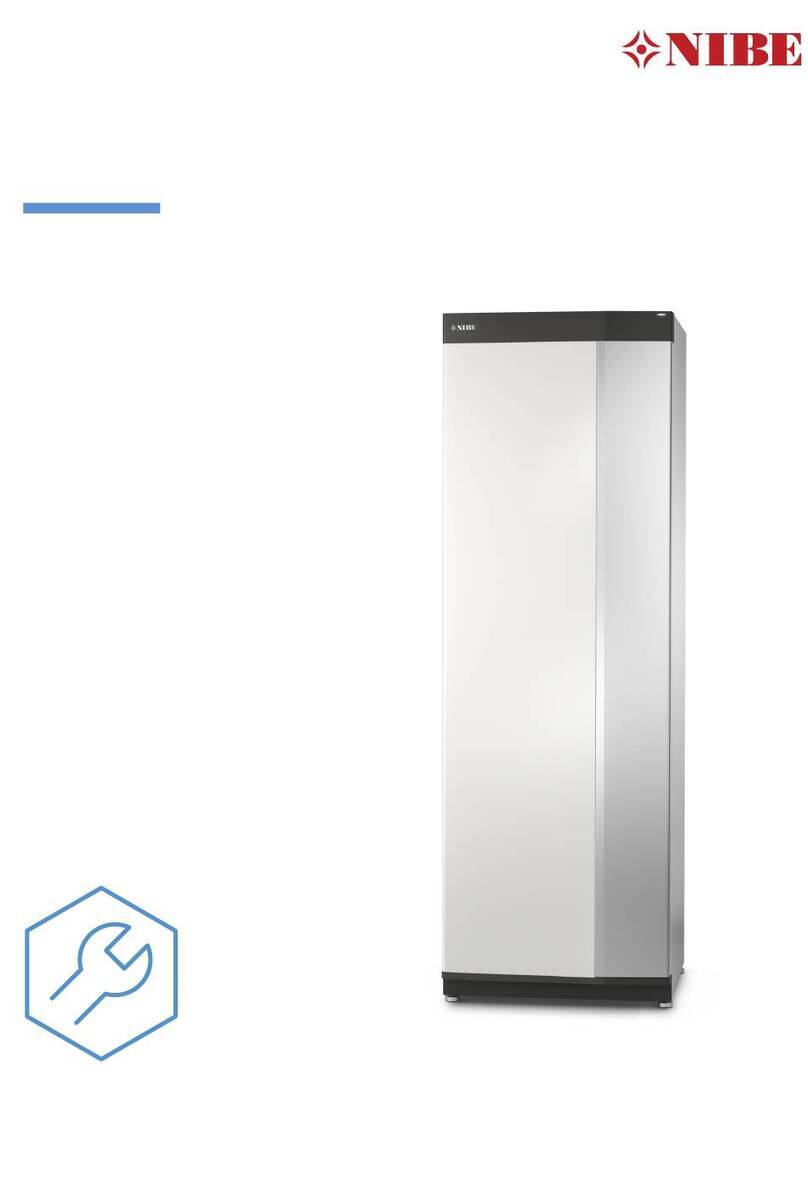
Nibe F110 User manual

IHB EN 1927-6
231974
INSTALLATION MANUAL
Hot water heat pump
NIBE F110
LEK

Quick guide
Navigation Ok button (confirm/select)
Back button (back/undo/exit)
Up/down buttons
(move/increase/reduce)
A detailed explanation of the button functions can be found on page 22.
How to scroll through menus and make different settings is described on page 24.
Increase hot water volume
true
off
2X
1X
To temporarily increase the amount of hot water, first press the down button to mark menu 2 (water droplet)
and then press the OK button twice. Read more about the settings on page 26.
In event of disturbances in comfort
If a disturbance in comfort of any type occurs there are some measures that can be taken before you need to
contact your installer. See page 34 for instructions.

41 Important information
4Safety information
4Symbols
4Marking
5Serial number
5Recovery
6Inspection of the installation
72 Delivery and handling
7Transport
7Assembly
8Supplied components
8Removing the covers
103 The Heat pump design
10Component positions
11List of components
124 Pipe and air connections
12General pipe connections
13Dimensions and pipe connections
14Installation alternative
16General ventilation connections
17Dimension and ventilation connections
17Ventilation flow (exhaust air)
17Adjusting ventilation (exhaust air)
185 Electrical connections
18General
18Connections
19Optional connections
206 Commissioning and adjusting
20Preparations
20Filling and venting
20Start-up and inspection
227 Control - Introduction
22Display unit
22Menu system
258 Control - Menus
25Menu 1 - ventilation
26Menu 2 - HOT WATER
28Menu 3 - INFO
29Menu 4 - MY SYSTEM
30Menu 5 - SERVICE
339 Service
33Service actions
3410 Disturbances in comfort
34Info menu
34Manage alarm
3611 Accessories
36Separable valve connector
36Base extension EF 45
36Top cabinet
3712 Technical data
37Dimensions and setting-out coordinates
38Technical specifications
39Energy labelling
40Electrical circuit diagram
41Item register
43Contact information
3Table of ContentsNIBE F110
Table of Contents

Safety information
This manual describes installation and service proced-
ures for implementation by specialists.
The manual must be left with the customer.
This appliance can be used by children
aged from 8 years and above and persons
with reduced physical, sensory or mental
capabilities or lack of experience and
knowledge if they have been given super-
vision or instruction concerning use of the
appliance in a safe way and understand
the hazards involved. Children shall not
play with the appliance. Cleaning and user
maintenance shall not be made by children
without supervision.
Rights to make any design or technical
modifications are reserved.
©NIBE 2019.
Water may drip from the safety valve’s
overflow pipe. The entire length of the over-
flow water pipe must be routed to a suitable
drain and be inclined to prevent water pock-
ets, and must also be frost-proof. The over-
flow pipe must be at least the same size as
the safety valve. The overflow pipe must be
visible and its mouth must be open and not
located close to electrical components.
Symbols
NOTE
This symbol indicates danger to person or ma-
chine .
Caution
This symbol indicates important information
about what you should consider when installing
or servicing the installation.
TIP
This symbol indicates tips on how to facilitate
using the product.
Marking
The CE mark is obligatory for most products sold
in the EU, regardless of where they are made.
CE
Classification of enclosure of electro-technical
equipment.
IP21
Read the User Manual.
Read the Installer Manual.
NIBE F110Chapter 1 | Important information4
1 Important information

Serial number
The serial number can be found at the bottom right of
the front cover.
Serial number
Caution
You need the product's (14 digit) serial number
for servicing and support.
Recovery
Leave the disposal of the packaging to the in-
staller who installed the product or to special
waste stations.
Do not dispose of used products with normal
household waste. It must be disposed of at a
special waste station or dealer who provides this type
of service.
Improper disposal of the product by the user results in
administrative penalties in accordance with current le-
gislation.
5Chapter 1 | Important informationNIBE F110

Inspection of the installation
Current regulations require the heating installation to be inspected before it is commissioned. The inspection must
be carried out by a suitably qualified person.
DateSigna-
ture
NotesDescription
✔
Ventilation, exhaust air (page 14)
Setting the ventilation flow
Exhaust air filter
Ventilation, surrounding air or outdoor air
(page 15)
Pressure drop in the system
Hot water
System vented
Electricity (page 18)
Supply connected 230 V
Circuit fuses
Earth circuit-breaker
Miscellaneous
Type of installation
NIBE F110Chapter 1 | Important information6

Transport
F110 should be transported and stored vertically in a dry
place. However. the F110 may be carefully laid on its
back when being moved into a building. The centre of
gravity is in the upper part.
R
0
R
0
Assembly
• Position F110 on a solid foundation indoors that with-
stands water and the weight of the heat pump. Use
the product’s adjustable feet to obtain a horizontal and
stable set-up.
30 - 50 mm
30 - 50 mm
15 - 40 mm
20-55 mm
• Because water comes from F110, the area where the
heating pump is located must be equipped with floor
drainage.
•Install with its back to an outside wall, ideally in a room
where noise does not matter, in order to eliminate
noise problems. If this is not possible, avoid placing
it against a wall behind a bedroom or other room
where noise may be a problem.
• Wherever the unit is located, walls to sound sensitive
rooms should be fitted with sound insulation.
• Route pipes so they are not fixed to an internal wall
that backs on to a bedroom or living room.
• The heat pump's installation area should always have
a temperature of at least 10 °C and max 30 °C.
INSTALLATION AREA
Leave a free space of 800 mm in front of the product.
Leave free space between F110 and wall/other ma-
chinery/fittings/cables/pipes etc. It is recommended that
a space of at least 10 mm is left to reduce the risk of
noise and of any vibrations being propagated.
800
10-50*10-50*
* Depending on whether the panels can be removed or
not.
NOTE
Ensure that there is sufficient space (300 mm)
above F110 for installing ventilation hoses.
7Chapter 2 | Delivery and handlingNIBE F110
2 Delivery and handling

Supplied components
Mora kniv
LEK
LEK
LEK
LEK
Filter cartridgeSilencer
Air connection
LOCATION
The kit of supplied items is placed in the lower section
of the product.
Removing the covers
AIR TREATMENT HATCH
LEK
1
2
3
4
1. Slacken off the screws for the securing plate above
F110.
2. Slide the hatch upwards and pull it towards you.
3. Pull the hatch towards yourself.
NOTE
An earth cable is installed in the hatch, which
can therefore only be lifted out 35 cm. If the
hatch needs to be removed completely, the
cable must be disconnected.
FRONT COVER
Remove the front hatch by pulling it straight out.
LEK
NOTE
A display cable is installed in the hatch, it can
therefore only be lifted out 1.5 m. If the hatch
needs to be removed completely, the cable
must be detached.
NIBE F110Chapter 2 | Delivery and handling8

SIDE PANELS
Air treatment section
1. Undo the screws at the edge.
2. Twist the cover slightly outward.
3. Move the side cover outwards and backwards.
4. Assembly takes place in the reverse order.
LEK
LEK
LEK
Heater section
1. Undo the screws at the edge.
2. Twist the cover slightly outward.
3. Move the side cover outwards and backwards.
4. Assembly takes place in the reverse order.
LEK
LEK
LEK
9Chapter 2 | Delivery and handlingNIBE F110

Component positions
LEK
LEK
LEK
AA4
XL43
XL44
BT77 QM25
BT7
WM1
BT35
EB1
FL1
XL3 XL4
AA2
PF1
GP12
BP1
QN20
CA1
GQ1
FL6FQ1
BT12
GQ10
EB10
PF1
BT6
QM30
BT76
QN1
BT16
EP1
EP2
HZ2
BT13
PF3
QM5
WM2
NIBE F110Chapter |10

List of components
PIPE CONNECTIONS
Cold water connectionXL 3
Hot water connectionXL 4
Connecting incoming airXL43
Connecting outgoing airXL44
Overflow water discharge1
WM2
HVAC COMPONENTS
Safety valve, water heaterFL1
Vacuum valve (only F110 Cu)FL6
Mixer valve, hot waterFQ1
Circulation pump, chargingGP12
Vent screw (only F110 R)QM5
Venting, hot waterQM25
Shut-off valve, hot waterQM30
Overflow cupWM1
Overflow water dischargeWM2
SENSORS
High pressure pressostatBP1
Temperature sensor, hot water, controlBT6
Temperature sensor, hot water, displayBT7
Temperature sensor, condenser outBT12
Temperature sensor, heating medium return
before condenser
BT13
Temperature sensor, evaporatorBT16
ThermostatBT35
Temperature sensor, defrostingBT76
Temperature sensor, incoming airBT77
ELECTRICAL COMPONENTS
Base cardAA2
Display unitAA4
CapacitorCA1
Immersion heaterEB1
Compressor heaterEB10
Temperature limiter1
FD1
COOLING COMPONENTS
EvaporatorEP1
CondenserEP2
CompressorGQ10
Drying filterHZ2
Expansion valveQN1
Solenoid valve, defrostingQN20
VENTILATION
FanGQ1
Air filter1
HQ12
MISCELLANEOUS
Rating platePF1
Serial number platePF3
1Not visible in the image
Designations according to standard EN 81346-2.
11Chapter |NIBE F110

General pipe
connections
Pipe installation must be carried out in accordance with
current norms and directives.
F110 is only designed for be installed vertically. The
water heater is equipped with compression ring coup-
lings for copper or plastic pipes. Internal support bushes
must be fitted when a plastic pipe or annealed copper
pipe is used. The mixer valve is set for the desired hot
water temperature. Turn the mixer knob anti-clockwise
to increase hot water temperature. Setting range 40–65
°C.
An overflow pipe should be routed from the safety valve
to a suitable drain. The overflow pipe must be at least
the same size as the safety valve. Route the overflow
pipe from the safety valve, sloping along its entire
length, and ensure that it is frost proof. The mouth of
the overflow pipe must be visible and not placed close
to electrical components.
The safety valve (FL1) must be checked regularly, about
four times a year.
1. Turn the safety valve anticlockwise.
2. Check that water flows through the safety valve
overflow pipe.
3. If no water comes out, contact the installer to re-
place the safety valve immediately.
The safety valve sometimes releases a little water after
hot water has been used. This discharge is caused by
the expansion of cold water entering the water heater,
resulting in a pressure increase, whereby the safety
valve opens.
NOTE
The pipe systems need to be flushed out be-
fore F110 is connected so that any debris can-
not damage component parts.
SYMBOL KEY
MeaningSymbol
Immersion heater
Fan
Under floor heating systems
Radiator system
Domestic hot water
NIBE F110Chapter 4 | Pipe and air connections12
4 Pipe and air connections

SYSTEM DIAGRAM
F110 consists of heat pump module, water heater, im-
mersion heater and control system.
The valve connector must not be used for external in-
stallation, relocation or separation.
When the air passes through the evaporator, the refri-
gerant evaporates because of its low boiling point. In
this way the energy in the air is transferred to the refri-
gerant.
The refrigerant is then compressed in a compressor,
causing the temperature to rise considerably.
The warm refrigerant is led to the condenser. Here, the
refrigerant gives off its energy to the hot water,
whereupon the refrigerant changes state from gas to
liquid.
The refrigerant then goes via filters to the expansion
valve, where the pressure and temperature are reduced.
The refrigerant has now completed its circulation and
returns to the evaporator.
XL3XL4
Cold water connectionXL3
Hot water connectionXL4
Caution
This is a principle of operation, differences may
occur in the installation in question.
Dimensions and pipe
connections
A
B
C
LEK
LEK
LEK
XL4
XL3 WM1
SETTING OUT DIMENSIONS
CBAConnection
435295125(mm)XL3 Cold water
435350125(mm)XL4 Hot water
68450140(mm)WM1 Overflow cup
PIPE DIMENSIONS
Connection
22(mm)XL3 Cold water ext Ø
22(mm)XL4 Hot water ext Ø
32(mm)WM2 Overflow water discharge
13Chapter 4 | Pipe and air connectionsNIBE F110

Installation alternative
F110 must be connected according to the instructions
in this manual.
Installation must be carried out in accordance with cur-
rent standards and directives.
EXHAUST AIR
Connecting the exhaust air
With an exhaust air connection the heat in the building's
ventilation air is used to heat the hot water while the
house is ventilated.
The hot air is transferred from the rooms to the heat
pump via the house ventilation system.
NOTE
An air filter (HQ12) (enclosed), minimum classi-
fication G2, is required on the exhaust air duct
for this connection. The filter must be cleaned
regularly.
Caution
Noise from the fan can be transferred via the
ventilation ducts.
OUTDOOR AIR
Connecting the outdoor air
With outdoor air connection the heat in the outdoor air
is used to heat up the hot water.
• The pressure drop in the system must not exceed 60
Pa. Factors affecting the pressure drop include the
dimensions of the air ducts, the number of bends and
the length of the ducts. Example: In a system with
160 mm air ducts and 7 bends, the ducts may be a
maximum of 8 m in length.
• Attempt to find a location for F110 on the side of the
house that faces the least sound sensitive neighbour-
ing area.
Caution
Noise from the fan can be transferred via the
air ducts.
NIBE F110Chapter 4 | Pipe and air connections14

SURROUNDING AIR
Connecting surrounding air
With surrounding air connection the heat in the room
air is used to heat up the hot water. The outgoing air
can be used to cool a room.
In installations where air is taken from one room and
released into another, there can be over pressure if
the room is not ventilated correctly. This can lead to
damp in the building.
Caution
Outgoing air from F110 is cold and can
therefore cool the room when it is released.
Take incoming air from one room and release
the outgoing air to the same room.
Take incoming air from one room and release the outgoing air to another room or outdoors.
15Chapter 4 | Pipe and air connectionsNIBE F110

General ventilation
connections
• Ventilation installation must be carried out in accord-
ance with current norms and directives.
• Connections must be made via flexible hoses, which
should be installed so that they are easy to replace.
• Provision must be made for inspection and cleaning
of the duct.
• Make sure that there are no reductions of cross-sec-
tional area in the form of creases, tight bends, etc.,
since this will reduce the ventilation capacity.
• The air duct system must be a minimum of air tight-
ness class B.
• To prevent fan noise being transferred to the ventila-
tion devices, silencers should be installed in the duct
system. In the event of ventilation devices in noise-
sensitive rooms, silencers must be installed.
For installation with ambient air, the enclosed silencer
has to be fitted in F110.
• Ducts that may become cold must be insulated with
diffusion-proof material (at least PE30 or equivalent)
along their entire length.
• Ensure that the condensation insulation is fully sealed
at any joints and/or at lead-in nipples, silencers, roof
cowls or similar.
• A duct in a masonry chimney stack must not be used
for extract air.
•For installation with outdoor air, the air must be routed
to the outdoor air duct through an outer wall grille in
the facade. The outer wall grille must be installed so
that it is protected from the weather and must be
designed so that no rainwater and/or snow can penet-
rate the facade or follow the air into the duct.
• When positioning the outdoor air and extract air
hood/grille for outdoor air installation, bear in mind that
the two air flows must not short circuit, thus prevent-
ing the extract air from being drawn into F110 again.
• When positioning the exhaust air and extract air ducts
for installation with ambient air, bear in mind that the
two air flows must not short circuit, thus preventing
the extract air from being drawn into F110 again.
• The heat pump must be provided with the enclosed
air filter (HQ12).
EXHAUST AIR DUCT /KITCHEN FAN
Exhaust air duct (kitchen fan) must not be connected to
F110.
To prevent food vapour being transferred to F110 the
distance between the kitchen fan and the exhaust air
device must be considered. The distance should not be
less than 1.5 m, but this can vary between different in-
stallations.
Always use a kitchen fan when cooking.
INSTALL THE FILTER CARTRIDGE
The filter cartridge has two sizes of connector, 125 mm
or 160 mm.
1. Check the diameter of the air channel for inlet air.
2. When the air duct has a large diameter (Ø 160 mm)
the inner ring must be cut out of the upper section
of the filter cartridge.
3. Cut just inside the inner edge of the outer ring using
a sharp knife. The plastic is prepared for easy cut-
ting.
4. Press the filter cartridge into place in the connection
for incoming air (XL43).
Mora kniv
LEK
LEK
LEK
LEK
INSTALL THE CONNECTOR
If a filter solution other than that enclosed is used, the
enclosed coupling must instead be mounted in the
connection for incoming air (XL43).
INSTALL THE SILENCER
1. Remove the plugs from the silencer enclosed.
2. Install the silencer in the connector for outgoing air
(XL44).
NIBE F110Chapter 4 | Pipe and air connections16

Dimension and
ventilation
connections
220
155
70
40
20
440
LEK
LEK
Air in
Air out
Ventilation flow
(exhaust air)
Connect F110 so that all the exhaust air, except kitchen
duct air (kitchen fan), passes through the evaporator
(EP1) in the heat pump.
The ventilation flow must comply with the applicable
national standards.
For optimum heat pump performance, the ventilation
flow must not be less than 20 l/s (73 m³/h) at normal
exhaust air temperature. At lower exhaust air temperat-
ures, a higher flow is required.
Set the ventilation capacity in the heat pump’s menu
system (menu 5.1.5).
If the exhaust air temperature falls below 10°C or the
outdoor air is below -10°C, the compressor is blocked
and electric additional heat is permitted. Energy is not
recovered from the exhaust air/outdoor air when the
compressor is blocked.
Adjusting ventilation
(exhaust air)
To obtain the necessary air exchange in every room of
the house, the exhaust air devices must be correctly
positioned and adjusted and the fan in the heat pump
adjusted.
Immediately after installation adjust the ventilation so
that it is set according to the projected value of the
house.
Incorrect adjustment of the ventilation may lead to re-
duced installation efficiency and thus poorer operating
economy, and may cause moisture damage in the
building
17Chapter 4 | Pipe and air connectionsNIBE F110

General
All electrical equipment is connected at the factory.
Installation must be carried out in accordance with cur-
rent standards and directives.
When working behind screwed covers, the circuit fuse
must be removed or the connection plug pulled out.
Work behind screwed covers may only be carried out
under the supervision of a qualified electrician.
• Disconnect F110 before insulation testing the house
wiring.
• For electrical wiring diagram for F110, see page 40.
• Signal cables to external connections must not be laid
close to high current cables.
• Signal cables to external connections are four core, at
least 0.35 mm2.
• If the supply cable is damaged, it must be replaced
by qualified persons.
NOTE
The supply cable must not be connected until
the boiler has been filled. Internal components
can be damaged.
NOTE
Electrical installation and service must be car-
ried out under the supervision of a qualified
electrician. Electrical installation and wiring
must be carried out in accordance with the
stipulations in force.
TEMPERATURE LIMITER
The temperature limiter (FD1) cuts the power to the
electric additional heat if the temperature reaches above
95 °C and is reset manually.
Resetting
The temperature limiter (FD1) can be accessed from
behind the front hatch inside the plastic cover.
1. Cut the current to the heat pump before starting
work.
2. Remove the front hatch, see page. 8for instruction.
3. Remove the knob for the thermostat (BT35) and the
plastic cover.
4. Press the button on the temperature limiter lightly.
LEK
LEK
LEK
Plastic cover
BT35
LEK
LEK
LEK
LEK
LEK
Max 15 N (approx. 1,5 kg)
Connections
POWER CONNECTION
NOTE
To prevent interference, unscreened commu-
nication and/or sensor cables to external con-
nections must not be laid closer than 20 cm
from high voltage cables.
NIBE F110Chapter 5 | Electrical connections18
5 Electrical connections

F110 is connected to an earthed socket with the factory-
installed connection cable (length approx. 2.8 m), which
is fitted with a plug.
For permanent installations, the hot water heat pump
must be connected with an isolator switch with a min-
imum breaking gap of 3 mm.
Other electrical equipment is connected at the factory.
NOTE
The circulation pump must not be powered up
until F110 is activated in the indoor module.
Optional connections
AUX INPUTS
Switch for external blocking off additional heat
and/or compressor
Blocking for addition heat and compressor is connected
on two different AUX inputs.
When external blocking of additional heat and/or the
compressor is desired, this can be connected to terminal
block X13 on the base board (AA2).
The additional heat and/or the compressor are discon-
nected by connecting a potential-free switch function
to AUX1 (X13:1 och X13:2) (additional heat) and/or AUX2
(X13:3 och X13:4) (compressor).
External blocking of addition and compressor can be
combined.
A closed contact results in the electrical output being
disconnected.
4AUX2
AUX1
3
2
1
External F110
AA2-X13
LEK
1
2
3
4
1
2
3
4
5
6
1 2 3 4 5 6 7 8 9 10 11 12
AA2-X13
19Chapter 5 | Electrical connectionsNIBE F110

Preparations
1. Check that the display is off.
2. Check that any filling valves are fully closed and that
the temperature limiter has not deployed.
Caution
Check the temperature limiter (BT35) in the
heat pump. It may have tripped during trans-
portation.
Filling and venting
FILLING THE HOT WATER HEATER
1. Open a hot water tap in the house.
2. Fill the water heater by opening the shut-off valve
on the cold water connection to the water heater.
3. When the water that comes out of the hot water
tap is no longer mixed with air, the water heater is
full and the tap can be closed.
BLEEDING
Vent the heat pump with the vent nipple (QM25) until
there is no air in the water that comes out. Repeat the
venting after operating for a time.
LEK
QM25
Start-up and
inspection
STARTING
NOTE
There must be water in the water heater before
the heat pump is started. Check that the ther-
mostat BT35 is on max.
1. Start F110 by connecting the supply cable.
2. Follow the instructions in the start guide in the dis-
play. If the start guide does not start when you start
the heat pump, start it manually in menu 5.7.
TIP
See page 22 and onwards for a more in-depth
introduction to the installation’s control system
(operation, menus etc.).
Commissioning
The first time the heat pump is started a start guide is
started. The start guide instructions state what needs
to carried out at the first start together with a run
through of the heat pump’s basic settings.
The start guide ensures that the start-up is carried out
correctly and cannot be bypassed. The start guide can
be started later in menu 5.7.
Caution
As long as the start guide is active, no function
in the heat pump will start automatically.
The guide will appear at each heat pump restart
until it is deselected on the last page.
NIBE F110Chapter 6 | Commissioning and adjusting20
6 Commissioning and adjusting
Other manuals for F110
4
Table of contents
Other Nibe Heat Pump manuals
Popular Heat Pump manuals by other brands

CTC Union
CTC Union GSi Series Assembly instructions

CLIVET
CLIVET EVH Space 21 Installation and maintenance manual

Nortek
Nortek PSH4BE user manual

Carrier
Carrier CHS183-243 installation instructions

Heat Controller
Heat Controller B-VFH09MA-1 Installation, operation & maintenance manual

York
York YMA024 Brochure & specs

Bard
Bard Q24H2-A installation instructions

Carrier
Carrier Performance 12 Installation and service instructions

Coleman
Coleman LX SERIES Technical guide

SUMMER WAVES
SUMMER WAVES 6.5 Si Installation and user manual

Danfoss
Danfoss DHP-H Varius Pro+ Installation quick guide

Daikin
Daikin EKHBRD014AAV1 Operation manual