Evinox ModuSat XR ECO CHHC User manual

1 2551868A
Evinox ModuSat XR ECO CHHC
Combined Heating, Hot Water and Cooling

2 2551868A
Contents
GENERAL INFORMATION ......................................................................................................3
Application......................................................................................................................................3
Symbols ..........................................................................................................................................3
Warning ..........................................................................................................................................3
Safety instructions ..........................................................................................................................4
Maintenance requirements.............................................................................................................4
TECHNICAL FEATURES ...........................................................................................................5
Typical ModuSat® XR & XR-ECO Unit...............................................................................................5
Function and operation...................................................................................................................5
Typical Schematic (All Top Connections) ........................................................................................6
Technical Parameters......................................................................................................................7
Typical Dimensions .........................................................................................................................9
INSTALLATION .................................................................................................................... 11
Handling........................................................................................................................................11
Positioning ....................................................................................................................................11
Hydraulic connections...................................................................................................................12
Wall fixing .....................................................................................................................................12
Evinox Flushing By-pass Kit ...........................................................................................................13
Flushing Primary Circuit ................................................................................................................14
First fill of the HIU .........................................................................................................................14
HIU Flushing..................................................................................................................................15
First fill of apartment heating and cooling systems.......................................................................15
Water treatment ................................................................................................................ 16
Water Quality Guidelines..............................................................................................................16
Dosing Secondary System .............................................................................................................17
Warranty due to Water Quality ....................................................................................................17
Electrical Connections......................................................................................................... 18
Removing the Front panel.............................................................................................................18
ModuSat® Wiring Connections......................................................................................................19
5.2.1 RJ45 Connections ....................................................................................................................... 19
ModuSat® Connection Board ........................................................................................................20
5.4 Typical ModuSat® Electric Wiring Diagram (Two Evinox ViewSmart Room Controllers)................21
ViewSmart Room controller connections......................................................................................22
SmartTalk® system wiring .............................................................................................................23
SETTING INTO OPERATION / COMMISSIONING.................................................................... 24
Pre-commissioning checklist .........................................................................................................24
Setting unit into operation............................................................................................................25
6.2.1 Pressure independent control valve (PICV)................................................................................ 25
6.2.2 Heating Pump ............................................................................................................................. 26
Initial Commissioning Procedure...................................................................................................27
WARRANTY ........................................................................................................................ 28
LIST OF CHHC MODELS........................................................................................................ 30
WRAS CERTIFICATE ............................................................................................................. 32
3 2551868A
GENERAL INFORMATION
Application
The Evinox ModuSat® CHHC heat interface unit provides instantaneous domestic hot water, indirect
space heating and cooling when connected to a district heating and cooling systems. The Evinox
ModuSat® CHHC unit requires electrical supply to function.
Symbols
IMPORTANT NOTE REGARDING CORRECT INSTALLATION
WARNING REGARDING PERSONAL SAFETY
WARNING OF DANGER OF ELECTRIC SHOCK
Warning
Follow the instructions. These instructions must be read and observed carefully before
installing and operating the ModuSat® heat interface unit. Failure to read and follow the
instructions provided within this document may cause a safety hazard or/and failure of the
equipment.
Qualified personnel only. The Evinox heat interface unit must be installed, commissioned
and maintained by a qualified and competent personnel in accordance with this document
as well as national regulations and standards.
Warning of transport damage. Always check to ensure that the ModuSat® heat interface
unit has not been damaged during the transport.
Warranty. Any modifications or adjustments carried out without Evinox Energy official
authorisation will invalidate the warranty and absolve Evinox Energy from any liability.
Product modifications. Evinox Energy reserves the right to make changes or modifications to
the products without prior notice.
4 2551868A
Safety instructions
The Evinox heat interface unit must be installed, commissioned and maintained by a qualified and
competent personnel in accordance with this document as well as national regulations and
standards.
High temperatures.
Take necessary precautions when working on the unit as high operating
temperatures may cause severe skin burns.
Risk of Electric shock.
Disconnect the electricity supply before starting any works on the unit.
Qualified personnel.
Electrical installation must only be carried out by qualified personnel.
In the case of water leak.
Take caution of hot water
Slowly close the isolation valve at the top of the unit
Contact Evinox Energy
Maintenance requirements
We recommend the unit is checked at least every 24 months by an authorised maintenance
engineer. If the unit is subject to excessively heavy usage or non domestic installations (for example
in a light commercial environment), we recommend having it checked more than every 24 months.
5 2551868A
TECHNICAL FEATURES
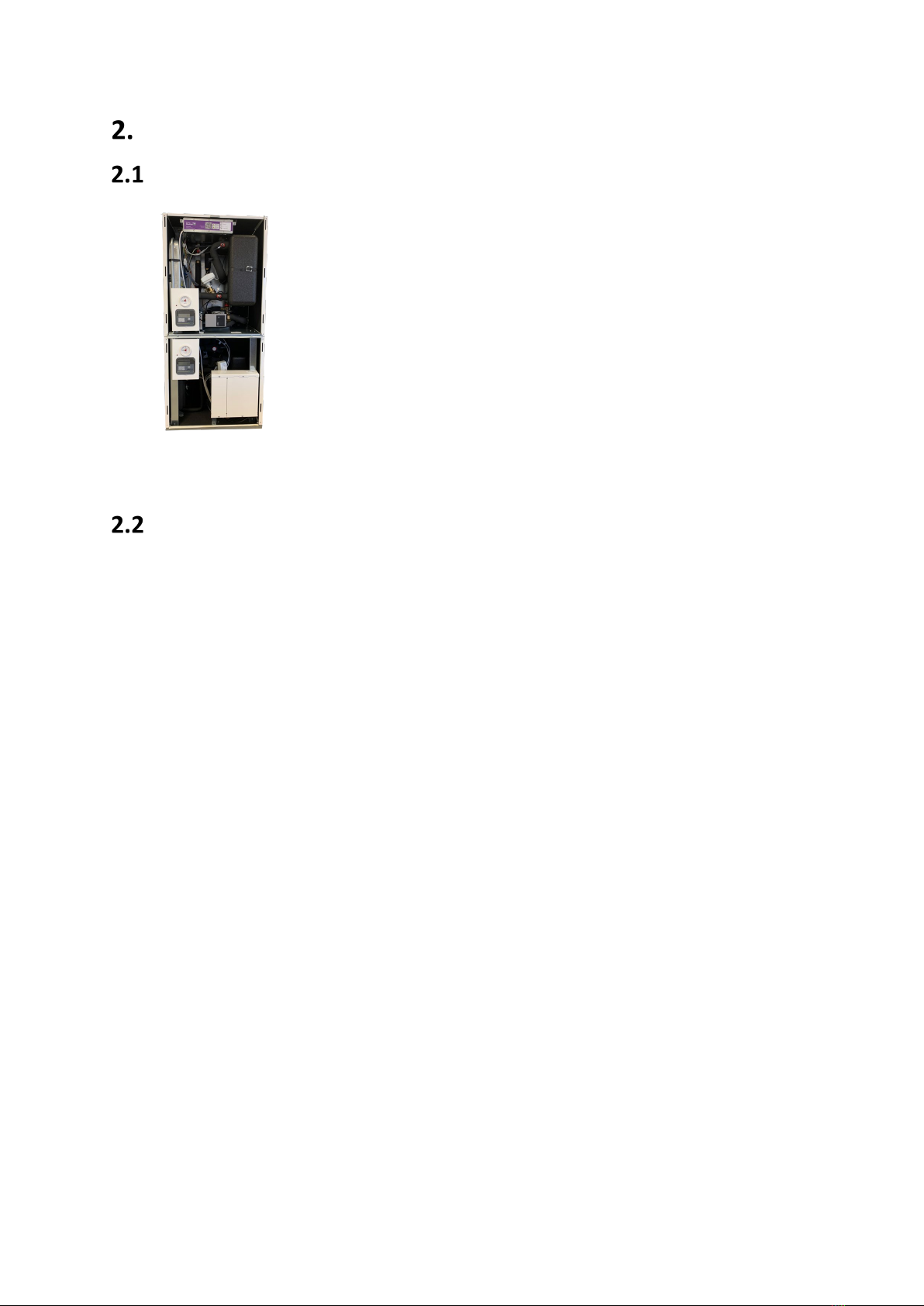
Typical ModuSat® XR & XR-ECO CHHC Unit
Note: The product may look different from the image shown.
Function and operation
District or communal heating system – the primary thermal energy is used to produce
domestic hot water and heating.
Domestic hot water (DHW) - the DHW is prepared via a plate heat exchanger. The
electronically controlled Pressure Independent Control Valve (PICV) modulates the primary
flow rate to maintain the DHW temperature. This unit operates with the DHW taking priority
over HTG – when the hot water is used it will temporarily cut the heating operation. Once
the hot water outlets are closed the heating operation will be resumed.
Heating (HTG) – when the space heating demand is requested by the end user controller,
the heating operation is started. The electronically controlled PICV is used to modulate the
primary flow rate to match the heating demand. The unit has an integrated heating
circulation pump which is switched on when the heating is on.
Keep Warm Facility – when the heat interface unit is set in the Comfort mode, the DHW
plate heat exchanger is kept warm by opening the domestic hot water PICV to heat the plate
up to comfort temperature. This cycle runs about 3-5 minutes.
District or communal cooling system – the primary chilled water flow is used to produce
cooling.
Apartment cooling – when the space cooling demand is requested by the end user
controller, the cooling operation is started. The electronically controlled PICV is used to
modulate the primary flow rate to match the cooling demand. The unit has an integrated
circulation pump which is switched on when the cooling is on.

6 2551868A
Typical Schematic (All Top Connections)
Note: Other connection arrangements are available
Components
APrimary / LTHW flow
BPrimary / LTHW return
CDomestic cold water Inlet
DDomestic hot water outlet
ESecondary heating flow
FSecondary heating return
G Connection for safety discharge
A1 Primary cooling flow
B1 Primary cooling return
D1 Secondary cooling return
E1 Secondary cooling flow
Primary Circuit Side
1Insulated plate heat exchanger
(Heating)
2Heating Pressure Independent Control Valve
(PICV) with actuator
3Insulated plate heat exchanger (Domestic
Hot Water)
4 DHW Pressure Independent
Control Valve (PICV) with actuator
5Heat meter
C1 Insulated plate heat exchanger
(Cooling)
C2 Cooling Pressure Independent Control Valve
(PICV) with actuator
C5 Cooling meter
DHW Secondary Side Circuit
6 Flow sensor
Heating Secondary Side Circuit
7 Heating expansion vessel
8 Pressure sensor
9 Pressure relief valve
10 Pressure gauge
11 Heating circulation pump
12 Safety UFH thermostat (optional)
Cooling Secondary Side Circuit
C8 Cooling expansion vessel
C9 Pressure sensor
C10 Pressure relief valve
C11 Pressure gauge
C12 Heating circulation pump
Controls & Other Items
13 Electronic control board
14 ViewSmart room controller (optional)
15 Strainer & IV assembly
16 Filling loop (External)
S1, S2 – temperature sensors as a part of the heat
meter
S3 – DHW temperature sensor
S4, S5 – heating flow and return temperature
sensors
CS1, CS2 – temperature sensors as a part of the
cooling meter
CS4, CS3 – heating flow and return temperature
sensors

7 2551868A
Technical Parameters
Electrical
Electric supply
220 / 240 Volt (AC)
Frequency
50 Hz
Current absorption
0,6-1 Amps
Hydraulic connections
Type 1
Types 2 & 3
Type 4
Primary LTHW flow
A
3/4 “
3/4 “
3/4 “
Primary LTHW return
B
3/4 “
3/4 “
3/4 “
DCW inlet
C
3/4 “
3/4 “
3/4 “
DHW supply
D
3/4 “
3/4 “
3/4 “
Secondary heating flow
E
3/4 “
3/4 “
3/4 “
Secondary heating return
F
3/4 “
3/4 “
3/4 “
Drain
G
1/2 “
1/2 “
1/2 “
Primary cooling flow
A1
3/4 “
1”
1 1/4”
Primary cooling return
B1
3/4 “
1”
1 1/4”
Secondary cooling flow
C1
3/4 “
1”
1 1/4”
Secondary cooling return
D1
3/4 “
1”
1 1/4”
Type 5
Type 6 & 7
Type 8
Primary LTHW flow
A
1”
1”
1”
Primary LTHW return
B
1”
1”
1”
DCW inlet
C
1”
1”
1”
DHW supply
D
1”
1”
1”
Secondary heating flow
E
1”
1”
1”
Secondary heating return
F
1”
1”
1”
Drain
G
1/2 “
1/2 “
1/2 “
Primary cooling flow
A1
3/4 “
1”
1 1/4”
Primary cooling return
B1
3/4 “
1”
1 1/4”
Secondary cooling flow
C1
3/4 “
1”
1 1/4”
Secondary cooling return
D1
3/4 “
1”
1 1/4”
See section 8 for CHHC model types

8 2551868A
Hydraulic characteristics
Pipework material
Copper
Plate heat exchanger material
Stainless steel 316L
Operating medium
Water
Primary circuit max pressure
16 bar
Primary minimum differential pressure
0.5 bar
(May vary depending on the required output)
Primary maximum differential pressure
4 bar
(May vary depending on the required output)
Apartment heating circuit recommended cold fill
pressure
1 bar
Apartment heating maximum pressure
3 bar
Apartment heating expansion vessel size
8 L
Apartment cooling circuit recommended cold fill
pressure
1 bar
Apartment cooling maximum pressure
3 bar
Apartment cooling expansion vessel size
8 L
DHW max pressure
10 bar
DCW min pressure
1.5 bar
Max primary supply temperature
85°C
Weight
Dry
Wet
CHHC XR ECO 55-10A-R40
74 kg
79 kg
CHHC XR ECO 70-10A-R70
86 kg
93 kg
CHHC XR ECO 100-10A-B50
104 kg
113 kg
For other models please contact Evinox.

9 2551868A
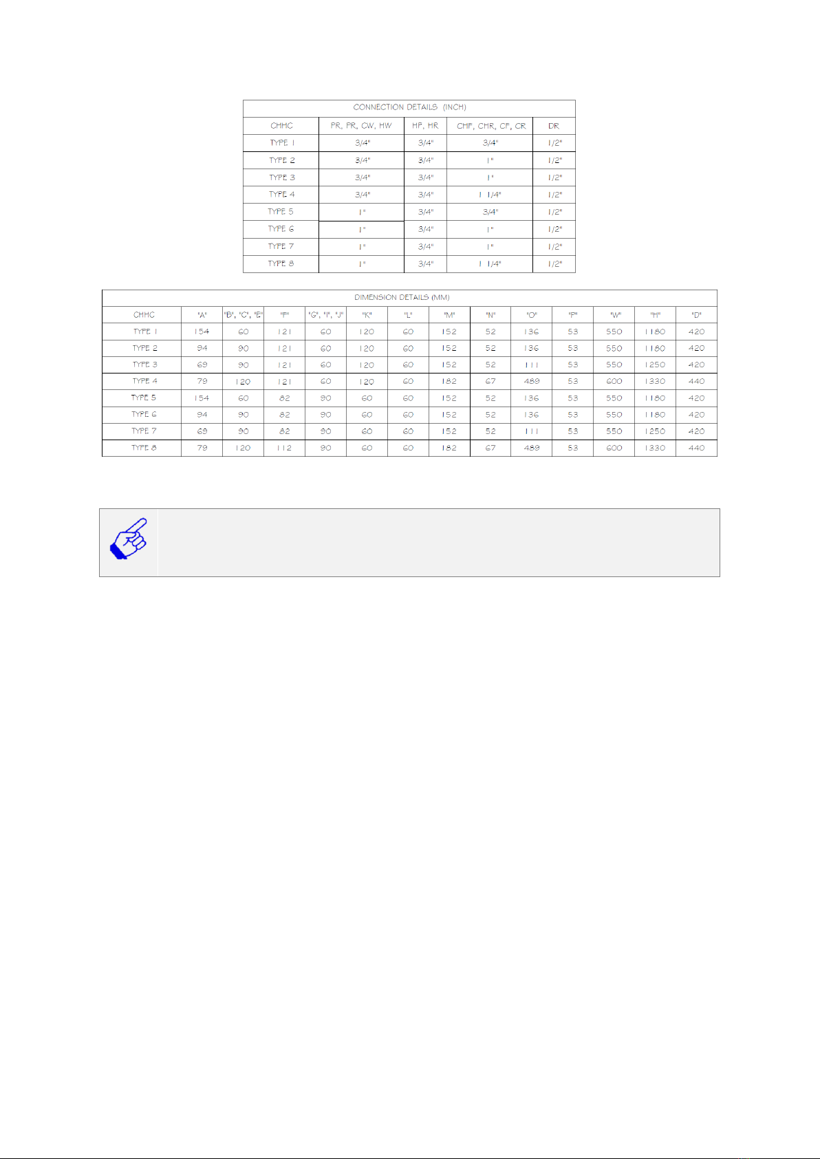
Typical Dimensions
10 2551868A
See section 8 for CHHC model type
Minimum space requirements for access and servicing: Top: 250 mm (To allow for H-type
flushing by pass), Front: 700 mm, Side: 50 mm. Flushing by pass kits for 1 1/4” are not supplied by
Evinox, installer must ensure that there is enough space for the 1 1/4” kit.
Please Note: Flushing bypass to be installed on primary connections A & B and A1 & B1.
11 2551868A
INSTALLATION
The Evinox combined heating, hot water and cooling unit must be installed, commissioned and
maintained by qualified and competent personnel in accordance with this document as well as
national regulations and standards.
Handling
The unit should be moved into position before lifting still within its packaging to prevent any
damage whilst being positioned. Only once it is safely situated, the unit should be removed
from its packaging and lifted into position.
The ModuSat® unit may have been transported and handled many times prior to the
installation, therefore it is vitally important that all unions and connections are checked and
tightened as required. In case of damage please contact Evinox Energy on 01372 722277.
Packaging materials must be disposed in accordance with the requirements of the
construction site or the property.
Lifting.
Take care when lifting this appliance. It is recommended that at least two people
perform the lifting.
Leave caps over the connections.
Ensure that the protective cover (caps) over the ModuSat® pipe connections are
kept in place to prevent ingress of any debris.
Positioning
The heat interface unit should be installed in a sheltered environment and is not suitable for outdoor
installation. It is recommended that the surrounding environment conditions do not exceed 40 °C
with the relative humidity from 15% to 85%.
Note: As the unit contains water, to operate, it is recommended not to place electrical devices, such
as control boards and other devices, underneath the unit in the case of a water leak. The
manufacturer cannot accept any responsibility for goods damaged in such a way.
Maintenance space.
It should be ensured that a sufficient space around the unit is provided to allow
the future maintenance and servicing of the unit. The removal of the front panel
should not be restricted. See section 2.5 for the minimum space requirements

12 2551868A
Hydraulic connections
Connection arrangement.
Ensure that the hydraulic connections of the pipework piped up to the unit are
correct and follows the hydraulic schematic. The manufacturer cannot accept any
responsibility for any damage caused to the unit due to crossed connections.
Any Evinox engineer callout/visit due to this issue will be chargeable.
The ModuSat® heat interface unit is designed to be wall mounted or floor standing with the typical
primary connections and domestic water hydraulic connections as shown below.
The Evinox Energy flushing by-pass valve kit should be installed before connecting the unit to the
network. Isolation valves should not be opened until system is flushed.
The whole primary system should be cleaned and flushed in accordance to BG29/2012 before
installing the heat interface unit to ensure the ModuSat® unit is not damaged.
Wall fixing
There are two ModuSat® CHHC unit configurations: floor standing or
wall mounted. Wall mounted HIU can be installed on the wall bracket or
wall frame, both provided by Evinox.
Wall bracket
Wall frame
Wall fixing
Installer must ensure that appropriate fixings are used.

13 2551868A
Evinox Flushing By-pass Kit
Evinox flushing by-pass kit allows to isolate HIU from the network during cleaning and flushing the
system. The kit includes an H shape by-pass with an inbuilt extended isolation valve, 1 strainer and 5
isolation valves.
Evinox ModuSat® flushing kit for heating circuit
Close valves
Before connecting flushing by-pass kit to the HIU ensure all isolation valves are
closed. Valves can be opened after LTHW system has been flushed.
Evinox ModuSat® flushing kit for cooling circuit
Close valves
Before connecting flushing by-pass kit to the HIU ensure all isolation valves are
closed. Valves can be opened after the system has been flushed.
1 1/4" valve kit
Evinox only supply 3/4" and 1” valve kits. 1 1/4" kits need to be purchased
elsewhere.

14 2551868A
Flushing Primary Circuit
Before filling ModuSat® heat interface unit. The primary
system should be cleaned and flushed in accordance to
BG29/2012
To open the by-pass:
Ensure both isolation valves are closed as shown in the
picture.
Use a suitable screwdriver or other tool to twist the
screw on the H-shape by-pass valve into the open
position.
Close the bypass after flushing is complete.
Provide isolation valves and a strainer.
If Evinox valve kit is not used, it must be ensured that other isolation valves provided.
Strainer on the primary inlet protects internal components from debris and sediments.
Tighten the connections.
When connecting the ModuSat® heat interface unit, ensure that all the connections are
tightened to avoid any leaks.
First fill of the HIU
Clean and flush the system before connecting the unit.
Filling the system should be performed only after the system has been fully
flushed and cleaned. Poor water quality may cause failure of the operation of the
unit.
Water quality.
It is recommended that the flushing and cleaning of the primary circuits, domestic
water circuit, secondary cooling and heating circuits is performed by a qualified
person in accordance with current standards, regulations and BSRIA guidelines.
In the case of a water leak.
Take caution of hot water
Slowly close the isolation valves at the top or bottom of the unit
Contact Evinox Energy
The ModuSat® pump should not be used for flushing.
The pump is integral to the unit and should not be used for flushing and cleaning
the system. Failure to meet this requirement will invalidate the warranty.

15 2551868A
Filling the primary circuit
Please take care when filling the ModuSat® unit.
Make sure that the by-pass valve is
in closed position
Slowly open the isolation valves on
the primary circuit.
Visually check that there are no
leaks. Tighten the connections of
the valve kit if necessary.
If there is a leak internal to the unit,
ensure the isolation valves are left
in a closed position.
HIU Flushing
Clean and flush LTHW system before flushing through the HIU
Filling the system should be performed only after the system has been fully
flushed and clean. Poor water quality may cause failure of the operation of the
unit.
First fill of apartment heating and cooling systems
The ModuSat® CHHC unit is fitted with 2 pressure gauges that are mounted on the front panel.
Gauge reading should be used when filling the secondary circuits. An external filling loop should be
used for filling the secondary circuits with the mains cold water.
Open the isolation valves on the filling loop.
Cold fill should be done to about 1 bar
Once the required pressure is reached, close the filling loop
ball valve, vent the system and repeat it again.
Disconnect filling loop.
16 2551868A
Water treatment
The quality and cleanliness of the water within both the primary and secondary circuits is vitally
important to prevent damage to the ModuSat® components, and to ensure that the efficiency and
service life of the unit is maintained.
It is therefore necessary to fully flush and treat both primary and secondary circuits using suitable
water treatment chemicals.
Water treatment in accordance to these instructions.
Please confirm with the water treatment consultants that the chemicals used and
cleaning method statement complies with the requirements set out in this
section.
Water quality may damage the unit.
Poor water quality may damage the components used in the unit and invalidate
the warranty. The manufacturer cannot take responsibility for any damage of the
unit caused by poor water quality.
Chemical cleaning and dosing.
Chemical cleaning and dosing of the system should be in line with the current
regulations, standards and guidelines. Which are, but are not limited to:
BSRIA Application Guide BG29/2012
BS7593:2006
Requirements of your local water authority
The Water Industry Act 1991, Section 119
HSE The Control of Legionella 1991
HSC Approved Code of Practice and Guidance HSG274, Part 2
Water Quality Guidelines
TH - Total hardness is caused by calcium
and magnesium.
pH – this measures the alkalinity of the
water, neutral alkalinity is pH7. Heating
systems require an alkaline pH. Lower
pH will increase the corrosion risk.
TDS – dissolved solids in the system and
is a measure of the cleanliness of the
water (satisfactory level should be
within TDS of 10% of the mains water) .
Conductivity – this is the measure of the
ability of water to pass an electrical
current.
Free copper – the level of copper in the
system.
Total Iron and Manganese – this
measures iron concentration in mg/litre.
These are strong oxidants and may
increase the risk for corrosion.
Recommended
Hardness (TH)
Up to 150 mg/l (as CaCO
3
)
Chlorides (Cl-)
Up to 150 mg/l
PH
7.5 – 9.0
Resistivity
>2000 Ohm/cm
Sulphate (SO
4
2-)
Up to 70 mg/l
Conductivity
200 crs
TDS
0-200 ppm
Free carbon dioxide
(CO2)
Up to 5 mg/l
Manganese (Mn)
Up to 0.1 mg/l
Iron (Fe)
Up to 0.2 mg/l (or 5ppm)
Copper
Up to 1 mg/l
Typical Water Quality Guidelines
17 2551868A
Visual inspection should be carried out ensuring that the water is clear, bright and free from
particulate matter. The system must be fully vented, pressurised and dosed with anti-corrosion and
anti-bacterial growth inhibitor.
High DHW temperature may cause scaling.
High operating temperatures on the domestic hot water circuit may lead to scaled
DHW plate heat exchanger. It is recommended to set the DHW temperature to
maximum of 55°C especially in hard water areas.
Dosing Secondary System
Once the system is cleaned and flushed the inhibitors should be added to the secondary side to
prevent the corrosion or bacteria growth.
A suitable long term corrosion inhibitor and inhibitor for preventing the bacteria should be
introduced in a proportion of the system volume.
Excessive filling of the secondary circuit with untreated water may lead to scale
build up and corrosion. This may damage the ModuSat® unit or reduce the
performance.
Please confirm with the water treatment consultants that the chemicals used and
cleaning method statement complies with the requirements set out in this
section.
Evinox Energy do not take responsibility for approving inhibitors used for dosing
the system.
Warranty due to Water Quality
The warranty of the ModuSat® unit is strictly related to the instructions and procedures indicated in
this manual and the warranty does not cover any damage caused by scale and/or corrosion resulting
from poor water quality.
The components and materials used in the system assembly should also be checked to ensure they
do not contribute to dissolved oxygen that can cause corrosion.
Also:-
Ensure there are no air pockets in the system
Remove gas permeable parts and materials
Ensure the expansion vessels are properly sized and the pre-charge pressure valve to guarantee
positive pressure, with respect to the ambient pressure, throughout the circuits.
18 2551868A
Electrical Connections
Risk of Electric shock.
Disconnect the electric supply before starting any works on the unit.
Qualified personnel.
Electrical installation must only be carried out by qualified personnel.
Overvoltage or lightning.
The ModuSat® unit has no protection against lightning or other overvoltage
shocks.
Power supply via un-switched double pole fused connection.
The ModuSat® requires a 220/240V (AC) 50Hz mains supply connection through
an un-switched fused connection fitted with a 3 Amp fuse (to BS1632). Extension
cords, multiple plugs, and other adapters must not be used. The device must be
earthed.
Follow the instructions
Any damage caused by an incorrect connection will invalidate the warranty.
Evinox Energy cannot accept any responsibility for incorrect wiring.
The ModuSat® wiring boards are located within the ModuSat® itself under a removable metal cover.
To access the connection board, the full front case cover should be removed. To take off the cover
the retaining screw should be removed and the cover lifted off.
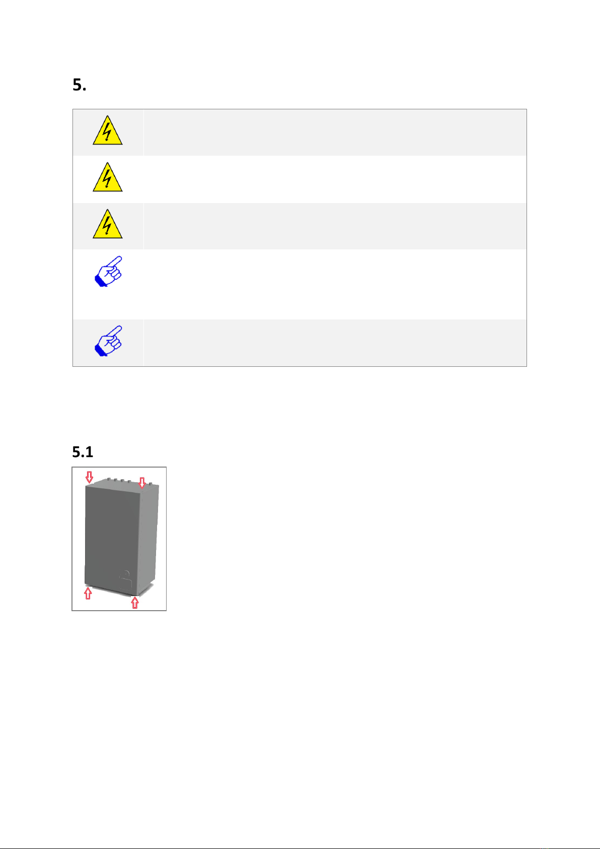
Removing the Front panel
To access the wiring board, the front panel must be removed.
On a wall-hung units the front panel is fixed with four screws – two at the
top of the unit and two at the bottom as shown opposite.
Untighten the screws and remove the panel pushing it upwards first and
then remove it towards yourself.
The panel is powder coated stainless steel. Take care when removing and
placing the front panel to ensure the surface is not damaged.
After the works are finished, place the panel on the unit and tighten the
screws.

19 2551868A
ModuSat® Wiring Connections
The ModuSat® wiring boards is located within the ModuSat® itself under a removable metal cover.
CHHC has two wiring boards, one for the heating and one for the cooling. Depending on the model,
the boards can be found in either metal boxes shown below.
To access the connection board, take off the cover. The retaining screw should be removed and the
cover lifted off. The connection board will then be accessible and all required connections can be
made simply using the clearly labelled screw down terminal connections. Guides for the various
connection applications and requirements are detailed in the wiring principle drawings shown on
pages 21-23.
The Control Board
The control board is located next to the connection board. The control board cover must
not be removed. Doing so may invalidate the warranty.
Connection Terminations
Evinox Energy strongly recommend in accordance with best practice that all wiring
connections to the board, especially the BUS and room controller are terminated using
‘bootlace ferrule’ connectors. These connectors ensure a good connection and that the
whole cross sectional area of the wiring is intact.
5.2.1 RJ45 Connections
If the TCP/IP network is used (instead of the BUS) the RJ45 must be connected to the control board.
The RJ45 connection can be found at the bottom of the control board as shown below.
Cable glands are fitted at the bottom of the ModuSat® case as shown in below:

20 2551868A
ModuSat® Connection Board
Please Note: When
connecting external
valves or pumps to the
ModuSat control board, it
must be ensured that
each connection does not
exceed 1amp @
220/240V (AC).
Table of contents
Other Evinox Recording Equipment manuals


![Novation Launchpad Mini [MK3] user guide](/data/manuals/1h/6/1h6un/sources/novation-launchkey-mini-mk3-manual.jpg "Novation Launchpad Mini [MK3] user guide")


