Evolution Aircraft REV X Manual

1
EVOLUTION AIRCRAFT INC.
REV X
Operating and Maintenance
Instruction Manual
Version 1.0
Released 04/01/2019

2
INTRODUCTION
REV X is a STOL (short takeoff and landing) single seat trike powered by a Rotax 582 with
E box. Its most notable key features are NO FRONT STRUT, All wheel suspension and it
Folds onto its REV X trike dolly cart for set up and storage in under 10 minutes.
Components used are of the highest quality and technology on the market today. From the
battery to the engine, from the bolts to the Powder Coat, only the Best of the Best is used.
The Rotax 582 engine is dual ignition, liquid cooled, with a gear box. This system has
proven to be the highest quality, best running engine in its class. The Rotax provides a
surplus of power at 65 HP for impressive climb and continuous cruise.
Stopping power comes from the Black Max Super STOL braking system utilizing 2 calipers
and 4 brake pads all on one rotor!
The suspension comes from 4 "flex rods". The entire front end is a swing arm giving the
nose wheel equal travel. The entire front end disconnects and "unplugs" to fold the trike in
lieu of a folding mast. In its folded form the rear wheels are lifted off the ground creating a
counterbalance effect which makes putting the wing up and down quite effortless.
Instrumentation comes from a super bright color display from MGL. The Xtreme EFIS
provides valuable information about the engine and flight.
Standard features include:
1. Cantilever mast with no front strut required
2. All wheel suspension
3. Quick fold cart for easy storage
4. MGL Xtreme color instrument panel
5. Tundra tires
6. Electric start and pull start
7. Earth X lithium battery
8. Dual hydraulic disc brake
9. 4130 Chrome Moly high reinforcements in high stress areas
10. Real Aircraft seat belt
11. Extra padded seat cover
12. ¾” chrome moly front axle
13. AN aircraft hardware throughout
14. Tefzel aircraft wire
15. Cannon plug for quick disconnect

3
ROTAX 582 ENGINE
DESCRIPTION
•2-cylinder
•2-stroke liquid cooled engine with rotary
valve intake
•dual electronic ignition
•integrated water pump and thermostat
•exhaust system
•carburetors
FACTS
Over 35.000 units of this popular Rotax 2-
stroke engine have been sold. This engine type
is well regarded for its easy maintenance and
robustness.
VERSION PERFORMANCE TORQUE MAXRPM
kW hp 1/min Nm hp 1/min 1/min
582 Mod. 48 65 6500 75 55.3 6000 6800
WEIGHT kg lb
engine 29.1 64.0
2 carburetors 1.8 4.0
exhaust system 5.1 11.2
electric starter 3.5 7.7
propeller speed reduction unit “B“/ i = 2.58 4.5 9.9
propeller speed reduction unit “C“/ i = 2.62/3.0/3.47/4.0 8.0 17.6
propeller speed reduction unit “E“/ i = 2.62/3.0/3.47/4.0 11.2 24.7
ENGINEDATA
ENGINETYPE582| 65 hp(UL)
BORE STROKE DISPLACEMENT
76 mm 2.99 in 64 mm 2.52 in 580 cm
3
35.4 cu. in.
FUEL MIXINGRATIO
min. MON 83 RON 91*
min. AKI 87* API-TC-Classific
at ion 1:50
or optional with fresh oil pump
* leaded, unleaded, AVGAS 100LL or Ethanol 10
AIRCRAFT ENGINES
WWW.FLYROTAX.COM © 201 BRP-Rotax GmbH & Co KG. All rights reserved. ®, TM and the BRP logo are trademarks of Bombardier Recreational Products Inc. (BRP) or its affiliates.
picture: 582 with options

4
Engine Lubrication
Oil Injection Pump
Use Husqvarna 2-Cycle Synthetic Blend Oil (Commonly sold at Lowes Home Improvement)
CAUTION:
Many 2 stroke oil brands can be used however the REV X is set up at the
factory with this oil and it is highly recommended NOT to change oils unless a
complete oil reservoir flush is done.
5
Break in Procedure

6
PROPELLER
Any running propeller can present a potential danger for the pilot, the passenger and/or
the spectators. Never let non pilots touch the propeller, even when the engine is stopped.
Always be extremely careful as soon as an engine equipped with a propeller may turn.
WARNING
Before turning the propeller with the hand, always verify attentively that the
driving ignition is off.
NOTE:
Each prop blade as well as the prop crush plate has a colored dot which must line up
for the purpose of dynamic balance.
Torque and Pitch Maintenance
Torque: 100 inch pounds
10 minutes after first assembly, engine warm.
After the first flight hour.
As many as necessary, and at minimum every 25 hours and/or every 3
months.
Before each flight:
Visual inspection of the propeller and checking of the screws.
If an incident or prop strike require repair, this must be approved by Helices E-PROPS in
its workshops, or by a specialist after discussion with the E-PROP Team.
All the blades have a reference number and a serial number. These references are
important for determining with the E-PROP team what modifications or the possible
replacement in necessary. The final checks of the propeller, and in particular balancing, are
made by Helices E-PROPS before the delivery. Any modification of the propeller can
damage the balancing and generate vibrations which could damage the engine.


8
Basic Features
Powerful 32 bit ARM processor
4.3” high resolution 480x272, sunlight readable, wide viewing angle, 600 nits TFT
LCD display
LED backlight (brightness can be adjusted for low light flying conditions)
SD Card interface for data recording, user splash screens, checklists, graphic
information pages, firmware upgrades, navigation and route files etc
1/8” NPT female fittings for Altitude and Airspeed pitot tube connections
Rotary control plus 5 independent buttons for easy menu navigation and user input
External active GPS antenna connection
Built in RTC (Real Time Clock)
Wide input supply voltage range of 8 to 30V DC
Built in voltage reversal and over voltage protection for harsh electrical
environments
Light weight design
Optional Features
Optional MGL Avionics compass sensor unit (SP2/SP6)
Optional MGL Avionics AHRS sensor unit (SP4/SP5/SP7)

9
System Overview
The RDAC (where all the sensors run to) is located behind the pilot seat just opposite of
the battery. This design keeps all of the sensor leads short and without the need of
extension cables and keeps the wiring lighter and simpler. This RDAC (brain box) is easily
accessible by removing the pilot seat by removing the 4 bolts that secure it to the frame.
NOTE due to imperfection in the seat mold, the rear left seat bolt corner has 2 washers that
shim the seat in order to make the seat perfectly straight. Be sure to reinstall these washers
when putting the seat back in Most of the sensor wires are very small gauge and can come
loose during the life of the machine. Simply retighten any loose sensor wires if a sensor
appears to fail. The RDAC is completely labeled making it very simple to figure out. The
RDAC has a green blinking light which indicates it is getting power when the key is turned
on. If it is not blinking green it is probably not getting power and will not work without
being powered. There are only 3 wires which are bundled together in a single shielded
cable that connect the RDAC to the EFIS (monitor). If an RDAC fail notice displays on the
EFIS, it is referring to a connection break between the EFIS and the RDAC or lack of power
to the RDAC. All of the parameters (VNE caution temperatures and warnings are fully
programmable under the menu settings. There are 5 different screens to scroll through,
but it is recommended to turn off 3 of the 5 screens which are not useful for the REV Xs set
up. These other screens include satellite info and artificial horizon. This leaves a screen
with large, easy to read round dials for flight instruments and a screen with mostly easy to
read bar graphs for engine monitoring. When only 2 screens display it allows the user to
use the left square button to toggle between the 2 screens instead of having to go through
all 5 screens to get back to the other useful screen.

10
Using the EFIS
Pressing the left button will scroll between screens.
Pressing the round knob in will bring up a menus. Turning the knob to highlight and then
pushing in to select will allow you to navigate the system.
Barometric pressure is located in the top right corner of the EFIS display. Turn the rotary
control to change the local pressure setting. The local pressure can be displayed in “mB”or
in “HG”. This is used to set the altimeter to MSL or AGL.
NOTE:
This must be checked and adjusted before each flight in order for it to be accurate.
CHT (cylinder head temperature) and EGT (exhaust gas temperature) alternate in the
same location. CHT must remain below 270°F and EGTs must remain below 1200°F.
Coolant must remain below 175°F. These are important to monitor. If one of these
temperatures goes too high a red WARNING box will appear and flash on the screen.
Tachometer is displayed on the right side of the screen. Full throttle should yield between
6300-6700 RPM.
Airspeed may or may not be accurate and needs to be calibrated. Using the GPS and
making different headings comparing the GPS to the airspeed it is possible to calibrate the
airspeed. We recommend your airspeed be set to 120% as a base value to get closer to a
correct reading. The value can be adjusted up to 150%.
The Ground Speed is labeled GS EFIS display. The ground speed value will only be
displayed when a valid 2D or 3D GPS fix has been achieved.
VSI is vertical air speed or the rate in which climbing or descending. “+” means it is
climbing an “–“means it is descending.
Hobbs Meter tells the number of hours on the engine which is important for scheduled
maintenance.
Voltage shows the battery voltage when the engine is off and the charging voltage when
the engine is running. Keep in mind the voltage is higher (13.1-13.6 volts) than expected
lead acid battery voltage.

11
Wing
For complete instruction manual click here:
http://northwing.com/Mustang3-Wing-Manual.pdf
Braking System
WARNING
This system does NOT use brake fluid.
The brake system is a combination of a Matco master cylinder which uses an internal
“intensifier kit” with a black Max caliper system.
Bleeding the brakes should be done by pressure bleeding the system with ATF (automatic
transmission fluid). Fluid should be added with some form of a pressurized container
(pump sprayer or oil can) with a hose that secures firmly around the lowest bleed screw
on the caliper. Loosen Allen set screw at top of caliper to allow all air to escape from the
system as ATF fluid is injected into the lowest bleed on the caliper. When all air has
escaped, tighten the top bleed screw. Then loosen the large set screw in the top of the
Master cylinder and continue to pump ATF fluid into the caliper until all the air is out of
the master cylinder. Then tighten large setscrew and the bleed screw supplying the ATF
fluid. Ensure the brake pads are not dragging by elevating the nose wheel and spinning the
wheel. If the wheel does not spin freely, loosen the large setscrew in the master cylinder
while pressing the brake pedal down until a small amount of fluid leaks out. Then tighten
the setscrew and test again. Once the wheel spins freely make sure the pedal is hard and
not spongy
CAUTION:
Tightening the setscrew may cause the caliper to activate the brake pads.

12
Replacing the Brake Pads
1. Elevate the front wheel by putting something under the frame such as a stool with
padding
2. Loosen all 8 Allen head screws in the triple trees (horizontal CNC fork tube clamps)
3. Once fork tube and nose wheel are free, remove the bolt that go through the port
(left) side of the axle
4. Remove the through bolt that secures the caliper to the axle
5. Loosen the setscrew that tightens the caliper to the axle
6. Slide the caliper with the free floating rotor off the axle
7. Separate the rotor from the caliper
8. Remove the piston side brake pad first and then the other
9. Install new pads and reverse steps for reassembly
Support Cables
The 5 support cables on carriage can be removed easily by locating which nut to remove
first. The angle of the bolts that secure the cables are orientated in such a way that as one
of the nuts is loosened it will relax the cable being removed. The tension of the cables is
controlled by twisting the cables. Twisting counterclockwise tightens the cable by
shortening its overall length and clockwise loosens it. This tensioning method is effective
and lighter and simpler than adding a tensioning mechanism. When replacing a cable try
and get the cable snug so that it is difficult to expose only 3-4 threads on the bolt that
secures it. Start the nut by hand onto the 3-4 threads and then carefully tighten down the
nut with a 7/16” socket and wrench which will start to tension the cable even further.
When the nut is all the way down the cable should be extremely tight.
CAUTION:
The X brace behind the pilot seat must be done at the same time in order to not
rack (shift) the frame.

13
EARTH X BATTERY
WARNING
Do NOT charge with a desulfinating battery charger.
Do NOT use Schumacher battery chargers with Earth X batteries.
Recommended to Use the simple noncomputerized 1-2 amp battery charger. These
are readily available as the cheapest chargers on the shelf at Walmart and auto part
stores.
Model: ETX12A
Nominal Voltage
13.2 V
Ah (Lead-acid equivalent)
12
Ah (1 hour discharge rate)
4 (1C rate)
Pulse Crank Amps (PCA)
220A (3 sec @ 25 °C, voltage >9V)
Cold Crank Amps (CCA)
135A (modified SAE test, 3 sec@ 0°F, voltage
>7.2V)
Max Continuous Discharge Amps
40A
Standard Charge Voltage
13.9 - 14.6 V
Maximum Charge Voltage
15 V
Recommended Charger/Maintainer
Amps
.8 - 5A
Max Charge Amps
20A (from vehicle charging system)
Life (Charge cycles)
4000 cycles @ 1C discharge rate, 25°C (20%
depth of discharge)
2000 cycles @10C discharge rate, 25°C (80%
depth of discharge)
Life (Years)
8 Years
Weight
1.3 lb. (.6Kg)
Dimensions
4.5in x 2.6in x 3.7in (113mmX66mmX95mm)
Environmental Rating (resistance to
water intrusion)
IP 66 (wash down with a high pressure washer)
Operating Temperature
-30 °C to +60 °C
Storage Temperature
-40 °C to +70 °C

14
List of Chargers
Model
Safe to
Use
BMS
Reset
Suggested Use
TecMate/
Optimate
Lithium TM-
271/TM-291
Yes
Yes
Use as charger, maintainer and it will
reset EarthX’s BMS over-discharge
protection
TecMate/
Optimate
Lithium TM-
271/TM-485
Yes
Yes
Use as charger, maintainer and will
reset EarthX’s BMS over-discharge
protection
Battery
Minder
Any model
No
No
Do not use, as full time de-sulfating
mode will damage a lithium battery
Black N
Decker
BM3B
Yes
No
Use as charger
Black N
Decker
BC15BD
No
No
Do not use, as full time desulfinating
charger
Christie
All Models
No
No
Do not use, as full time de-sulfating
mode will damage a lithium battery
CTEC
Lithium US
Yes
Yes
Use as charger, maintainer and it will
reset EarthX’s BMS over-discharge
protection
Deltran
Battery Tender Jr
Yes
No
Use as charger, maintainer, but will not
reset EarthX’s BMS over-discharge
protection
Deltran
Battery Tender
(original)
Yes
No
Can be used for charging only.
Maintenance voltage is too low.
Deltran
Battery Tender
Plus
Yes
No
Can be used for charging only.
Maintenance voltage is too low.
Duraboost
Duraboost 750
Yes
No
Can be used for charging. Cannot find a
maintenance voltage in manual so if it is
less than 13.3V, too low.
Duraboost
Duraboost 1000
Yes
No
Can be used for charging. Cannot find a
maintenance voltage in manual so if it is
less than 13.3V, too low.
H-D
Tender Jr
Yes
No
Use as charger, maintainer, but will not
reset EarthX’s BMS over-discharge
protection
Moose
Tender Jr
Yes
No
Use as charger, maintainer, but will not
reset EarthX’s BMS over-discharge
protection

15
NOTE:
This is not an all-inclusive list.
Lithium batteries have a very low self-discharge rate which means the battery, if
disconnected from your trike, could “hold its charge” for a year.
The ETX Lithium battery is compatible with most “modern” lead-acid battery chargers or
4cell LiFePO4 battery chargers. By “modern” we mean a charger that automatically turns
off when the battery is fully charged, a charger with a micro-processor, or a charger with
multiple mode charging. The “full charge” voltage for the ETX Lithium battery is 13.3V or
higher. Some lead-acid battery trickle chargers maintenance mode voltage can be below
13.3V, which is too low for a lithium battery. For example, the Battery Tender JR has a
maintenance mode voltage of 13.3V which is compatible, whereas the original Battery
Tender has a maintenance mode voltage of 13.2V which is too low for a lithium battery.
Never charge a faulty battery (a battery that will not accept a charge or hold a charge).
Never use the de-sulfate setting on your charger. Be sure the charger’s output voltage level
does not exceed 15V. If the charger does not display the voltage reading, then use a
voltmeter to check the voltage while charging. If the battery gets hot while charging,
discontinue charging and use. Do not charge battery in temperatures above 140°F (60°C),
NOCO Genius
All Models except
the lithium
specific one
No
No
Do not use, as full time de-sulfating
mode will damage a lithium battery
Tenergy
4cell LiFePO4
Smart Charger
Yes
Yes
Use as charger, maintainer and it will
reset EarthX’s BMS over-discharge
protection
ODYSSEY
Ultimizer
Yes
No
Use as charger and maintainer
Pulsetech
Xtreme XC100
Yes
No
Can be used for charging only. While in
operating, verify the pulse output is off.
TecMate/Opti
mate
All lead acid
charger models
No
No
Do not use, as full time de-sulfating
mode will damage a lithium battery
CTEC (like
Multi XS
3600)
All lead acid
charger models
No
No
Do not use, as full time de-sulfating
mode will damage a lithium battery
Schumacher
Any model
No
No
Do not use, as full time de-sulfating
mode will damage a lithium battery
Yuasa
Smart Shot 900
No
No
Can be used for charging. Cannot find a
maintenance voltage in manual so if it is
less than 13.3V, too low.
Yuasa
Smart Shot
1.5mA
No
No
Do not use, as full time de-sulfating
mode will damage a lithium battery

16
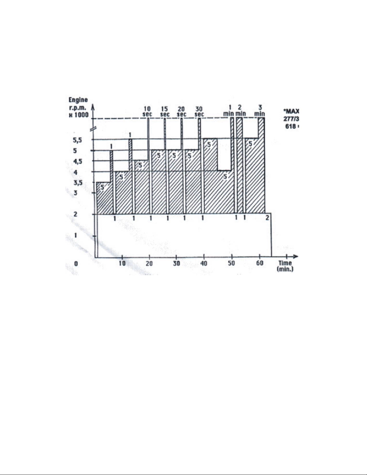
or in direct sunlight. When charging a battery, place it on a non-flammable surface, and
remove any flammable items nearby. For maximum battery and vehicle starting system
life, do not crank an engine for more than 10 seconds within any 1 minute period.
Troubleshooting
The ETX Lithium battery is an extremely reliable battery with a longer useful life than
comparable lead-acid batteries.
Despite the high reliability, you may encounter situations where the battery does not
operate as expected. Here are some potential issues you may encounter with the
appropriate troubleshooting procedures.
Problem
The charger shuts down during the first few seconds of charging.
Possible Causes and Solutions
Are you using a Constant Voltage (CV) charger? CV chargers may trip when first connected
to a drained battery due to a high inrush of current. If this happens, reset the charger and
try again. If the problem continues, try using a different charger.
Problem
Zero voltage at the terminals or un-stable voltage (voltage reading drifts slowly to zero).
With a lead-acid battery, finding a very low voltage at the terminals often indicates the
battery has reached the end of its life. With an ETX Lithium battery this may not be true.
Possible Causes and Solutions
The ETX series lithium battery has built-in over-discharge protection circuitry, which
automatically disconnects the battery if the voltage drops below 11.5 volts (98%
discharged). When the battery is “disconnected”, the voltage at the battery terminal should
be zero.
Some volt-meters may initially indicate a voltage, but it will decay to zero within ten
seconds or so. For a drained battery, simply connect the battery to a charger to restore
charge (charge with 2A for 20-30 minutes), and then re-check the voltage. If the voltage is
12.8V or greater, the battery should be ok and can be fully charged. Not all chargers will
charge a battery that displays zero volts, so check our website for a list of compatible
chargers, and specifically chargers that will work for recharging an “over-discharged”
battery for which the BMS’s over-discharge protection has activated. This condition is
sometimes referred to as a BMS reset.

17
Problem
The battery seems to suddenly stop working.
Possible Causes and Solutions
A lithium battery voltage remains relatively constant while discharging, but when the
battery runs out of power it does so abruptly. Try charging the battery for 30-60 minutes
at 1 –2 Amps. If the battery still does not work, or the measured voltage is less than 12V,
the battery may be permanently damaged and needs to be replaced.
Problem
The battery does not hold a charge.
Possible Causes and Solutions
There may be a problem with the engine charging system: While the charging system is in
operation, it should output approximately 13.9 -14.6 volts. If the voltage is below this level,
the charging system needs to be repaired.

18
FOLDING THE TRIKE
1. Disconnect throttle and wiring.
2. Lift nose wheel and slide the cart underneath the REV X.
3. Use bungee cord to lift the front of the cart and attach it to the swan catch to help
line up pins that secure cart to frame.
4. Install 2 cart/frame pins.
5. Release bungee cord and allow cart to lock its rear wheels against drag links of the
REV X’s suspension.
6. Secure control bar into the chalices of the cart.
7. Remove front end of trike by removing the 2 speed pins that hold it on.
8. Lower the cart to the ground.
9. Remove the tip battens.
10. Fold in the sprogs.
11. Loosen the haul back cable.
12. Remove all battens except for the nose battens and the longest root battens
13. Ensure the prop is vertical and Ensure engine is cool to the touch.
14. Fold wing back (Chock wheels on dolly cart for ease) Either using 2 people walk the
tips back towards each other or connect both ends of a 40’ rope to each wing tip
strap and pull the center of the rope back for single person folding.
15. Once the wing is folded, carefully pull the fabric up and over to the outside of the
folded wing.
16. Insert wing standoffs between the cross tube and the roll cage mast at the very rear
of the trike.
17. Roll up fabric and secure with straps.
18. Secure front end in cart for storage.
19. Tie wings together to press and hold the wing standoffs in position.

19
Click the link below to watch a video on how to fold the Rev X trike.
https://youtu.be/zLQO0Ci-JaQ

20
OWNER MANUALS
ENGINE
https://www.cps-parts.com/cps/pdf/d04495.pdf
MAINTENANCE MANUAL
https://www.cps-parts.com/cps/pdf/d00288.pdf
Illustrated PARTS CATALOGUE
https://www.cps-parts.com/cps/pdf/d05246.pdf
MGL Xtreme EFIS
http://mglavionics.com/html/xtreme_efis.html
WING
http://northwing.com/Mustang3-Wing-Manual.pdf
PROPELLER
https://ppg.e-props.fr/docs.php Click on NG-D Propellers –pdf file
In case of incident, please contact Helices E-PROPS as soon as possible at:
Hlices E-PROPS Arodrome de Sisteron 04200 Vaumeilh – France 33 (0)4 92 34 00 00
FOLDING THE WING
https://youtu.be/zLQO0Ci-JaQ
Table of contents


