Santana Tandem Installation instructions

1
Tandem disassembly
Required tools
•4, 5 and 8 or 10 mm Allen wrench
•Pin-spanner tool to tighten the chain if necessary (e.g. Park-Tool SPA-1)
•S&S coupling wrench (no longer needed with the new Z-couplings)
Disassembly
1. If the tandem is equipped with extras such as racks, lowriders, mudguards or bottle mounts on the stoker lateral tube,
these are removed first.
2. The first step is to disconnect the shift cables and the rear brake cable at the cable
couplers under the bottom tube. To remove the tension from the cables, it is
recommended to switch gears to the smallest sprocket at the front and rear.
3. Then remove the barrel adjuster on the down tube (unscrew them on older models)
to adjust the cable. separate the cables from the frame. If the tandem is equipped
with an electric shifting system, only the plugs on the head tube, respectively at the
display and on the captain and stoker bottom brackets are disconnected.
4. Now the captain handlebar is separated from the frame.
a) To do so, first unhook the front brake (V-brake) and unscrew the brake caliper, still attached to the brake cable,
with a 5 mm Allen wrench. Then screw the screw back into the thread to avoid losing it. Alternatively, the brake
cable can also be loosened from the brake caliper by unscrewing the 5 mm Allen screw (Note: When
reassembling, the brake may need to be adjusted again). For a caliper brake, the brake caliper is loosened and
the sleeve nut (5 mm Allen) on the back side of the fork crown is unscrewed in succession the entire brake caliper.
b) To remove the handlebars, first loosen the stem bolts (4 or 5) on the side of the steerer tube and then remove the
headset cap by unscrewing the center 5 Allen screw.
c) Afterwards, screw the cap of the headset back into the steerer tube to avoid losing it.
d) The handlebar bolts (4/5) on the disassembled handlebar can be loosened so that it can later be placed flat
and space-saving in the case.
5. Now the tandem is flipped over so that it stands on the saddles, while the handlebar of the stoker keeps the tandem
from tipping over sideways.
6. Next, remove the front wheel and the rear wheel by loosening the quick release/ thru axles. Remove the quick release
from the wheel hubs, as these will be packed separately later.
7. Loosen the cranks of the timing chain with an 8- or 10-mm Allen wrench. The chain and the belt are removed at once.
Tip: with the belt drive, the position of the cranks on the belt and the belt blades can be marked with a colored
marker pen. This makes it easier to find the synchronized crank position when assembling.
8. Then remove the cranks on the other side.
9. The chain can be left on the frame. However, the chain stay should be protected from paint scratches with a
protective pad and the chain should be fixed with 2-3 more Velcro pads. If a carrier is packed, the rear derailleur
must be removed from the frame. If knowledge with chain locks are available, SRAM, KMC or Shimano 11-speed
chains can also be disassembled.

2
10. Now the frame is separated at the couplings. For the new Z-couplings, only a 5 mm Allen wrench is needed to release
the couplings, while a special S&S wrench is needed for the older S&S couplings.
a) First remove the bottom tube out of the tandem frame by loosening the 5 mm Allen screws on the underside of
the bottom tube until it can be removed from the frame.
b) Then loosen (the lateral) and the top tube at the couplings on the side of the captain seat post. The front and
rear sections can now be separated.
c) Finally, remove the remaining couplings from the rear frame.
11. Remove the captain and stoker saddles, including the seat posts. (Tip: Mark saddle height with a marker on the saddle
tube attachment. This save having to adjust the saddle height when reassembling later).
12. Now the handlebar of the stoker is loosened from the stoker stem with a 5 mm Allen wrench. (Tip: The position of the
handlebar can also be marked with a marker. This save having to re-adjust the correct handlebar position when
reassembling). At the removed handlebars still loosen the handlebar bolts, so that it can be stored flat and space-
saving in the case.
13. Now the packing into the tandem case takes place. First, remove the foam layers 2-6 (these are numbered at the
top right).
Packing into the Santana SafeCase
First remove the foam layers one by one and place them on top of each other. The bottom foam layer (1st layer) remains
in the case.
Layer 1
•Bottom tube (+ lateral tube)
•Quick release / thru axles front and rear
•Stoker handlebars
•Stoker cranks and the left captain crank (SPD
pedals do not need to unscrew).
Layer 2
•Captain crank
•Place the captain frameset with the fork facing
upwards (if necessary, pad the right brake caliper
so that the down tube does not get scratched
and put a protective cap on the bottom bracket
axle facing upwards).
•If the tandem is equipped with a rack, this is now
inserted with the left side at the lower end, under
the foam of the 2nd layer, while the upper side of
the rack rests against the edge of the case. The
foam must be cut out at the required points for
this purpose.

3
Layer 3
•Insert the rear wheel with the cassette facing upwards
(with 32 mm tires, the air must be released).
Layer 4
•The captain handlebars turned upside down with the
stem previously loosened and turned 180°. Brake
levers point to the edge.
•Roll up the cables and place them safely in the
handlebar cutout.
Layer 5
•Place the rear frame with the rear derailleur facing
down. Pad the cassette towards the chainstay and,
if necessary, rotate the rear wheel underneath
slightly so that the rear derailleur finds room
between the spokes.
•Captain and stoker saddle
•Push the front wheel with released air into the rear
frame (like installing the rear wheel).
Layer 6
•Top tube
•Plastic box with tools (a belt can be placed loosely in
the case).
•Optional: place lowrider in a recess previously cut into
the foam in the upper left corner.

4
Tandem assembly
1. First remove all parts and foam layers (tip: stack them in the order in which they are
removed).
2. To begin, insert the Stoker handlebar into the Stoker stem on the captain seat post,
fix it with the 5 mm bolts on the side and tighten the 4 mm bolts on the handlebar.
Caution! Do not overtighten to avoid damaging the handlebars.
3. Then insert the captain seat post into the captain seat tube, fix it and place the front
frame on the captain saddle and stoker handlebars.
4. Next, loosely screw the bottom tube to the front frame. For S&S couplings, it is
recommended to screw the top tube and lateral tube to the front section first. For
the lateral tube, the tube end with the smaller distance to the bottle mount is
positioned at the rear. If the tandem is equipped with a rim brake at the rear, care
should be taken to position the cable guide correctly on the top tube. The cable
guide would then be located at the rear left of the top tube in the direction of travel.
5. Now the Stoker saddle is inserted into the rear triangle, turned around and
connected to the bottom tube. The Stokers handlebars keep the tandem from
tipping over sideways. With S&S couplings, instead of the bottom tube now the top
and lateral tube is connected to the rear.
6. Only now the top tube is inserted between the rear and front frame sections. For S&S
couplings, the bottom tube is inserted in this step. Only when all
tubes are in place the 5 mm Allen screws in the Z-couplings are
tightened to approx. 8 Nm (a coupling wrench is required for S&S
couplings). This prevents unwanted tensions caused by uneven
tightening of the screws.
7. Next, the cranks are mounted. The length of the crank tells you
which of the left cranks belongs to the captain and which to the
stoker. The captain crank is 5 mm longer than the stoker crank.
a) At the beginning, the rear chain is placed on the chainring of
the Stoker crank. The crank is screwed onto the bottom bracket axle
with an 8mm Allen key. Make sure that the notches on the inside of
the crank fit onto the notches on the bottom bracket axle. The
crank is now tightened until you feel a sudden, strong resistance
(about 30 Nm!).
b) Next, the cranks of the timing belt/chain are attached offset by
180°. If the tandem is equipped with a belt, it should already be on
the belt blade when the cranks are screwed on and the cranks
should be lined up synchronously with each other. Alternatively, the belt
can also be fitted after the cranks have been screwed on, but must then
be adjusted to the correct tightness via the eccentric using the Pin-
spanner tool (it should be possible to press the belt in slightly by about a
finger's width). A timing chain can be fitted after the crank has been
mounted.
c) Finally, screw the right Captain crank to 180° offset to the already
mounted cranks of the timing drive.
8. Next, the quick-releases are inserted into the hubs and placed in the fork and
rear triangle. The lever of the quick release is located on the side of the disc
brake. On the front wheel, the lever is also on the side of the rear resp. front disc brake. Always close the lever (with
resistance from a position of approx. 45°) in the opposite direction to the direction of travel.

5
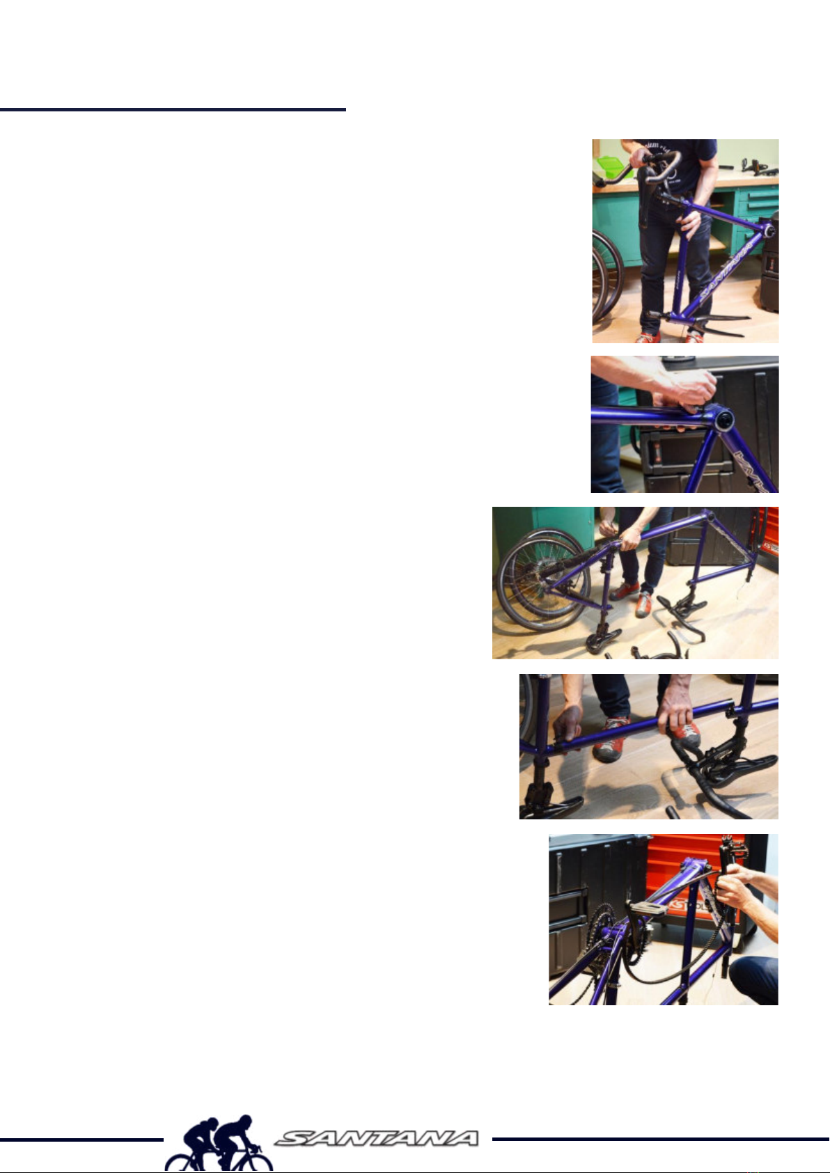
9. The tandem is now placed on the wheels so that the captain handlebar can
be placed on the steerer tube.
a) First remove the top cap from the steerer tube before attaching the stem
and handlebars.
b) Then replace the top cap of the headset and tighten until the fork has no
more play (only approx. 1-2 Nm - do not tighten completely!). Adjusting
the headset play is not necessary if a locking collar on the steerer tube
ensures that the fork remains fixed when the handlebars are removed.
c) Now align the handlebars with the front wheel and tighten the 4 mm Allen screws on the side of the stem on the
steerer tube.
d) Align the drop bars (racing handlebars) roughly parallel to the ground / top tube and tighten the stem bolts to
approx. 6-7 Nm.
10. Now attach the cables.
a) Starting with the shift cable of the front derailleur, cross the front of the head tube,
on the right side (in the direction of travel) in the right-hand barrel adjusters on
the down tube.
b) The cable for the rear derailleur is also crosses the head tube to the left side and
inserted or screwed to the barrel adjusters. The middle barrel adjusters is provided
for the brake cable to the disc brake.
c) If the tandem is equipped with an electric shifting, there is no need to attach the shifting cables. Instead, only
one cable for the front and the rear derailleurs needs to be plugged at the down tube and at the captain and
stoker bottom brackets.
d) The brake cable for the rear brake is also routed in front of the head tube to the left side and inserted or screwed
into the left barrel adjusters.
11. Now the cables running from the handlebars to the rear can be connected under the bottom tube with the cables
coming from the rear. These cross under the oval bottom tube!
a) Place the rear brake cable under the Captain bottom bracket through the left cable guide and screw it together
by hand with the left brake cable coming from the rear.
b) The shift cable of the rear derailleur is led from the front through the middle cable guide under the captain bottom
bracket and connected with the shift cable of the rear derailleur coming from the right, rear side. Make sure that
the lowest gear is selected so that the tension of the cable is minimized.
c) Finally, the front derailleur cable is routed under the bottom bracket through the right cable guide and
connected to the front derailleur cable coming from the middle, rear side. Again, make sure that the front
derailleur is located above the smallest chainring to minimize cable tension.
12. Then mount the front brake by reattaching the brake caliper removed from the fork to the
post on the fork. In the case of a V-brake, make sure that the return spring of the brake
caliper is inserted into the same hole as on the other side.
13. Finally, the brake cable is hooked in. If the fork is equipped with a racing bike brake
caliper, the plug located on the brake caliper is passed through the fork steerer tube and
tightened from the rear with the sleeve nut (hexagon socket, approx. 8 Nm). The brake
body is then closed.
14. If the tandem is equipped with extras, such as a rack, lowrider, mudguards or bottle
mounts on the stoker lateral tube, these are then mounted.
15. The tandem is now completely assembled. Before driving off, it is essential to ensure that the brakes and shifting are
working correctly. If necessary, these must be adjusted.
a) If the pressure point of the front brake is too late, the barrel adjuster on the brake cable can be unscrewed slightly
to lengthen the brake cable and increase the tension.
b) If the tandem is equipped with a rim brake at the rear, the adjustment is done in the same way as at the front.
c) The brake pads of the front brake should have the same distance on both sides of the rim. The tension of the
spring for the respective brake caliper side can be readjusted via the 3 mm Allen screw on the side.

6
d) In the case of a disc brake, disassembling and reassembling the tandem should not change anything. However,
if adjustment is required, the brake piston can be moved closer to the brake disc using the 5 mm Allen bolt on
the inside of the brake caliper. Likewise, the barrel adjuster on the brake cable in front of the brake caliper can
be slightly unscrewed. Both adjustments result in an earlier pressure point of the disc brake.
e) The rear shifting is adjusted by turning the barrel adjuster on the underside of the down tube. Unscrewing the
adjuster will pull the chain down on the cassette, while screwing the adjuster will pull the chain up on the cassette.
f) Adjusting the front derailleur is done similarly by turning the barrel adjuster on the underside of the down tube.
g) If the tandem is equipped with an electric shifting system, the shifting is adjusted via the shift indicator on the
handlebars, via the smartphone app, or by connecting it to the computer.
h) Before riding, always check the tight fit of the handlebars and the saddles!
Table of contents
Other Santana Bicycle manuals
Popular Bicycle manuals by other brands

Atomic Zombie
Atomic Zombie StreetFox manual

Specialized
Specialized TURBO S owner's manual

Esperia
Esperia BOURGET E230U user manual

Triad
Triad Trike-Notorious Owner's manual & assembly instructions

ELECTRIC WHEELS
ELECTRIC WHEELS EW-620 Assembly and setup instructions

Scott
Scott SCALE CARBON 2013 owner's manual