Punair TIG 315P AC/DC User manual

OWNER'S MANUAL
TIG 315/400P AC/DC

OWNER’S MANUAL -1- PNR-YF-05Y-A1
CONTENTS
1. Contents····················································································································· 1
2. Safety warning············································································································ 2
3. Machine description ··································································································· 3
4. Technical parameters table··························································································· 4
5. Panel function instruction···························································································· 5
6. Installation instruction································································································· 7
7. Operation instruction··································································································· 8
8. Notes or preventive measures ····················································································· 10
9. Maintenance················································································································11
10. Notes before checking ······························································································ 11
11. Questions to be run into during welding ····································································· 12
12. Troubleshooting and fault finding ·············································································· 13
13. Machine explosion diagram························································································ 14
14. Machine component list······························································································15

OWNER’S MANUAL -2- PNR-YF-05Y-A1
SAFETY WARNING!
In the process of welding or cutting, there will be possibility of injury, so please take
protection measure during operation. For more details please review the Operator Safety
Guide, which complies with the preventive requirements of the manufacturer.
Electric shock——May lead to death !!
Set the earth fitting according to applying standard.
Forbidden to touch the bare electric parts and electrode with uncovered skin, wet gloves or clothes.
Make sure you are insulated from the ground and the workshop.
Make sure you are in safe position.
Gases and fumes——May be harmful to health!
Keep your head out of the gases and fumes.
When arc welding, ventilators or air extractors should be used to avoid breathing gases.
Arc rays——Harmful to your eyes, burn your skin.
Wear suitable protective mask, light filter and protective garment to protect eyes and body.
Prepare suitable protective mask or curtain to protect looker-on.
Fire
Welding spark may cause fire. Make sure there is no tinder stuff around the welding area.
Noise——Excessive noises will be harmful to hearing.
Use ear protector or others means to protect ear.
Warn looker-on that noise is harmful to hearing.
Malfunction——When trouble happens, contact with authorized professionals
If trouble happens during installation and operation, please follow this manual instruction to check up.
If you fail to fully understand the manual, or fail to solve the problem with the instruction, you should
contact the suppliers or the service center for professional help.
WARNING!
Creepage-protecting switch should be added when using the machine!!!

OWNER’S MANUAL -3- PNR-YF-05Y-A1
MACHINE DESCRIPTION
The welding machine is a rectifier adopting the most advanced inverter technology.
The development of inverter gas-shielded welding equipment profits from the development of the inverter
power supply theory and components. Inverter gas-shielded welding power source utilizes high-power
component MOSFET to transfer 50/60Hz frequency up to 100 KHz, then reduce the voltage and commutate,
and output high-power voltage via PWM technology. Because of the great reduce of the main transformer’s
weight and volume; the efficiency increases by 30%. The appearance of inverter welding equipment is
considered to be a revolution for welding industry.
TIG 315/400P AC/DC series machine are the AC/DC and MMA three-way machines, which are developed by
our company newly. Its biggest characteristics is that DC function can be used to weld stainless steel, alloyed
steel, carbon steel, copper and other color metals and AC function can be used to weld aluminum and
aluminum alloy materials, such as welding of scooters, bicycles.
TIG 315/400P AC/DC series machine adopts our company’s exclusive HF inverter technology. Compared
with traditional machine, it is compact in volume, light in weight, effective in transfer, power-saving; com
pared with imported machine, it is low in price, strong in power net adaptability. What’s more, it adopts twice
inverter technology and has characteristics of pure square wave output, good arc force, wide cleaning range
and continuous arc with small current, which guarantee excellent welding result.
Thanks for purchasing our product and hope for your precious advice. We will dedicate to produce the best
products and offer the best service.
WARNING!
The machine is mainly used in industry. It will produce radio wave, so the worker should
make fully preparation for protection.

OWNER’S MANUAL -4- PNR-YF-05Y-A1
TECHNICAL PARAMETERS TABLE
Model
Parameters
TIG 315P AC/DC
TIG315P AC/DC
TIG 400P AC/DC
Power voltage (V)
3ph AC380V±15%
3ph AC415V±15%
3ph AC380V±15%
Frequency (Hz)
50/60
50/60
50/60
Rated input current (A)
15
12.5
20
No-load voltage (V)
70
58.7
70
Output current adjustment (A)
10-315
10-315
10-400
Rated output voltage (V)
22.6
22.6
26
Duty cycle (%)
60
60
60
No-load loss (W)
100
100
100
Arc Ignition
HF
HF
HF
Efficiency (%)
85
85
85
Power factor
0.93
0.93
0.93
Insulation grade
F
F
F
Pulse frequency (low )Hz
0.5-15
0.5-15
0.5-15
Pulse frequency (Middle)Hz
15-450
15-450
15-450
Up slope time (S)
0-10
0-10
0-10
Down slope time (S)
0-10
0-10
0-10
Base current (A)
10-315
10-315
10-400
Start current (A)
10-315
10-315
10-400
Crater current (A)
10-315
10-315
10-400
Post flow time (S)
1-10
1-10
1-10
Duty ratio (%)
40-80
40-80
40-80
Pulse duty ratio (%)
10-90
10-90
10-90
Housing protection grade
IP21
IP21
IP21
Weight (kg)
39
39
39
Dimensions (mm)
616×326×620
616×326×620
616×326×620

OWNER’S MANUAL -5- PNR-YF-05Y-A1
PANEL FUNCTION INSTRUCTION
TIG 315P AC/DC FRONT PANEL INSTRUCTION:
1
Current meter
13
Over heat indicator
2
Panel/remote control altering switch
14
Over current indicator
3
AC/DC altering switch
15
Start current adjustment
4
TIG/MMA altering switch
16
Current up slope time adjustment
5
Frequency altering switch
17
Duty ratio adjustment
6
2T/4T/Repeat switch
18
Pulse frequency adjustment
7
Base current adjustment
19
Negative output terminal
8
Crater current adjustment
20
Gas connector
9
Peak current adjustment
21
Torch switch socket
10
Post flow time adjustment
22
Remote control socket
11
Current slope time adjustment
23
Positive output terminal
12
Clean pulse width adjustment

OWNER’S MANUAL -6- PNR-YF-05Y-A1
TIG 400P AC/DC FRONT PANEL INSTRUCTION:

OWNER’S MANUAL -7- PNR-YF-05Y-A1
INSTALLATION INSTRUCTION
1. Make good connection of shielded gas source. Gas supply passage includes cylinder, argon decompressing
flow meter and pipe. Connecting part of pipe should use hoop or other things to fasten, in case lest argon
leaks out and air gets in.
2. Ground the cables with section area no less than 6mm2to the housing. The way is connecting screw at the
back of the power source to ground device or making sure connection of AC outlet have already reliably and
separately connected ground. The above mentioned 2 ways can be used at the same time for ensuring safety.
3. Correctly connect the arc torch or holder according to the sketch. When using MMA welding: Make sure the
cable, holder and fastening plug have been connected with the ground. Put the fastening plug into the
fastening socket at the “-” terminal and fasten it clockwise. When use TIG welding: Put the gas-electricity plug
of the welding gun to the joint at the front panel, and fasten clockwise. Put the air switch on the gun to the
relevant joint at the front panel, and fasten the screw.
4. Put the fasten plug of the cable to fasten socket of “+” terminal at the front panel and fasten it clockwise then
the earth clamp at the other terminal clamps the work piece.
5. According to input voltage grade, connect power cable with power supply box of relevant voltage
grade. Make sure there is no mistake and the voltage of power supply does not exceed
permission range. After the above job,installation is finished and welding is available.
TIG400P AC/DC INSTALLATION:
1
Current meter
12
Current down slope time
adjustment
2
Remote altering switch
13
Clean pulse width adjustment
3
AC/DC altering switch
14
Duty ratio adjustment
4
TIG/MMA altering switch
15
Current up slope time
adjustment
5
Frequency altering switch
16
Pulse frequency adjustment
6
2T/4T altering switch
17
Positive output terminal
7
Start current adjustment
18
Negative output terminal
8
Base current adjustment
19
Gas connector
9
Crater current adjustment
20
Torch switch socket
10
Peak current adjustment
21
Remote control socket
11
Post flow time adjustment

OWNER’S MANUAL -8- PNR-YF-05Y-A1
Warning:
Any connection operations should be done at the condition that the power has been
cut off. The correct sequence is to connect the electrode holder and the earth clamp to the
welder well first, then put the electric plug into the socket .
OPERATION INSTRUCTION
A. DC TIG WELIDNG
1. Turn on power switch; digital current meter is light; fan begins to run.
2. Turn on the argon switch and adjust gas flow to rated standard.( refer to flow table)
3. When put the switch to “DC” position, it is DC tig arc welding which is for stainless steel, iron, copper and
other metals.
4. Put the switch to “OFF” position, current is adjusted by panel knob. Put the switch to “ON” position,
current is adjusted by pedal.
5. According to requirement to choose “Pulse choosing switch”. “Down position” is no pulse. “Upper
position” is low frequency (0.5—15Hz), “middle position” middle frequency (15—450Hz). And adjust the
“Pulse adjustment knob” to suitable pulse frequency.
6. According to requirement to adjust the duty cycle to suitable position. ( When no pulse, value is 1 )
7. According to requirement to adjust arc initiation current and attenuation time.
8. According to the plate thickness, set suitable welding current and basic value current (When pulse switch is at

OWNER’S MANUAL -9- PNR-YF-05Y-A1
down position, no basic value current).
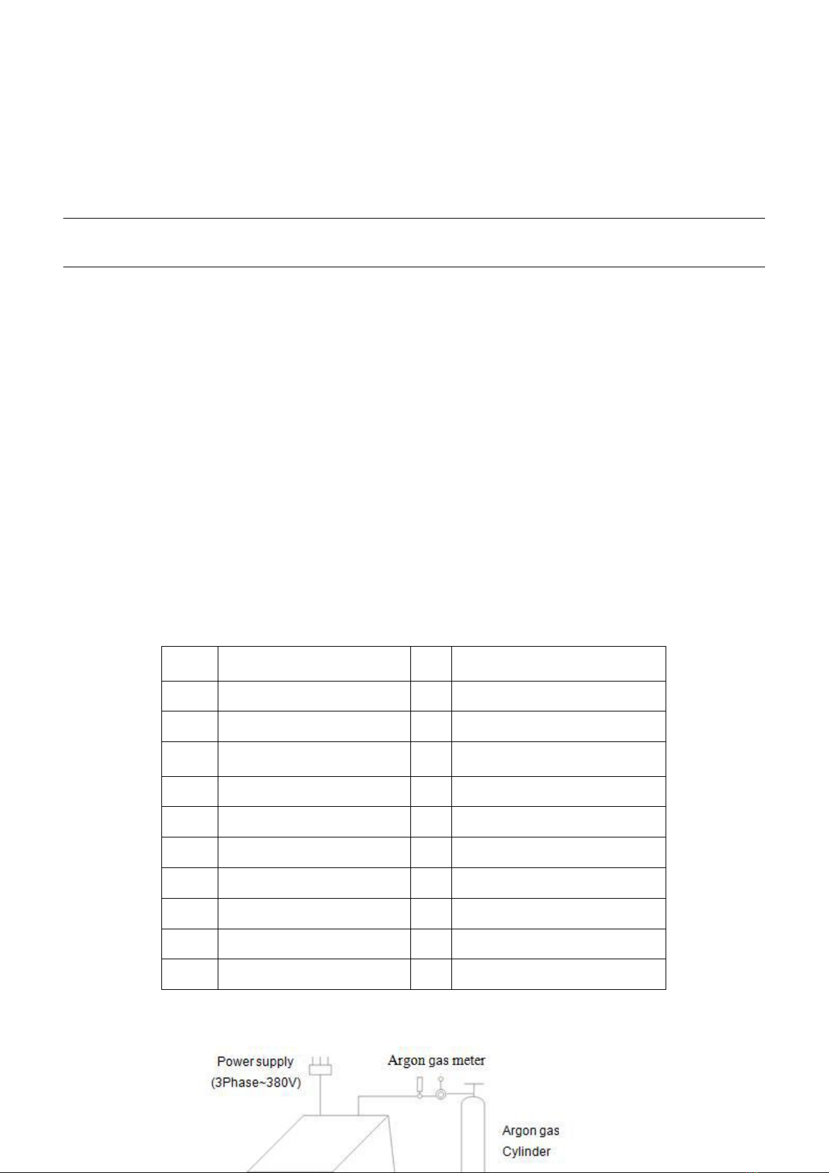
9. Press torch switch and electromagnetic valve starts, you will hear the sound of electricity-releasing HF sparkle
and at the same time, argon comes out from the torch.
10. Keep 2-4mm space between tungsten pole and working plate, and press torch control switch, then between
electrode and work piece HF electricity is released; After arc initiation, HF sparkle disappears soon and
can start to work.
11. When welding finished, adjust the post-flow knob to suitable place in order to protect welding surface.
12. When TIG welding, choose the 2T/4T switch for long welding and spot welding; when 2T, arc initiation and
down slope adjusting function do not work, only welding current works.
13. When 4T, pressing the torch switch is arc initiation current, while releasing the switch is welding current;
pressing again is down slope time adjusting, releasing again off working.
14. When repeat, arc initiation and down slope current are the same, and arc putting out is off working.
B. AC TIG WELDING
1. Operating as the1-4 step above. When put the switch to “AC” position, it is AC arc welding which is for
aluminum materials.
2. Pulse duty knob: During AC arc welding, current transfers between up side and down side continuously.
When current goes from tungsten stick to work piece, it is positive current time. At this moment, stick
heats slightly and quantity of heat is concentrated, which is good for welding. When current goes from
work piece to stick, it is down side current. At this moment, it can clean oxide at the surface of work force,
which improves welding result. But the stick may be burnt out because of over heat; the knob is for
adjusting time ratio of positive and reversed current.
3. Operating as the10-12 step above.
Attached:The Maximum permissible current for different power and tungsten stick
tungsten
stick diameter
(mm)
Direct current (A)
positive current
Negative current
Pure
tungsten
thorium-tungsten
Cerium-tungsten
Pure tungsten
thorium-tungsten
Cerium-tungsten
0.5
2~20
2~20
—
—
1.0
10~75
10~75
—
—
1.6
40~130
60~150
10~20
10~20
2.0
75~180
100~200
15~25
15~25
2.5
130~230
170~250
17~30
17~30
3.2
160~310
225~330
20~35
20~35

OWNER’S MANUAL -10- PNR-YF-05Y-A1
C. MMA welding
1. Turn on power switch; digital current meter is lit; fan begins to wheel.
2. Put the welding switch to “ Down position”, at this time, “Pulse choosing switch”, “2T/4T switch”, “AC/DC switch”
are out of work, only welding current knob can use.
3. Set the welding current according to the work piece thickness.
Attached:Relative value for electrode and current
Electrode(mm)
2.5
3.2
4.0
5.0
Current (A)
70-100
100-140
170-220
230-280
Warning:
It is forbidden to pull out or put in the cable or connector during the process of welding,
which will threat life safety and damage the machine.
NOTES OR PREVENTIVE MEASURES
1. Environment
1)The machine should be operated in dry environments with humidity levels of max 90%.
2)Ambient temperature should be between -10 to 40 degrees centigrade.
3)Avoid welding in sunshine or drippings. Do not let water infilter the machine.
4)Avoid welding in dust area or the environment with corrosive gas.
5)Avoid gas welding in the environment with strong airflow.
2. Safety norms
The welding machine is installed with protection circuit of over voltage, over current and over heat. When
voltage, output current and temperature of machine exceed the required standard, welding machine will
stop working automatically. However, overuse (such as over voltage) will still result in damage to the
welding machine. To avoid this, the user must pay attention to the following:
1)The working area is adequately ventilated!
The welding machine is powerful machine, when it is being operated, it generated by high currents,
and natural wind will not satisfy machine cool demands. So there is a fan inside the machine to cool
down machine. Make sure the intake is not in block or covered. The distance between the welding
machine and other objects surrounded should be at least 0.3 meter. User should make sure the
working area is adequately ventilated. It is important for the performance and the life span of the
machine.

OWNER’S MANUAL -11- PNR-YF-05Y-A1
2)Do not over load!
The operator should remember to watch the max duty current (Response to the selected duty cycle).
Keep welding current is not exceed max duty cycle current. Over-load current will damage and burn
up machine.
3)No over voltage!
Power voltage can be found in diagram of main technical data. Automatic compensation circuit of
voltage will assure that welding current keeping in allowable range. If power voltage exceeds
allowable range limit, it will damage the components of machine. The operator should understand
this situation and take preventive measures.
4)There is a grounding screw at the back of the welding machine, with a grounding marker on it.
Before operation, welding crust must be grounded reliable with cable which section is over 6 square
millimeter, in order to prevent from static electricity and accidents because of electricity leaking.
5)If welding time is exceeded duty cycle limited, welding machine will stop working for protection.
Because machine is overheated, temperature control switch is on “ON’’ position and the indicator
light is yellow. In this situation, you don’t have to pull the plug to let the fan cool the machine. When
the indicator light is off, and the temperature goes down to the standard range, it can weld again.
MAINTENANCE
WARNING:
All the maintenance and repairing work must be done at the condition that the power is
off. Please confirm the power plug is pull out of the socket before opening the machine
shell.
1. Remove dust by dry and clean compressed air regularly. If the welding machine is operated in heavy
smoke or badly polluted air, the machine needs to be cleaned every month.
2. Pressure of compressed air must be at a reasonable level in order to prevent damage to small
components of the machine.
3. Check internal circuit of welding machine regularly and make sure the cable circuit is connected correctly
and connectors are connected tightly (especially insert connector and components). If there is any rusty
or loosing parts, please do the polishing work immediately, and connect them tightly.
4. Avoiding water and steam enter into the machine. If this happened, please dry the machine then check
the insulation of the machine.
5. If the welding machine is not operated for a long time, please keep it into packing box and stored in dry
environment.
NOTES BEFORE CHECKING

OWNER’S MANUAL -12- PNR-YF-05Y-A1
WARNING
Blind experiment and careless repair may lead to more problems and make formal check and repair
more difficult. When the machine is electrified, the bared parts are with life-threatening voltage. Any
direct and indirect touch will cause electric shock, and severe electric shock will lead to death.
Warning
Connecting the welder directly with the electric generator will damage the maintenance due to the
over-voltage pulse. Only the asynchronous electric generator with stable frequency and voltage is allowed to
connect with the welding machine. Any damage that is caused by directly connecting with the electric
generator is out of the free maintenance guarantee.
NOTICE: In the period of guarantee maintenance, if user makes wrong check and repair for
malfunction of welding/cutting machines without our permission, the free maintenance guarantee
offered will be invalid
QUESTIONS TO BE RUN INTO DURING WELDING
Any of the following conditions may be related to the parts, gas, environment factor, supply powers. Please try
to improve the environment to avoid them.
A. Black welding spot
This condition indicates poorly protected welding spot from oxidizing. User may check as following:
1. Make sure the valve of argon cylinder is turned on and its pressure is enough. Argon cylinder must be
filled up to enough pressure again if pressure of cylinder is below 0.5Mpa.
2. Check if the flow meter is turned on and has enough flow. User can choose different flow according to
welding current in order to save gas .But too small flow may cause black welding spot because preventive
gas is too short to cover welding spot .We suggest that flow of argon must be kept min 3L/min.
3. Check if torch is in block.
4. If gas passage is not airtight or gas is not pure will lower welding quality.
5. Strong air flow is in the welding environment will also lower welding quality.
B. Arc-striking is difficult and easy to pause
1. Make sure quality of tungsten electrode is high.
2. Grind end of the tungsten electrode to taper .If tungsten electrode is not grinded ,that will be
difficult to strike arc and cause unstable arc .

OWNER’S MANUAL -13- PNR-YF-05Y-A1
C. Output current not to rated value:
When power voltage departs from the rated value, it will make the output current not matched with rated value;
When voltage is lower than rated value, the max output may lower than rated value.
D. Current is not stable when machine is being operated:
It has something with factors as following:
1. The power net voltage has been changed.
2. There is harmful interference from power net or other equipment.
E. Serious splashing in MMA welding:
May be the welding current is too big, while the electrode diameter is too small;
The output terminal polarity is reversed, should use an anti- polarity under ordinary weld process, namely the
Electrode that should connect to the “+” terminal, but the work piece should connect to the “-” terminal, please
transpose the polarity.
TROUBLESHOOTING AND FAULT FINDING
TIG 315/400PAC/DC fault symptom and solutions.
Faults symptom
Solutions
Power indicator is not lit, fan
does not work and no welding
output
1. Power switch is damaged.
2. Make sure the electric wire net connecting to input cable is working alright
3. Make sure if input cable has broken circuit.
Power indicator is lit, fan is
working, The button on the
welding torch has no effect
1. Check if components are poor connects.
2. Check if connector of output terminal is break circuit and poor connect.
3. The control board is damaged. (Contact with dealer or manufacturer).

OWNER’S MANUAL -14- PNR-YF-05Y-A1
Abnormal indicator is lit, power
indicator is lit, fan is working
1. The high voltage transformer has been hit through or not.
2. The MOSFET is damaged.
3. The Fast Rectifying Diode is damaged.
4. The control board has a fault.
5. The feedback circuits is in fault. (Contact with dealer or manufacturer).
fan is working, power indicator
is lit, electromagnetic valve is
actuate, no HF arc-striking
sound, abnormal indicator is not
lit
1. The arc ignition part has a fault.
2. The jet of discharge electricity is too far away or have adhesive
appearance.
3. The high voltage transformer is damaged.
4. The arc relay is damaged.
5. The control board has a fault.
Air switch cannot close.
1. The Air switch has problem.
2. The three-phase Rectifier is damaged, replace it.
3. Check the machine for short-circuit .
If the machine fails to work normally after maintenance and check, please contact with the local distributor or
OUR after-sale service center.
WELDING EXPLOSION DIAGRAM
TIG400PAC/DC:

OWNER’S MANUAL -15- PNR-YF-05Y-A1
MACHINE COMPONENT LIST
TIG400PAC/DC:

OWNER’S MANUAL -16- PNR-YF-05Y-A1
NO.
序号
NAME
Quantity/set
1
Carbon film resistor
1
2
Enamel cover resistor
4
3
Polyester capacitance
1
4
Frequency transformer
1
5
Frequency transformer
1
6
Reactance implement
1
7
Three-phase diode bridge
1
8
Light emitting diode
2
9
Thermo-sensitive switch
2
10
Electrical shunt
1
11
Ship form switch
3
12
Gas switch
1
13
Last front-panel
1
14
Descend front-panel
1
15
Left side panel
1
16
Right side panel
1
17
Bottom
1
18
Top panel
1
19
Partition board
1
20
Vertical beam
4
21
Vertical beam
2
22
Vertical beam
2
23
Cross beam
2
24
Handle rocker
2
25
Top insulate board
1
26
Top panel insulate board
1
27
Middle insulate board
1
28
Bottom insulate board
1
29
Bottom panel insulate board
1
30
Control insulate board
1
31
Control insulate board
1
32
insulate board
8
33
AC driver panel insulate board
1
34
HF panel insulate board
1
35
Absorber panel insulate board
1
36
Three phase panel insulate board
1
37
Handle switch panel insulate board
1
38
Shield board
1
39
Potentiometer shim
10
40
Fan cover
2
41
Fan cover
2
42
Connector film
2
43
Copper connector
1
44
Copper connector
1
45
Gas/Electric integrate joint
1

OWNER’S MANUAL -17- PNR-YF-05Y-A1
46
Angled switch
1
47
Control panel brace board
1
48
Triangle brace board(left)
1
49
Triangle brace board(right)
1
50
Reactance implement support
1
51
Radiator
1
52
Radiator
1
53
Radiator
1
54
Radiator
1
55
Radiator
1
56
Heat transfer board
1
57
Digital meter
1
58
Fan
2
59
Fan net
2
60
Solenoid valve
1
61
2"artificial rubber fix tyre
2
62
2"artificial rubber direct tyre
2
63
Self-locking fastening
1
64
Knob
10
65
Handle holder
4
66
Torch switch socket
1
67
Torch switch socket
1
68
Quick socket
2
69
1st inverter middle board
1
70
Arc ignition board
1
71
Handle switch board
1
72
Three phase panel
1
73
Absorber panel
1
74
Control panel
1
75
AC driver panel
1
76
AC/DC control panel
1
77
Potentiometer control panel
1
78
1st inverter top board
1
79
2nd inverter board
1
80
2nd inverter board
1
81
Bottom board
1
82
TIG400AC/DC arc ignition device
1
83
Ship form switch
2
This manual suits for next models
1
Table of contents
Other Punair Welding System manuals
Popular Welding System manuals by other brands

Miller
Miller Millermatic Pulser M-15 Gun owner's manual

Sartorius
Sartorius Biowelder TC quick start guide

GCE
GCE U7 Instructions for use

Miller
Miller LMSW-52 owner's manual

Hobart Welding Products
Hobart Welding Products AirForce 625 owner's manual

Campbell Hausfeld
Campbell Hausfeld WS0900 Operating instructions and parts manual