EWM TGM 40230 Handy User manual

Operating instructions
EN
Electrode grinding machine
TGM 40230 Handy
099-003412-EW501
Observe additional system documents!
09.08.2023

General instructions
WARNING
Read the operating instructions!
The operating instructions provide an introduction to the safe use of the products.
• Read and observe the operating instructions for all system components, especially the sa-
fety instructions and warning notices!
• Observe the accident prevention regulations and any regional regulations!
• The operating instructions must be kept at the location where the machine is operated.
• Safety and warning labels on the machine indicate any possible risks.
Keep these labels clean and legible at all times.
• The machine has been constructed to state-of-the-art standards in line with any applicable
regulations and industrial standards. Only trained personnel may operate, service and re-
pair the machine.
• Technical changes due to further development in machine technology may lead to a dif-
fering welding behaviour.
In the event of queries on installation, commissioning, operation or special conditions at the
installation site, or on usage, please contact your sales partner or our customer service
department on +49 2680 181-0.
A list of authorised sales partners can be found at www.ewm-group.com/en/specialist-dealers.
Liability relating to the operation of this equipment is restricted solely to the function of the equipment. No
other form of liability, regardless of type, shall be accepted. This exclusion of liability shall be deemed ac-
cepted by the user on commissioning the equipment.
The manufacturer is unable to monitor whether or not these instructions or the conditions and methods
are observed during installation, operation, usage and maintenance of the equipment.
An incorrectly performed installation can result in material damage and injure persons as a result. For this
reason, we do not accept any responsibility or liability for losses, damages or costs arising from incorrect
installation, improper operation or incorrect usage and maintenance or any actions connected to this in
any way.
© EWM GmbH
Dr. Günter-Henle-Strasse 8
56271 Mündersbach Germany
Tel.: +49 2680 181-0, Fax: -244
Email: info@ewm-group.com
www.ewm-group.com
The copyright to this document remains the property of the manufacturer.
Copying, including extracts, only permitted with written approval.
The content of this document has been prepared and reviewed with all reasonable care. The information
provided is subject to change; errors excepted.
Data security
The user is responsible for backing up data of all changes from the factory setting. The user is liable for
erased personal settings. The manufacturer does not assume any liability for this.

Contents
Notes on using these operating instructions
099-003412-EW501
09.08.2023
3
1 Contents
1Contents .......................................................................................................................................... 3
2For your safety ............................................................................................................................... 4
2.1 Notes on using these operating instructions .......................................................................... 4
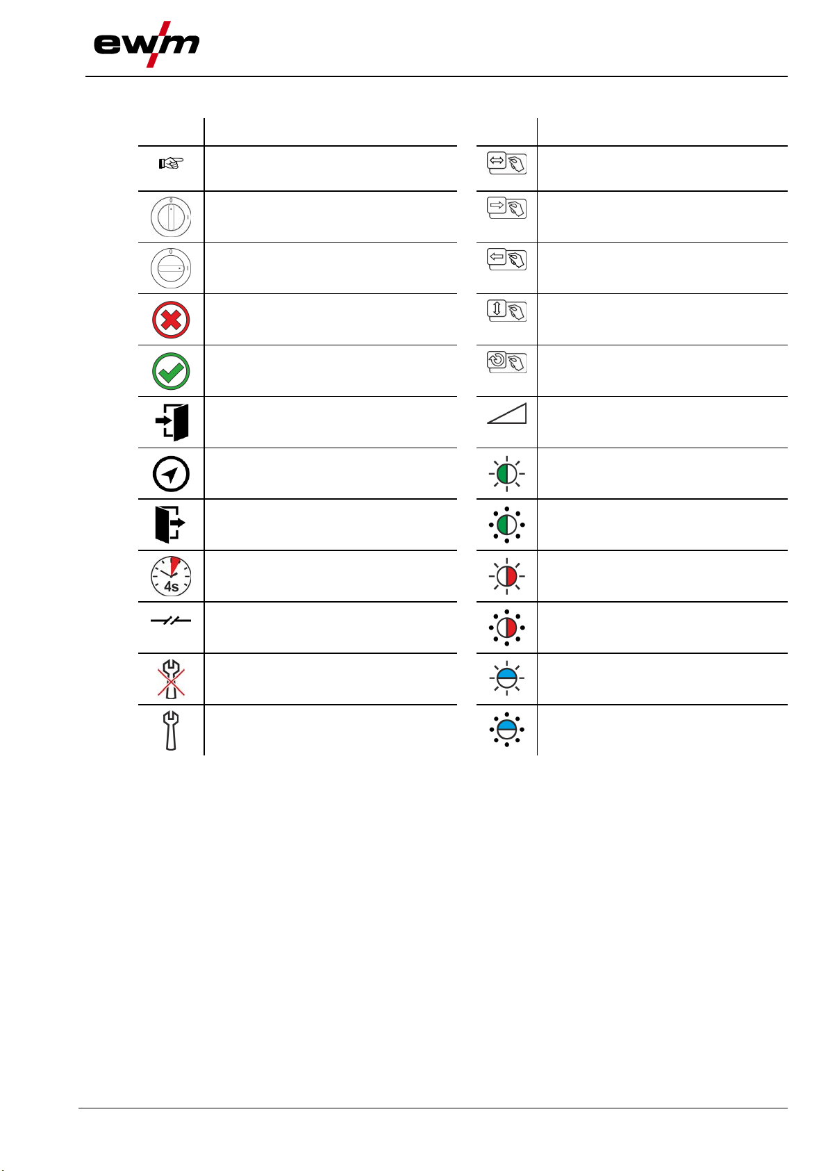
2.2 Explanation of icons ............................................................................................................... 5
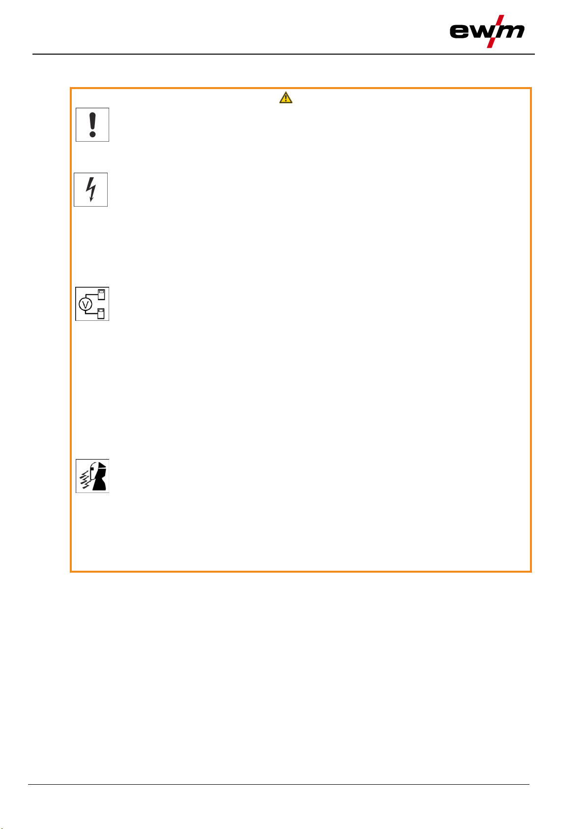
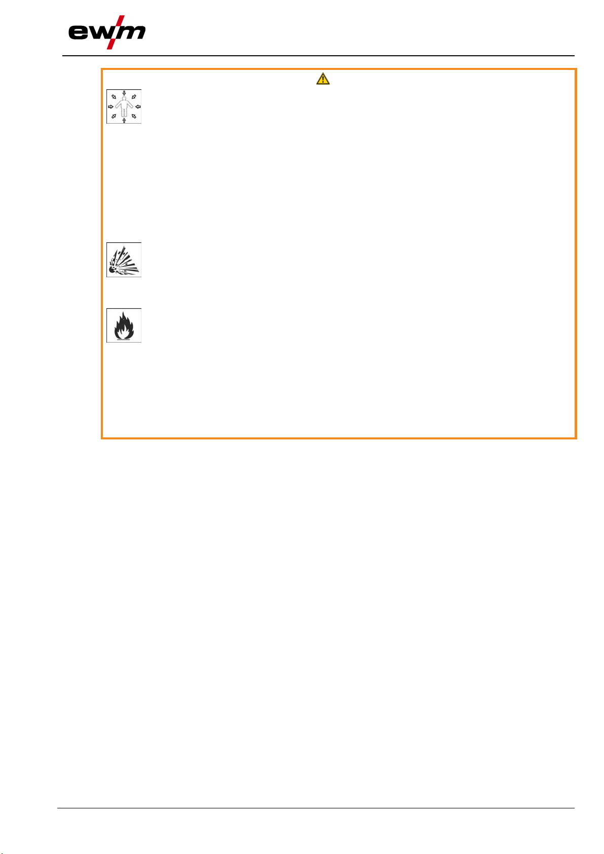
2.3 Safety instructions .................................................................................................................. 6
2.4 Transport and installation ...................................................................................................... 9
3Intended use ................................................................................................................................. 11
3.1 Applications .......................................................................................................................... 11
3.2 Documents which also apply ............................................................................................... 11
3.2.1 Warranty ............................................................................................................... 11
3.2.2 Declaration of Conformity ..................................................................................... 11
3.2.3 Service documents (spare parts) ......................................................................... 11
4Machine description – quick overview ...................................................................................... 12
4.1 TGM 40230 Handy ............................................................................................................... 12
5Design and function ..................................................................................................................... 13
5.1 Transport and installation .................................................................................................... 13
5.1.1 Ambient conditions ............................................................................................... 14
5.1.2 Mains connection .................................................................................................. 15
5.1.2.1 Mains configuration ............................................................................... 15
5.2 Presets ................................................................................................................................. 15
5.2.1 Selecting the grinding track .................................................................................. 15
5.2.2 Preparing electrodes for the grinding process ..................................................... 16
5.2.3 Setting the grinding angle of the tungsten electrode ............................................ 17
5.2.4 Setting the speed .................................................................................................. 18
5.2.5 Guideline values for speed controller setting ....................................................... 18
5.3 Inserting the electrode ......................................................................................................... 19
5.4 Grinding the electrode.......................................................................................................... 19
5.5 Changing the filter ................................................................................................................ 20
5.6 Replacing the grinding disk .................................................................................................. 22
6Maintenance, care and disposal ................................................................................................. 24
6.1 Cleaning ............................................................................................................................... 24
6.2 Disposing of equipment ....................................................................................................... 25
7Technical data .............................................................................................................................. 26
7.1 TGM 40230 Handy ............................................................................................................... 26
8Replaceable parts ........................................................................................................................ 27
8.1 TGM 40230 Handy ............................................................................................................... 27
9Appendix ....................................................................................................................................... 28
9.1 Searching for a dealer.......................................................................................................... 28

For your safety
Notes on using these operating instructions
4
099-003412-EW501
09.08.2023
2 For your safety
2.1 Notes on using these operating instructions
DANGER
Working or operating procedures which must be closely observed to prevent imminent
serious and even fatal injuries.
• Safety notes include the "DANGER" keyword in the heading with a general warning symbol.
• The hazard is also highlighted using a symbol on the edge of the page.
WARNING
Working or operating procedures which must be closely observed to prevent serious
and even fatal injuries.
• Safety notes include the "WARNING" keyword in the heading with a general warning sym-
bol.
• The hazard is also highlighted using a symbol in the page margin.
CAUTION
Working or operating procedures which must be closely observed to prevent possible
minor personal injury.
• The safety information includes the "CAUTION" keyword in its heading with a general warn-
ing symbol.
• The risk is explained using a symbol on the edge of the page.
Technical aspects which the user must observe to avoid material or equipment damage.
Instructions and lists detailing step-by-step actions for given situations can be recognised via bullet
points, e.g.:
• Insert the welding current lead socket into the relevant socket and lock.

For your safety
Explanation of icons
099-003412-EW501
09.08.2023
5
2.2 Explanation of icons
Symbol
Description
Symbol
Description
Indicates technical aspects which the
user must observe.
Activate and release / Tap / Tip
Switch off machine
Release
Switch on machine
Press and hold
Incorrect / Invalid
Switch
Correct / Valid
Turn
Input
Numerical value – adjustable
Navigation
Signal light lights up in green
Output
Signal light flashes green
Time representation (e.g.: wait 4 s / ac-
tuate)
Signal light lights up in red
Interruption in the menu display (other
setting options possible)
Signal light flashes red
Tool not required/do not use
Signal light lights up in blue
Tool required/use
Signal light flashes blue

For your safety
Safety instructions
6
099-003412-EW501
09.08.2023
2.3 Safety instructions
WARNING
Risk of accidents due to non-compliance with the safety instructions!
Non-compliance with the safety instructions can be fatal!
• Carefully read the safety instructions in this manual!
• Observe the accident prevention regulations and any regional regulations!
• Inform persons in the working area that they must comply with the regulations!
Risk of injury from electrical voltage!
Voltages can cause potentially fatal electric shocks and burns on contact. Even low vol-
tages can cause a shock and lead to accidents.
• Never touch live components such as welding current sockets or stick, tungsten or wire
electrodes!
• Always place torches and electrode holders on an insulated surface!
• Wear the full personal protective equipment (depending on the application)!
• The machine may only be opened by qualified personnel!
• The device must not be used to defrost pipes!
Hazard when interconnecting multiple power sources!
If a number of power sources are to be connected in parallel or in series, only a techni-
cal specialist may interconnect the sources as per standard IEC 60974-9:2010: Installa-
tion and use and German Accident Prevention Regulation BVG D1 (formerly VBG 15) or
country-specific regulations.
Before commencing arc welding, a test must verify that the equipment cannot exceed
the maximum permitted open circuit voltage.
• Only qualified personnel may connect the machine.
• When taking individual power sources out of operation, all mains and welding current leads
must be safely disconnected from the welding system as a whole. (Hazard due to reverse
polarity voltage!)
• Do not interconnect welding machines with pole reversing switch (PWS series) or machines
for AC welding since a minor error in operation can cause the welding voltages to be com-
bined, which is not permitted.
Risk of injury due to radiation or heat!
Arc radiation can lead to skin and eye injuries.
Contact with hot workpieces and sparks can lead to burns.
• Use hand shield or welding helmet with the appropriate safety level (depends on the appli-
cation).
• Wear dry protective clothing (e.g. hand shield, gloves, etc.) in accordance with
the applicable regulations of your country.
• Persons who are not directly involved should be protected with a welding curtain or suitable
safety screen against radiation and the risk of blinding!

For your safety
Safety instructions
099-003412-EW501
09.08.2023
7
WARNING
Risk of injury due to improper clothing!
During arc welding, radiation, heat and voltage are sources of risk that cannot be
avoided. The user has to be equipped with the complete personal protective equipment
at all times. The protective equipment has to include:
• Respiratory protection against hazardous substances and mixtures (fumes and vapours);
otherwise implement suitable measures such as extraction facilities.
• Welding helmet with proper protection against ionizing radiation (IR and UV radiation) and
heat.
• Dry welding clothing (shoes, gloves and body protection) to protect against warm environ-
ments with conditions comparable to ambient temperatures of 100 °C or higher and arcing
and work on live components.
• Hearing protection against harming noise.
Explosion risk!
Apparently harmless substances in closed containers may generate excessive pressure
when heated.
• Move containers with inflammable or explosive liquids away from the working area!
• Never heat explosive liquids, dusts or gases by welding or cutting!
Fire hazard!
Due to the high temperatures, sparks, glowing parts and hot slag that occur during
welding, there is a risk of flames.
• Be watchful of potential sources of fire in the working area!
• Do not carry any easily inflammable objects, e.g. matches or lighters.
• Ensure suitable fire extinguishers are available in the working area!
• Thoroughly remove any residue of flammable materials from the workpiece prior to starting
to weld.
• Only further process workpieces after they have cooled down. Do not allow them to contact
any flammable materials!

For your safety
Safety instructions
8
099-003412-EW501
09.08.2023
CAUTION
Smoke and gases!
Smoke and gases may lead to shortness of breath and poisoning! The ultraviolet radia-
tion of the arc may also convert solvent vapours (chlorinated hydrocarbon) into poiso-
nous phosgene.
• Ensure sufficient fresh air!
• Keep solvent vapours away from the arc beam field!
• Wear suitable respiratory protection if necessary!
• To prevent the formation of phosgene, residues of chlorinated solvents on workpieces must
first be neutralised using appropriate measures.
Noise exposure!
Noise exceeding 70 dBA can cause permanent hearing damage!
• Wear suitable ear protection!
• Persons located within the working area must wear suitable ear protection!
According to IEC 60974-10, welding machines are divided into two classes of
electromagnetic compatibility (the EMC class can be found in the Technical
data) > see 7 chapter:
Class A machines are not intended for use in residential areas where the power supply comes
from the low-voltage public mains network. When ensuring the electromagnetic compatibility of
class A machines, difficulties can arise in these areas due to interference not only in the supply
lines but also in the form of radiated interference.
Class B machines fulfil the EMC requirements in industrial as well as residential areas, inclu-
ding residential areas connected to the low-voltage public mains network.
Setting up and operating
When operating arc welding systems, in some cases, electro-magnetic interference can occur
although all of the welding machines comply with the emission limits specified in the standard.
The user is responsible for any interference caused by welding.
In order to evaluate any possible problems with electromagnetic compatibility in the
surrounding area, the user must consider the following: (see also EN 60974-10 Appendix A)
• Mains, control, signal and telecommunication lines
• Radios and televisions
• Computers and other control systems
• Safety equipment
• The health of neighbouring persons, especially if they have a pacemaker or wear a hearing
aid
• Calibration and measuring equipment
• The immunity to interference of other equipment in the surrounding area
• The time of day at which the welding work must be carried out
Recommendations for reducing interference emission
• Mains connection, e.g. additional mains filter or shielding with a metal tube
• Maintenance of the arc welding system
• Welding leads should be as short as possible and run closely together along the ground
• Potential equalization
• Earthing of the workpiece. In cases where it is not possible to earth the workpiece directly,
it should be connected by means of suitable capacitors.
• Shielding from other equipment in the surrounding area or the entire welding system
Electromagnetic fields!
The power source can create electrical or electromagnetic fields that may impair the
function of electronic systems such as EDP and CNC devices, telecommunication,
power and signal lines as well as pacemakers and defibrillators.
• Follow the maintenance instructions > see 6 chapter!
• Unwind the welding leads completely!
• Shield radiation-sensitive equipment or facilities appropriately!
• The function of pacemakers may be impaired (seek medical advice if necessary).

For your safety
Transport and installation
099-003412-EW501
09.08.2023
9
CAUTION
Obligations of the operator!
The respective national directives and laws must be complied with when operating the
machine!
• Implementation of national legislation relating to framework directive 89/391/EEC on the int-
roduction of measures to encourage improvements in the safety and health of workers at
work and associated individual guidelines.
• In particular, directive 89/655/EEC concerning the minimum safety and health requirements
for the use of work equipment by workers at work.
• The regulations applicable to occupational safety and accident prevention in the country
concerned.
• Setting up and operating the machine as per IEC 60974.-9.
• Brief the user on safety-conscious work practices on a regular basis.
• Regularly inspect the machine as per IEC 60974.-4.
The manufacturer's warranty becomes void if non-genuine parts are used!
• Only use system components and options (power sources, welding torches, electrode hold-
ers, remote controls, spare parts and replacement parts, etc.) from our range of products!
• Only insert and lock accessory components into the relevant connection socket when the ma-
chine is switched off.
Requirements for connection to the public mains network
High-performance machines can influence the mains quality by taking current from the mains
network. For some types of machines, connection restrictions or requirements relating to the
maximum possible line impedance or the necessary minimum supply capacity at the interface
with the public network (Point of Common Coupling, PCC) can therefore apply. In this respect,
attention is also drawn to the machines' technical data. In this case, it is the responsibility of the
operator, where necessary in consultation with the mains network operator, to ensure that the
machine can be connected.
2.4 Transport and installation
WARNING
Risk of injury due to improper handling of shielding gas cylinders!
Improper handling and insufficient securing of shielding gas cylinders can cause seri-
ous injuries!
• Observe the instructions from the gas manufacturer and any relevant regulations concern-
ing the use of compressed air!
• Do not attach any element to the shielding gas cylinder valve!
• Prevent the shielding gas cylinder from heating up.

For your safety
Transport and installation
10
099-003412-EW501
09.08.2023
CAUTION
Risk of accidents due to supply lines!
During transport, attached supply lines (mains leads, control cables, etc.) can cause
risks, e.g. by causing connected machines to tip over and injure persons!
• Disconnect all supply lines before transport!
Risk of tipping!
There is a risk of the machine tipping over and injuring persons or being damaged itself
during movement and set up. Tilt resistance is guaranteed up to an angle of 10° (ac-
cording to IEC 60974-1).
• Set up and transport the machine on level, solid ground.
• Secure add-on parts using suitable equipment.
Risk of accidents due to incorrectly installed leads!
Incorrectly installed leads (mains, control and welding leads or intermediate hose pack-
ages ) can present a tripping hazard.
• Lay the supply lines flat on the floor (avoid loops).
• Avoid laying the leads on passage ways.
Risk of injury from heated coolant and its connections!
The coolant used and its connection or connection points can heat up significantly
during operation (water-cooled version). When opening the coolant circuit, escaping
coolant may cause scalding.
• Open the coolant circuit only when the power source or cooling unit is switched off!
• Wear proper protective equipment (protective gloves)!
• Seal open connections of the hose leads with suitable plugs.
The units are designed for operation in an upright position!
Operation in non-permissible positions can cause equipment damage.
• Only transport and operate in an upright position!
Accessory components and the power source itself can be damaged by incorrect connection!
• Only insert and lock accessory components into the relevant connection socket when the
machine is switched off.
• Comprehensive descriptions can be found in the operating instructions for the relevant ac-
cessory components.
• Accessory components are detected automatically after the power source is switched on.
Protective dust caps protect the connection sockets and therefore the machine against dirt and
damage.
• The protective dust cap must be fitted if there is no accessory component being operated on
that connection.
• The cap must be replaced if faulty or if lost!

Intended use
Applications
099-003412-EW501
09.08.2023
11
3 Intended use
WARNING
Hazards due to improper usage!
The machine has been constructed to the state of the art and any regulations and stand-
ards applicable for use in industry and trade. It may only be used for the welding proce-
dures indicated at the rating plate. Hazards may arise for persons, animals and material
objects if the equipment is not used correctly. No liability is accepted for any damages
arising from improper usage!
• The equipment must only be used in line with its designated purpose and by trained or
expert personnel!
• Do not improperly modify or convert the equipment!
3.1 Applications
Portable tungsten electrode grinder for use at the welding site.
3.2 Documents which also apply
3.2.1 Warranty
For more information refer to the "Warranty registration" brochure supplied and our information regarding
warranty, maintenance and testing at www.ewm-group.com!
3.2.2 Declaration of Conformity
This product corresponds in its design and construction to the EU directives listed in the decla-
ration. The product comes with a relevant declaration of conformity in the original.
The manufacturer recommends carrying out the safety inspection according to national and in-
ternational standards and guidelines every 12 months (from commissioning).
3.2.3 Service documents (spare parts)
WARNING
No improper repairs and modifications!
To prevent injuries and damage to the machine, only competent personnel (authorised
service personnel) are allowed to repair or modify the machine.
Unauthorised manipulations will invalidate the warranty!
• Instruct competent personnel (authorised service personnel) to repair the machine.
Spare parts can be obtained from the relevant authorised dealer.

Machine description – quick overview
TGM 40230 Handy
12
099-003412-EW501
09.08.2023
4 Machine description – quick overview
4.1 TGM 40230 Handy
Figure 4-1
Item
Symbol
Description 0
1
Infeed channel
2
Guide element for setting the grinding tracks
3
Grinding attachment
4
Depth gauge
5
Grinding attachment clamping bolt
6
On/off switch
7
Speed controller
8
Motor
9
Retaining bolt
10
Ventilation slot for machine cooling
11
Grinding angle scale
12
Filter casing

Design and function
Transport and installation
099-003412-EW501
09.08.2023
13
5 Design and function
WARNING
Harmful electrode material!
Electrodes may contain harmful substances!
• Observe the instructions by the electrode manufacturer!
CAUTION
Open infeed channel!
If the infeed channel is left open, chips and dirt particles can be expelled from the chan-
nel when the grinding disk is running and might get into the eyes or be breathed in!
• Place the electrode holder in the infeed channel before switching on.
• Allow the grinding disk to come to a stop after switching off before removing the electrode
holder from the infeed channel.
Starting with electrode against grinding disc!
If the grinder is started while the electrode lies against the grinding disc, the electrode
can jam and cause damage to the disc, the machine and people!
• When starting the grinder, make sure the electrode does not lie against the grinding disc!
• Before starting the grinder, check the electrode position through the inspection window!
If too much pressure is exerted from the electrode onto the grinding disk, the electrode may
overheat and become annealed. An annealed electrode can become unusable and damage the
machine!
• Do not press the electrode too forcefully against the grinding disk!
• Turn the electrode evenly during the grinding process!
5.1 Transport and installation
CAUTION
Risk of accidents due to supply lines!
During transport, attached supply lines (mains leads, control cables, etc.) can cause
risks, e.g. by causing connected machines to tip over and injure persons!
• Disconnect all supply lines before transport!

Design and function
Transport and installation
14
099-003412-EW501
09.08.2023
5.1.1 Ambient conditions
Equipment damage due to contamination!
Unusually high amounts of dust, acids, corrosive gases or substances can damage the machine
(observe maintenance intervals > see 6 chapter).
• Avoid large amounts of smoke, steam, oily fumes, grinding dust and corrosive ambient air!
Insufficient ventilation results in a reduction in performance and equipment damage.
• Observe the ambient conditions!
• Keep the cooling air inlet and outlet clear!
• Observe the minimum distance of 0.5 m from obstacles!
In operation
Temperature range of the ambient air:
• -25 °C to +40 °C (-13 °F to 104 °F)
Relative humidity:
• up to 50 % at 40 °C (104 °F)
• up to 90 % at 20 °C (68 °F)
Transport and storage
Storage in a closed area; temperature range of the ambient air:
• -40 °C to +70 °C
Relative humidity
• up to 90 % at 20 °C

Design and function
Presets
099-003412-EW501
09.08.2023
15
5.1.2 Mains connection
DANGER
Hazards caused by improper mains connection!
An improper mains connection can cause injuries or damage property!
• The connection (mains plug or cable), the repair or voltage adjustment of the device must
be carried out by a qualified electrician in accordance with the respective local laws or nati-
onal regulations!
• The mains voltage indicated on the rating plate must match the supply voltage.
• Only operate machine using a socket that has correctly fitted protective earth.
• Mains plug, socket and lead must be checked by a qualified electrician on a regular basis!
• When operating the generator, always ensure it is earthed as stipulated in the operating in-
structions. The network created must be suitable for operating machines according to pro-
tection class I.
5.1.2.1 Mains configuration
The machine may only be connected to a one-phase system with two conductors and an earthed
neutral conductor.
Figure 5-1
Legend
Item
Designation
Colour code
L
Outer conductor
brown
N
Neutral conductor
blue
PE
Protective conductor
green-yellow
• Insert mains plug of the switched-off machine into the appropriate socket.
5.2 Presets
5.2.1 Selecting the grinding track
If the result is not satisfactory, the grinding machine provides the option to select different tracks on the
disk, depending on the wear of the diamond disk.
The filter must be replaced whenever the grinding track is changed or if dispersed dust can be
seen constantly in the grinding chamber.

Design and function
Presets
16
099-003412-EW501
09.08.2023
Figure 5-2
Item
Symbol
Description 0
1
Clamping bolt
2
Guide element for setting the grinding tracks
3
"S" mark
4
Grinding disk
5
Grinding track
• Unfasten the clamping bolt.
• Lift up the guide element.
• Rotate the guide element by 90°.
• By turning it, position the angle guide exactly underneath the guide element.
• Insert the guide element into the angle guide.
• Re-tighten the clamping screw.
5.2.2 Preparing electrodes for the grinding process
CAUTION
Incorrect collet chuck!
Using a collet chuck that does not match the electrode size can mean that the electrode
may become loose, the machine damaged and can also result in injury.
• Only use genuine collet chucks!
• Only use collet chucks that match the relevant electrode diameter!
Various collet chucks modified to the electrode diameter should be used to secure the electrodes for the
grinding process.
Status on delivery!
The collet chuck for an electrode with a diameter of 2.4 mm is pre-fitted in the electrode holder at
the factory.
Figure 5-3
Item
Symbol
Description 0
1
Electrode
2
Collet chuck

Design and function
Presets
099-003412-EW501
09.08.2023
17
Item
Symbol
Description 0
3
Electrode holder
Area of application: unalloyed and low-alloy materials
• Select the collet chuck according to the electrode diameter.
• Insert the electrode into the collet chuck.
• Screw the collet chuck into the electrode holder.
Collet chucks supplied!
Collet chucks for electrode diameters of 1.6, 2.4 and 3.2 mm are included as standard. For other
collect chucks, see the > see 8 chapter.
5.2.3 Setting the grinding angle of the tungsten electrode
The grinding angle can be set from 15° to 180° in 5° increments. The angle of 180° creates a right-angled
surface at the electrode tip.
Figure 5-4
Item
Symbol
Description 0
1
Clamping bolt
2
Mark
3
Grinding angle scale
• Unfasten the clamping bolt.
• Move the guide until the mark is pointing to the required degree setting.
• Tighten the clamping bolt.

Design and function
Presets
18
099-003412-EW501
09.08.2023
5.2.4 Setting the speed
Using a speed that matches the electrode diameter is very important to achieve precise and clean grin-
ding of the electrode.
Figure 5-5
Item
Symbol
Description 0
1
Mains connection cable > see 5.1.2 chapter
2
Motor casing
3
Speed controller
• Speed for the individual electrode diameter > see 5.2.5 chapter.
• Set the speed controller to the required value.
5.2.5 Guideline values for speed controller setting
Electrode diameter
mm
0.8 - 1.6
2.0 - 2.4
3.0 - 4.0
Speed controller posi-
tion
No.
1
2
3

Design and function
Inserting the electrode
099-003412-EW501
09.08.2023
19
5.3 Inserting the electrode
Before every grinding operation:
Set the electrode grinding using the grinding attachment clamping bolt depth gauge.
Figure 5-6
Item
Symbol
Description 0
1
Infeed channel
2
Grinding attachment
3
Depth gauge setting bolt
4
Depth gauge
5
Electrode holder
6
Grinding disk
7
Electrode
8
Sight glass for grinding liquid
• Insert the tungsten electrode into the collet chuck and allow to protrude by approx. 35 mm.
• Screw the collet chuck into the electrode holder.
• Insert the electrode holder into the grinding attachment clamping bolt depth gauge.
• Tighten the tungsten electrode by turning the electrode holder to the right.
• Check that the electrode is seated securely.
• Insert the electrode holder slowly into the infeed channel until the tungsten electrode is over the grin-
ding disk. Check the process through the inspection glass.
Depth gauge setting bolt
The setting bolt on the rear of the depth gauge can be used to set the grinding of the tungsten
electrode.
• Rotate out: More grinding
• Rotate in: Less grinding
5.4 Grinding the electrode
A faulty grinding disc can cause damage to the electrode and electrode holder.
• Do not use the grinder if the grinding disc is damaged.
• Use original grinding discs only.

Design and function
Changing the filter
20
099-003412-EW501
09.08.2023
Figure 5-7
Item
Symbol
Description 0
1
Electrode holder
2
Stop piece
3
Infeed channel
4
Grinding attachment
• Check whether the on/off switch is in the “0” position.
• Connect the machine to the power supply.
• Use the sight glass to check that the electrode is not resting on the grinding wheel.
• Switch on the machine.
• Carry out the grinding process with light pressure and slow, even rotation of the electrode holder.
• The grinding process is finished when the stop of the electrode holder is reached.
• Switch off the machine and allow it to come to a standstill.
• Remove the electrode holder from the feed channel.
• Insert the electrode holder into the depth gauge and loosen the electrode by turning it anticlockwise.
5.5 Changing the filter
WARNING
Mains voltage!
Before carrying out any cleaning or testing measures, ensure that all mains connections
and supply lines of the machine are disconnected.
• Disconnect all mains connections and supply lines.
Operation without a filter!
Operating the grinding machine without a filter cartridge may mean that poisonous
dust, chips and smoke are expelled from the machine. Chips, dust and smoke from
welding electrodes can represent a health risk!
• Never operate the machine without a filter cartridge in place!
The filter must be replaced whenever the grinding track is changed or if dispersed dust can be
seen constantly in the grinding chamber.
Other manuals for TGM 40230 Handy
2
Table of contents
Other EWM Grinder manuals