eWON FLB 3202 User manual

support.ewon.biz
eWON Flexy
3G GSM Extension Card
FLB 3 0
This installation guide explains how to install the
eWON Flexy 3G GSM Extension Card FLB 3 0 .
Installation Guide
IG 019 / Rev. 1.4

Table of Contents
1. Product Summary ............................................................................................................. 3
. Safety, Environmental & Regulatory Information ........................................................... 4
.1. Scope ................................................................................................................................................ 4
. . ESD Damage Prevention ............................................................................................................... 4
.3. Applicable Directives, Standards and Compliance ................................................................ 4
.3.1. Applicable European Directives ........................................................................................ 4
.3. . Applicable Safety Standards ............................................................................................. 5
.3.3. FCC Compliance .................................................................................................................. 5
.3.4. Certifications .......................................................................................................................... 5
.4. Official Modem Identification ...................................................................................................... 5
3. Hardware Description ...................................................................................................... 6
3.1. Mechanical Layout and Interfaces .............................................................................. 6
3. . Extension Card Label ...................................................................................................................... 7
3. .1. Label Location and Information Included ...................................................................... 7
3. . . Part Number Structure for Extension Cards .................................................................... 8
3.3. Front Panel LEDs ............................................................................................................................... 8
3.4. Specifications of the 3G GSM Extension Card .......................................................................... 9
3.5. eWON Flexy Extension Cards Environmental Conditions ...................................................... 10
3.6. Plugging the Extension Card into the Base Unit ...................................................................... 10
3.6.1. Base Unit Slot Compatibility .............................................................................................. 10
3.6. . SIM-Card Insertion ............................................................................................................... 11
3.7. Extension Card Insertion ............................................................................................................... 1
3.7.1. Multiple 3G GSM Extension Cards ................................................................................... 13
3.7. . Power Requirements .......................................................................................................... 13
4. Powering On the Base Unit with its Extension Cards .................................................... 14
5. Check Card Detection on the Embedded Web Page ................................................ 15
5.1. Connecting to the Embedded Web Server ............................................................................ 15
5. . Detected Cards Displayed in the System Page ..................................................................... 15
5.3. Modem Information Displayed in the Info Page .................................................................... 16
Revision .............................................................................................................................. 17
Revision History ..................................................................................................................................... 17
Page / 17 eWON Flexy 3G GSM Extension Card FLB 3 0 | IG 019

Chapter 1
Product Summary
1. Product Summary
The present Installation Guide describes the hardware of the 3G GSM Extension Card FLB
3202 of the eWON Flexy family.
The eWON Flexy family is a range of modular industrial gateway/router.
As the name eWON Flexy suggests, it has been designed to enable numerous different
combinations of Extension Cards and Base Units. The present Installation Guide is focusing
on an extension card which, as such, needs to be inserted in one of the Base Units in order
to work. The Base Units have their individual Installation Guide IG-014-0-EN “eWON Flexy -
Base Units”. The present guide addresses shortly how the Extension Cards integrate the Base
Units and we give some recommendations to mount them (see § 4.5 Plugging the Extension
Card into the Base Unit).
Page 3 / 17 eWON Flexy 3G GSM Extension Card FLB 3 0 | IG 019
Chapter
Safety, Environmental & Regulatory Information
. Safety, Environmental & Regulatory Information
.1. Scope
The present heading addresses Safety, Environmental & Regulatory Information for the 3G
GSM Extension Card FLB 3 0 . This Extension Card is basically belonging to the same
compliance frame than the Base Units. In the present case of a telecommunication Extension
Card, additional directives, standards and instructions apply.
. . ESD Damage Prevention
- Important -
Contains parts and assemblies susceptible to damage by electrostatic discharge (ESD). Always
use ESD precautions when handling Extension Cards and the opened Base Unit.
The Extension Card described in the present Installation Guide is a module exposing both
sides of an electronic printed circuit board. Therefore, it is packed in antistatic ESD bags. In
order to avoid ESD damage, the product must be handled with the necessary precaution
including:
•Grounded ESD protective work surface
•Personnel grounding
.3. Applicable Directives, Standards and Compliance
The Extension Card described in the present Installation Guide complies with the R&TTE
directive 1999/5/EC and the FCC regulations related to the wireless modems.
The Extension Card described in the present Installation Guide belongs to class A
Information Technology Equipment (ITE). In a domestic environment this product may cause
radio interference in which case the user may be required to take appropriate measures.
.3.1. Applicable European Directives
The Extension Card described in the present Installation Guide is in conformity with the
following EC directives:
•RoHS Directive 011/65/EU
•EMC Directive 004/108/EC
•R&TTE Directive 1999/5/EC
The product conforms to the corresponding R&TTE articles:
RF spectrum efficiency (Art 3. ); EMC (Art. 3.1b); Safety (Art. 3.11)
Page 4 / 17 eWON Flexy 3G GSM Extension Card FLB 3 0 | IG 019

Chapter
Safety, Environmental & Regulatory Information
.3. . Applicable Safety Standards
The Extension Card described in the present Installation Guide is in conformity with the
following safety standards:
•IEC/EN 60950-1
•UL 60950-1
•CSA-C . No 60950-1-07
.3.3. FCC Compliance
The Extension Card described in the present Installation Guide complies with Part 15, A,
4E and 7 of the FCC Rules. Operating is subject to the following two conditions:
•This device may not cause harmful interference, and
•This device must accept any interference received, including interference that may
cause undesired operation.
.3.4. Certifications
The Extension Card described in the present Installation Guide has been certified by
authorized bodies:
•Certificate Of Compliance (COC) # E350576
•CB certificate # DK- 9479-M1-UL
These certificates can be downloaded as PDF files on the eWON Support web site:
http://support.ewon.biz/flexy
.4. Official Modem Identification
This product contains part identified as follows by national authorities:
•FFC ID: RI7HE910
•IC ID: 5131A-HE910
•GITEKI (MIC) ID: 005-100 69
•JATE ID: AD1 -0318001
Page 5 / 17 eWON Flexy 3G GSM Extension Card FLB 3 0 | IG 019

Chapter 3
Hardware Description
3. Hardware Description
4. Mechanical Layout and Interfaces
SMA-F Female antenna connector
SIM-Card drawer
Backplane connector
Page 6 / 17 eWON Flexy 3G GSM Extension Card FLB 3 0 | IG 019

Chapter 4
Mechanical Layout and Interfaces
4.1. Extension Card Label
4.1.1. Label Location and Information Included
The identification label of the extension cards is placed on the solder side of the PCB.
The different parts of the label are described below:
PN
Part Number:
identifies the type of the card.
Description see 4.1. Part
Number Structure for Extension
Cards
SN
Serial Number
Structure of the Serial Number
1111- 33-0001-44
1111 = MTID (product related)
33 = Year Week
0001 = sequential mfg order
44 = product type
Marks CE, UL,... certificate number and
logos if applicable.
068 Notified Body Number warrantor
of the CE Mark validation
Page 7 / 17 eWON Flexy 3G GSM Extension Card FLB 3 0 | IG 019
Chapter 4
Mechanical Layout and Interfaces
4.1. . Part Number Structure for Extension Cards
FLB3 0 _00/S
FL FL is the prefix for the extensions of the
eWON Flexy family Only FL (constant)
B
1 alphabetic sign (CAP)
Defines the slots of the base module in
which the extension can be inserted.
See also § 4.5.1 Base Unit Slot
Compatibility
A first slots only ●●○○
B last slots only ○○●●
X In any slot ●●●●
3 0 _00 3G GSM Extension Card. The suffix _00 is used for software options.
/S
The suffix might have an optional “/” character
It might also be blank or include “S” character => Indicates compliance with
the UL/IEC/EN 60950 standard.
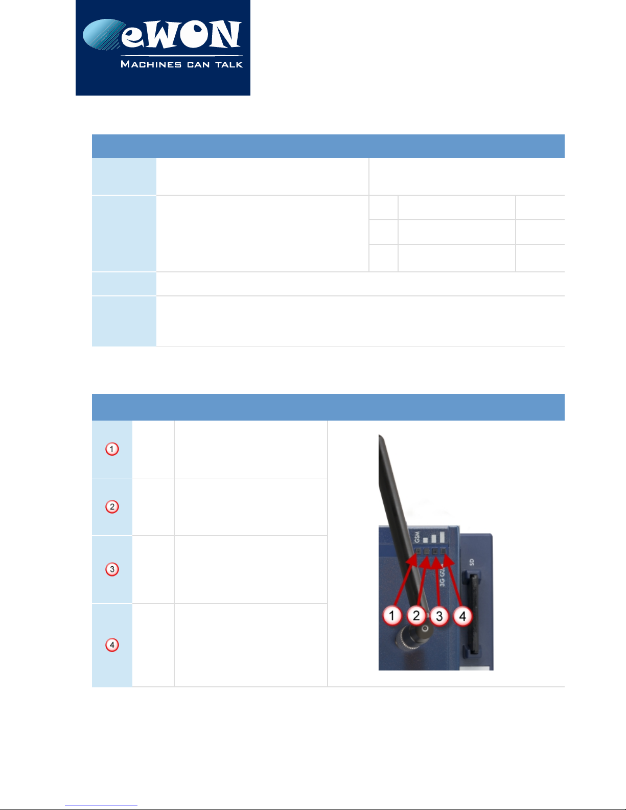
4. . Front Panel LEDs
Item Mark Function Picture
GSM
Tricolor
RED/ORANGE/GREEN
Green ON =
Modem is online
▄
Reception Signal level
Orange ON = level >1
Poor signal
█
Reception Signal level
Orange ON = level >10
Signal is OK
▄
█
Reception Signal level
Orange ON = level >16
Good signal
Page 8 / 17 eWON Flexy 3G GSM Extension Card FLB 3 0 | IG 019

Chapter 4
Mechanical Layout and Interfaces
- Note -
During the modem boot process all 4 LEDs are going ON ORANGE. If they stay ORANGE it means the
modem card as insterted in a rong slot (inducing a Base Unit boot error on its USR LED as ell).
If all signal level LED's are OFF, either:
the modem was not con igured
the modem con iguration is invalid (including wrong PIN-code)
there is no signal at all (level 0)
there is a reception error (level 99).
4.3. Specifications of the 3G GSM Extension Card
Item Value(s)
Protocols and Frequencies GSM/GPRS/EDGE - 850, 900, 1800, 1900 MHz
UMTS/HSUPA - 800/850, 900, AWS1700, 1900, 2100 MHz
Class 5 band GPRS/EDGE Class 33
Antenna Connector Type SMA-F Female
Antenna
(not included in the delivery)
Charact. Value(s)
Range
Depending on frequency band(s) provided by
the network operator, the customer shall use
the most suitable antenna for that/those
band(s).
Impedance 50 Ohms
VSWR
<= 5:1 Absolute max. to avoid permanent
damage
<= :1 Limit to fulfill all regulatory requirements
Input Power > 33 dBm ( W) peak power in GSM
> 4 dBm average power in WCDMA
Tightening
Torque
0.5 Nm. In the absence o a torque wrench, a
so t manual tightening is su icient.
Device conformity has been tested with the reference antenna: Taoglas TG.09.0113
Absolute maximum antenna gain as per FCC's rules and regulations, 47 CFR :
•Part 22H : 5.22dBi
•Part 27 : 3.31dBi
•Part 24E : 6.45dBi
Page 9 / 17 eWON Flexy 3G GSM Extension Card FLB 3 0 | IG 019
Chapter 4
Mechanical Layout and Interfaces
- Important -
This device is intended to be used only in ixed applications. The antenna used or this
transmitter has to be installed to provide a distance o at least 20 cm rom any person and may
not be co-located or operating in conjunction with any other antenna or transmitter.
4.4. eWON Flexy Extension Cards Environmental Conditions
Characteristic Value
Operating temperature - 5 to +70 °C
Storage temperature -40 to +70 °C
Relative humidity 10 to 95% non-condensing
Operating altitude Up to maximum 000m
Storage altitude Up to maximum 3000m
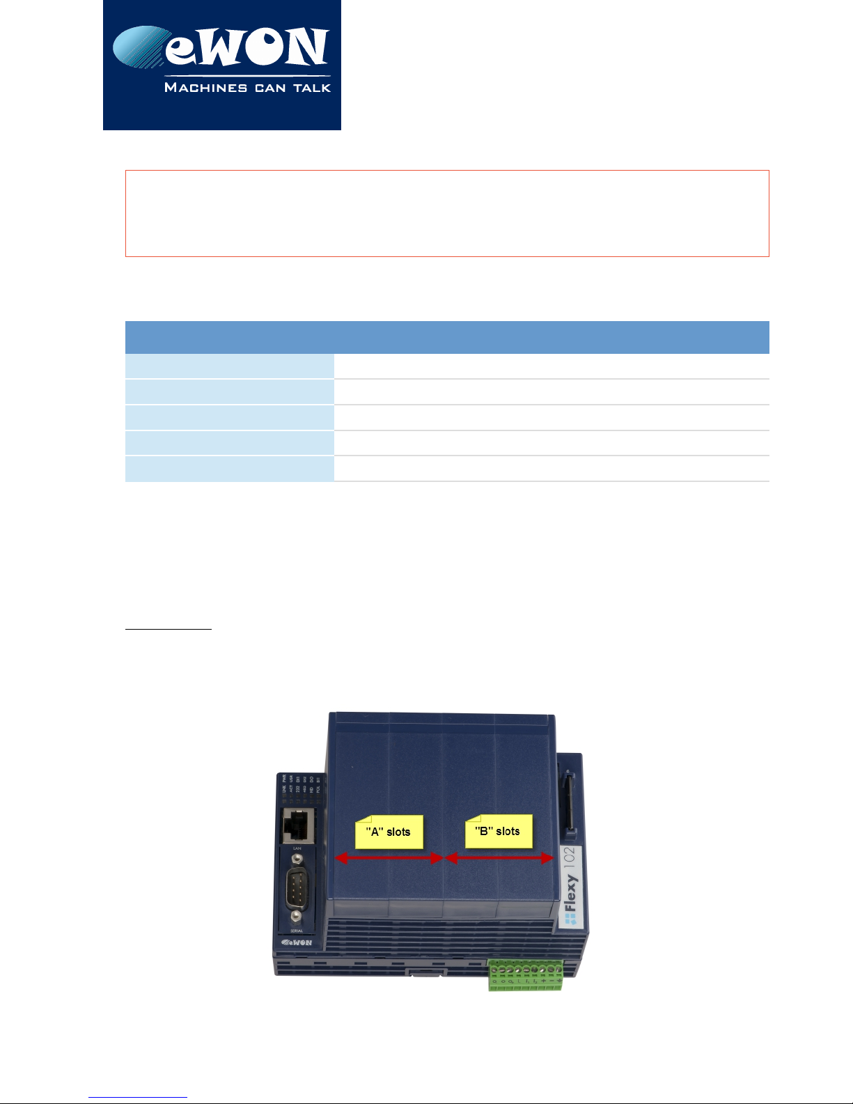
4.5. Plugging the Extension Card into the Base Unit
4.5.1. Base Unit Slot Compatibility
The 3G GSM Extension Card (FLB 3 0 ) must be inserted in one of the “B” slots of the Base
Unit.
Explanation:
The Flexy Base Units feature two type of slots. The A slots are the two first slots starting from
the left. The B slots are the two last slots. Some cards fit in A and B slots. Some not. Cards that
fit only one type of slot have a mechanical mistake-proof security.
Page 10 / 17 eWON Flexy 3G GSM Extension Card FLB 3 0 | IG 019

Chapter 4
Mechanical Layout and Interfaces
The reference code of the Extension Cards includes a letter that defines their compatibility
either with “A” slots, “B” slots or both:
•FLA xxxx - designates cards that fit into “A” slots
•FLB xxxx - designates cards that fit into “B” slots
•FLX xxxx - designates cards that fit into both “A” and “B” slots
In addition to the card reference, each type of extension card bears a visual compatibility
symbol on its front panel. The visual symbols are shown in the table below:
●●○○ first slots only (A)
●●●● In any slot (X)
○○●● last slots only (B)
4.5. . SIM-Card Insertion
A SIM-card obtained from a wireless phone provider is necessary to communicate through
the 3G GSM Extension Card. It should be inserted before inserting the Extension Card in the
Base Unit because there is no external access to the SIM-card holder.
The SIM-card holder is located at the components side of the Extension Card. Carefully slide
the SIM-card in the holder as shown in the picture below. Make sure the card is fully inserted
against its arrest, otherwise it could damage both the drawer and the SIM-card when the
Extension Card will be inserted in the Base Unit. Note the position of the cutoff (1) of the SIM-
card.
Page 11 / 17 eWON Flexy 3G GSM Extension Card FLB 3 0 | IG 019

Chapter 4
Mechanical Layout and Interfaces
4.6. Extension Card Insertion
Please wait 30 seconds after powering off the equipment before inserting (or removing) an
extension card. This is to avoid possible damage to the Base Unit and Extension Card.
Remove the slot filler of the location where you want to insert the new card. To do this, press
on both ends of the cover, note that the hooks are out-centered like shown on the pictures.
Hooks to be pressed are off-centered – press while pulling upwards
This metal tag soldered on the PCB acts as mistake-proof security (mating stop in
housing)
Insert the Extension Card carefully and slide it down until the hooks are clicking. Make sure
the card is completely inserted. DO NOT insist if you feel some resistance when trying to
insert the card. It probably means you are trying to insert the card in a wrong slot. In such
case, check slot compatibility of the relevant Extension Card.
- Note -
Would an extension card be inadvertently orced in a wrong slot, the Base Unit will detect it
and will NOT complete its BOOT process. There ore, the unit will not be accessible through its
LAN inter ace. The slot error is returned by the USR LED. (red ON 1sec, OFF 0.5 sec).
Page 1 / 17 eWON Flexy 3G GSM Extension Card FLB 3 0 | IG 019

Chapter 4
Mechanical Layout and Interfaces
4.6.1. Multiple 3G GSM Extension Cards
The eWON Flexy firmware currently supports up to one 3G GSM Extension Card of type
FLXB3 0 .
The boot process of the Base Unit includes an automated detection of the inserted
Extension Cards. This detection is done sequentially, slot per slot starting from the left to right.
Only the first detected 3G GSM card (the most left one) will be taken into account by the
Flexy firmware. An additional card of the same type will be ignored. Contrary to what
happens when it is inserted in a wrong slot, a 3G GSM card in excess will not alter proper
operation of the Base Unit and other Extension Cards.
4.6. . Power Requirements
The internal power converter of the eWON Flexy Base units has been dimensioned to cover
a broad range of different combinations of Extension Cards. Users should make sure the
total power demand of the Extension Cards does not exceed the capabilities of the Base
Unit. That is why the notion of “Energy Points” has been introduced.
The Installation Guide IG-014-0-EN “eWON Flexy - Base Units” includes a section giving the
Available Energy Points of each type of Base Unit.
The power requirements of each Extension Card is expressed in Energy Demand Points. This
number is meant to check whether the balance with the Available Energy Points of a iven Base
Unit with Extension Cards is OK or not.
3G GSM Extension Card FLB 3202
Energy Demand Points 10
The Installation Guide IG-014-0-EN “eWON Flexy - Base Units” includes examples of practical power
balance calculations.
Page 13 / 17 eWON Flexy 3G GSM Extension Card FLB 3 0 | IG 019
Chapter 5
Powering On the Base Unit with its Extension Cards
5. Powering On the Base Unit with its Extension Cards
When the Base Unit is powered on, it takes approximately 5 seconds for the unit to go
through its self-test procedure. The slots in which the extension cards have been inserted
and their type are detected during this process.
If the boot process completes normally, you should observe the following LED status
•Base Unit USR flashing green slowly
•Extension Card None
- Note -
Would the USR LED o the Base Unit be lashing RED, it might be because the Extension Card
was improperly inserted ( or example in a wrong slot).
Page 14 / 17 eWON Flexy 3G GSM Extension Card FLB 3 0 | IG 019

Chapter 6
Check Card Detection on the Embedded Web
Page
6. Check Card Detection on the Embedded Web Page
The eWON Flexy Extension Card requires no software configuration. It is automatically
detected by the Base Unit when it boots.
6.1. Connecting to the Embedded Web Server
Configure the network parameters of your configuration PC to encompass the IP range of
the eWON LAN.
Connect the PC to one of the LAN port of the eWON Flexy.
Open your Internet browser and access the eWON Flexy internal Web page by entering the
LAN IP address in the URL field (the default address is http://10.0.0.53).
The default
•login is adm
•password is adm
- Important -
For security reasons, changing the default pass ord adm is absolutely required.
To change the adm pass ord, from the menu bar, click on Configuration, Users Setup and double
click on the adm entry to edit its parameters. Enter the ne pass ord t ice and click Save.
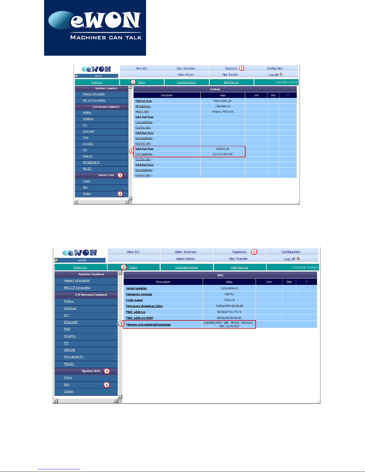
6. . Detected Cards Displayed in the System Page
The System page allows to check the status of the system including detected Extension
Cards. To access the system status summary, click on Diagnostic ( ) > Status (2) > System
Info (3) > System (4). The screen capture below gives an example of an FLB 3 0 extension
card that has been detected in slot 3 (5).
Page 15 / 17 eWON Flexy 3G GSM Extension Card FLB 3 0 | IG 019
Chapter 6
Check Card Detection on the Embedded Web
Page
6.3. Modem Information Displayed in the Info Page
Extended information about the modem - including manufacturer, type and modem
firmware version - is available in the Info page. The path to the Info page is: Diagnostic ( ) >
Status (2) > System Info (3) > Info (4).
Page 16 / 17 eWON Flexy 3G GSM Extension Card FLB 3 0 | IG 019

Revision Information
Revision
Revision History
Revision Level Date Description
1.0 07/05/ 013 Initial version
1.1 9/10/ 013 Official product release version
1. 1 /11/ 014 Changed: chapter 3.3 “Front Panel LED”
Added: chapter .4 “Official Modem
Identification”
1.3 17/11/ 014 Changed: chapter 3. “Extension Card
Label”: 3G Sticker reference adapted, CE
Mark Notified Body Number added
1.4 17/11/ 015 Changed specifications of 3G GSM
extension card
Document build number: 18
Note concerning the warranty and the rights of ownership:
The information contained in this document is subject to modification without notice. Check
http://wiki.ewon.biz for the latest documents releases.
The vendor and the authors of this manual are not liable for the errors it may contain, nor for their
eventual consequences.
No liability or warranty, explicit or implicit, is made concerning the quality, the accuracy and the
correctness of the information contained in this document. In no case the manufacturer's
responsibility could be called for direct, indirect, accidental or other damage occurring from any
defect of the product of errors coming from this document.
The product names are mentioned in this manual for information purposes only. The trade marks and
the product names or marks contained in this document are the property of their respective owners.
This document contains materials protected by the International Copyright Laws. All reproduction
rights are reserved. No part of this handbook can be reproduced, transmitted or copied in any way
without written consent from the manufacturer and/or the authors of this handbook.
eWON sa, Member of ACT'L Group
Page 17 / 17 eWON Flexy 3G GSM Extension Card FLB 3 0 | IG 019
Other manuals for FLB 3202
1
Table of contents
Other eWON Network Card manuals


Popular Network Card manuals by other brands


Monet Broadband
Monet Broadband PC5220 user guide

Allied Telesis
Allied Telesis AT-2872SX Installation and user guide

MGE UPS Systems
MGE UPS Systems minislot 66244 user manual

Maxon
Maxon EPOS4 Hardware reference

Dialogic
Dialogic Media Board VFX/41JCT-LS Quick installation guide

ADC
ADC Wireless Repeaters InterReach Specification sheet